

Page 1
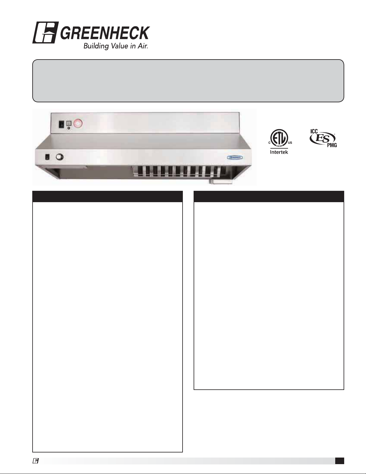
Model GRRS
Fire Ready Hood
®
Installation, Operation and Maintenance Manual
Please read and save these instructions for future reference. Read carefully before attempting to assemble, install,
operate or maintain the product described. Protect yourself and others by observing all safety information. Failure
to comply with instructions could result in personal injury and/or property damage!
REPORT #1293
Listed to UL 300A Standard
WARNING
To reduce the risk of fire, electric shock, or injury
to persons, observe the following:
• Use this unit only in the manner intended by the
manufacturer.
• Before servicing or cleaning unit, switch power off
at service panel and lock the service disconnecting
means to prevent power from being switched on
accidentally. When the service disconnecting means
cannot be locked, securely fasten a prominent
warning device, such as a tag, to the service panel.
• Installation work and electrical wiring must be
done by a qualified person(s) in accordance with all
applicable codes and standards, including fire rated
construction codes and standards.
• Sufficient air is needed for proper combustion
and exhausting of gases through the flue
(chimney) of fuel burning equipment to prevent
backdrafting. Follow the heating equipment
manufacturer’s guideline and safety standards such
as those published by the National Fire Protection
Association (NFPA), and the American Society
of Heating, Refrigeration and Air Conditioning
Engineers (ASHRAE), and the local code authorities.
• When cutting or drilling into wall or ceiling, do not
damage electrical wiring and other hidden utilities.
• To reduce the risk of fire or electric shock, do
not use this range hood with an additional speed
control device.
• Ducted fans must always be vented to the
outdoors.
• To reduce the risk of fire, use only metal ductwork.
• Use with approved wiring only.
• This unit must be grounded.
WARNING
To reduce the risk of range top grease fire:
• Never leave surface units unattended at high
settings. Boilovers cause smoking and greasy
spillovers that may ignite. Heat oils slowly on low or
medium settings.
• Always turn hood ON when cooking at high heat or
when cooking flaming foods.
• Clean ventilation fans frequently. Grease should not
be allowed to accumulate on fan or filter.
• Use proper pan size. Always use cookware
appropriate for the size of the surface element.
To reduce the risk of injury to persons in the event
of a range top grease fire, observe the following:*
• SMOTHER FLAMES with a close-fitting lid, cookie
sheet, or metal tray, then turn off the burner. BE
CAREFUL TO PREVENT BURNS. If the flames do
not go out immediately, EVACUATE AND CALL THE
FIRE DEPARTMENT.
• NEVER PICK UP A FLAMING PAN. You may be
burned.
• DO NOT USE WATER, including wet dishcloths or
towels - violent steam explosion will result.
* Based on “Kitchen Fire Safety Tips” published by
NFPA.
®
Fire Ready Hood
1
Page 2

Table of Contents
Receiving, Unpacking, Handling & Storage ....... 2
Model Number Code ......................... 3
Parts Checklist ............................. 3
Exploded View. . . . . . . . . . . . . . . . . . . . . . . . . . . . . . 3
Sample Installations ......................... 4
Preparing the Install Location
Mounting Bracket .......................... 5
Ductwork ................................ 5
Static Pressure Testing ..................... 5
Fans .................................... 6
Accessories .............................. 6
Installation
Installation Elevation ....................... 7
Mounting Bracket .......................... 7
Installing Hood onto Mounting Bracket ......... 8
Installing the Fan .......................... 9
Range Element Disconnect Installation
Gas Disconnect Valve ..................... 10
Electrical Disconnect Box .................. 10
Installing Accessories
ClockBox ............................... 11
Remote ADA Switches ..................... 11
Manual Pull Station ....................... 11
Ductwork ............................... 11
Electrical Installation
Main Control Power ....................... 12
Electric Disconnect Box .................... 13
Gas Disconnect Valve ..................... 13
Inline/Wall Mount Fan ..................... 14
ClockBox ............................... 14
Remote ADA Switches ..................... 14
Fire Alarm System Connections ............. 14
Wiring Diagram .......................... 15
ClockBox Wiring Diagram .................. 16
Operation ................................. 17
Environmental Monitoring / Pre-Suppression
Functions ............................... 17
Accessing the Internal Components ............ 18
ClockBox Operation and Navigation ........... 19
Test Tank and Demonstration ................. 20
Controller Schematic ........................ 21
Alarm Connections ........................ 21
Self-Monitoring System ...................... 22
After an Actuation ........................ 23
How to Reset the Suppression System ......23-24
Maintaining the System ...................... 25
Inspection Procedures
Nozzle Caps ............................. 25
Fusible Link System ....................... 25
10 Year Maintenance ........................ 25
Lighting .................................. 25
Removing the Extinguisher Tank ............... 26
Service and Recertification Schedule ........... 26
Replacement Parts ......................... 26
Maintenance Log ........................... 27
Our Commitment ........................... 28
Receiving
Upon receiving the product, check to ensure all
items are accounted for by referencing the delivery
receipt or packing list. Inspect each crate or carton
for shipping damage before accepting delivery. Alert
the carrier of any damage detected. The customer will
make notation of damage (or shortage of items) on the
delivery receipt and all copies of the bill of lading which
is countersigned by the delivering carrier. If damaged,
immediately contact your Greenheck Representative.
Any physical damage to the unit after acceptance is not
the responsibility of Greenheck Fan Corporation.
Unpacking
Verify that all required parts and the correct quantity of
each item have been received. If any items are missing,
report shortages to your local representative to arrange
for obtaining missing parts. Confirmation of shipment(s)
must be limited to only items on the bill of lading.
Handling
Handle in such a manner as to keep from scratching or
chipping the coating. Damaged finish may reduce ability
of unit to resist corrosion.
Storage
Units are protected against damage during shipment. If
the unit cannot be installed and operated immediately,
precautions need to be taken to prevent deterioration of
the unit during storage. The user assumes responsibility
of the unit and accessories while in storage. The
manufacturer will not be responsible for damage during
storage. These suggestions are provided solely as a
convenience to the user.
The ideal environment for the storage of units and
accessories is indoors, above grade, in a low humidity
atmosphere which is sealed to prevent the entry of
blowing dust, rain, or snow. Temperatures should be
evenly maintained between 30°F (-1°C) and 110°F
(43°C). All accessories must be stored indoors in a
clean, dry location.
Fire Ready Hood
2
®
Page 3
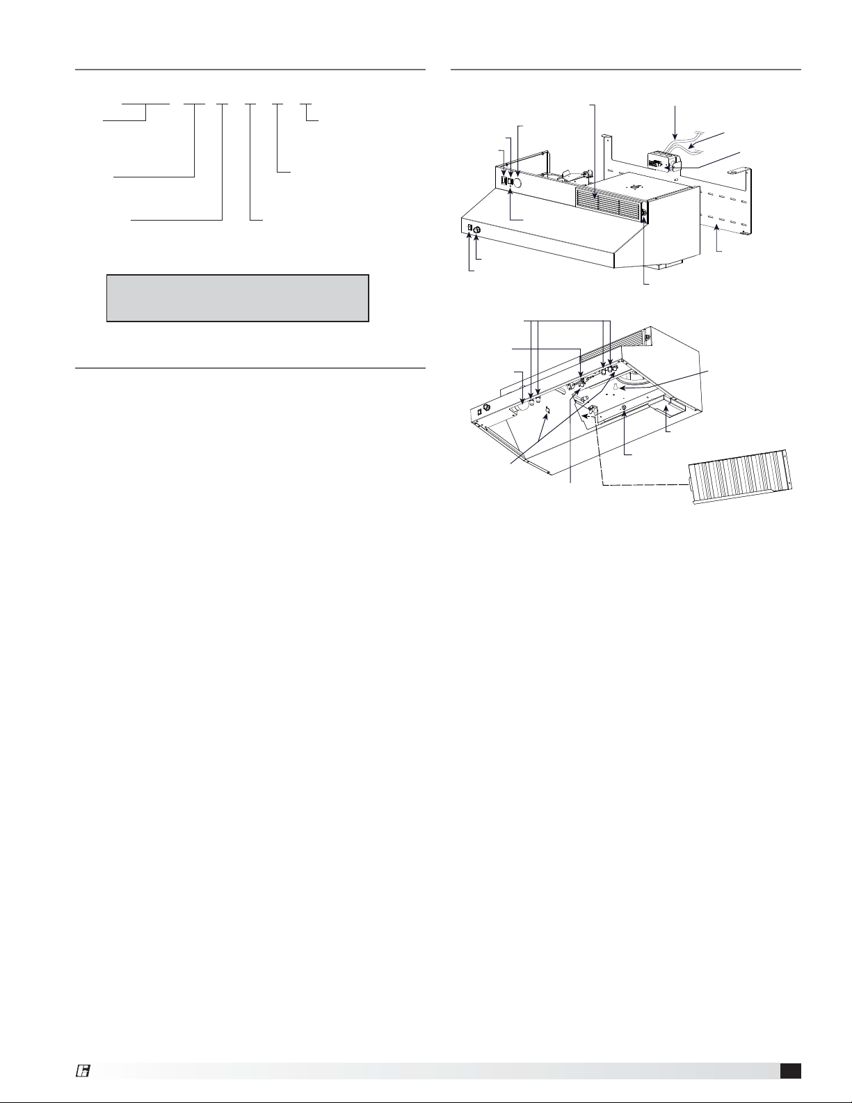
Model Number Code
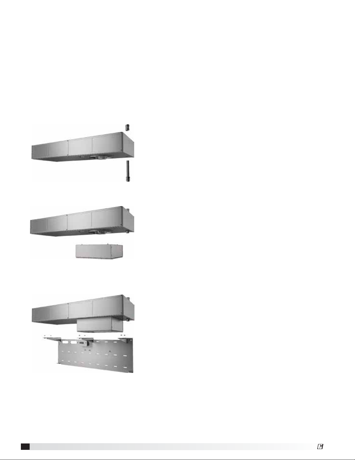
Exploded View
GRRS - 30 - F - E - D - N
Type
Residential
Range
Suppression
Length
30 inches
36 inches
Ventilation
F - Integral Fan - Front Recirculation
R - Integral Fan - Rear Discharge
T - External Fan - Top Discharge
Example: GRRS-30-F-D-N
Greenheck RRS, 30 inches long, with front fan discharge,
with dual element disconnect, NFPA 101 Compliant
Range Disconnect Type
E - Electric
G - Gas
D - Dual (gas and electric)
NFPA 101 Compliance
X - Noncompliant
N - Compliant
External Fan Type
D - Inlet Duct
W - Wall Mount
Parts Checklist
Hood
Back support mounting bracket
External fan (Inline / Wall Mount / None)
• 25 ft. plenum rated wire for plug and play
connection
8 ft. of metal clad wire for hood power connection
(marked with red tape)
Gas disconnect valve (optional)
• 6 ft. shielded control wire for plug and play
connection
Electrical disconnect box (optional)
• 6 ft. shielded control wire for plug and play
connection
8 ft. of metal clad wire for gas disconnect/electrical
disconnect connection (marked with black tape)
Remote switches, ADA (optional)
Manual Pull Kit (optional) consisting of the following:
• Pull Box (1)
• Pull Face (1)
• Elbow Pulley (3)
• 25 ft. Cable and Pin
The ClockBox (optional)
• 20 ft. shielded control wire for plug and play
connection
Reset Switch
Power Switch
Fan Speed Knob
Light Switch
Discharge Nozzles
with protective caps
Fusible Link
Light Bulb
Low Temperature
Switches
Recirculating Vent
(recirculating model)
Extinguisher
Pressure Gauge
LED Status Light
High Temperature
Switch
Electrical Disconnect
(Black Tape)
Thumbscrew to remove vent
on some models
Grease Tray
Thumb Nut (3x)
110 VAC Power Supply
(Red Tape)
Junction Box
Back Support
Mounting Bracket
Thumbscrews (2x)
(inline models)
Grease Filter
®
Fire Ready Hood
3
Page 4
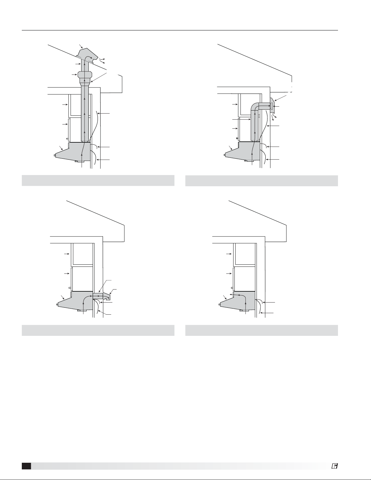
Sample Installations
Roof Cap
(by others)
10 in. Ductwork
Inline Duct Fan
(provided)
Soffit
Cabinet
Range Hood
(provided)
Airflow
7 in. to 10 in. Transition7 in. to 10 in. Transition
Plenum Ready
Supply Cable to Fan
(provided)
110 VAC Supply Cable
(provided)
Power Disconnect Cable
(provided)
Soffit
7 in. Ductwork
Cabinet
Range Hood
(provided)
Airflow
Wall Mount Fan Box
Wall Mount Fan Box
with Access Cover for
with Access Cover for
Service and Mounting
Service and Mounting
(provided)
(provided)
Fan
Plenum Ready
Supply Cable to Fan
(provided)
110 VAC Supply Cable
(provided)
Power Disconnect Cable
(provided)
Soffit
Cabinet
Range Hood
(provided)
External Fan | Inline Fan
External Fan | Wall Mount Fan
Soffit
Cabinet
3½ x 12-in. Ductwork
Airflow
Wall Cap
(by others)
110 VAC Supply Cable
(provided)
Power Disconnect Cable
(provided)
Range Hood
(provided)
Airflow
110 VAC Supply Cable
(provided)
Power Disconnect Cable
(provided)
Integral Fan | Rear Discharge Integral Fan | Front Recirculation
Fire Ready Hood
4
®
Page 5
Preparing the Install Location
Mounting Bracket - The mounting bracket and hood must be centered over the range. If the range is not in place,
the center marking should be relative to it’s final position. Refer to page 7 for bracket mounting points, rear access
holes and access points.
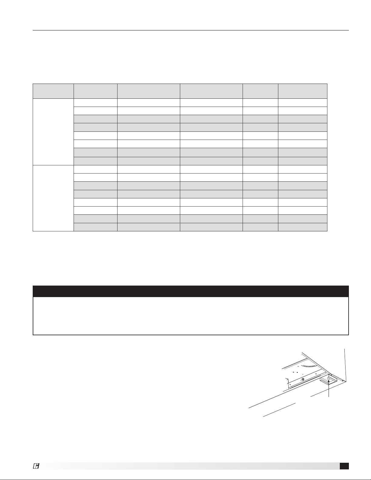
Ductwork - The ductwork and fittings used for outside venting (if applicable) must be carefully selected to ensure
that the static pressure is in line with the fan parameters. The table below displays maximum duct length allowed for
the various fan options.
Hood
Width
30 inches
36 inches
Maximum duct length equals horizontal and vertical duct runs plus duct components such as fittings, elbows, and transitions.
NFPA 101
Compliance
No Internal Front (recirculating) 140 Not applicable
No Internal Rear Discharge 250 Not applicable
No Inline Duct Fan Vertical Duct 470 35 feet
No Exterior Wall Fan Vertical Duct 150 20 feet
Yes Internal Front (recirculating) 500 Not applicable
Yes Internal Rear Discharge 500 Not applicable
Yes Inline Duct Fan Vertical Duct 510 35 feet
Yes Exterior Wall Fan Vertical Duct 550 20 feet
Fan Type Venting
CFM
(at hood)
Duct Length
(maximum)
For installations requiring vertical duct venting to an inline fan and NFPA 101 compliance, the hood should be
adapted from a 7-inch round duct access hole to a minimum 12-inch duct.
For installations requiring vertical duct venting to an inline fan and NFPA 101 compliance is NOT required, the hood
can be adapted to a minimum 10-inch duct.
WARNING
The amount of fittings and ductwork directly affects the resistance or static pressure placed on the system. If the
system is not within the proper static pressure range, the heat sensors and controls will be adversely affected and
will impact the proper function of the safety controls. Therefore it is required that airflow testing be recorded along
with installation documentation. The air testing is accessed by the removal of the grease tray and measured with
an airflow pressure gauge.
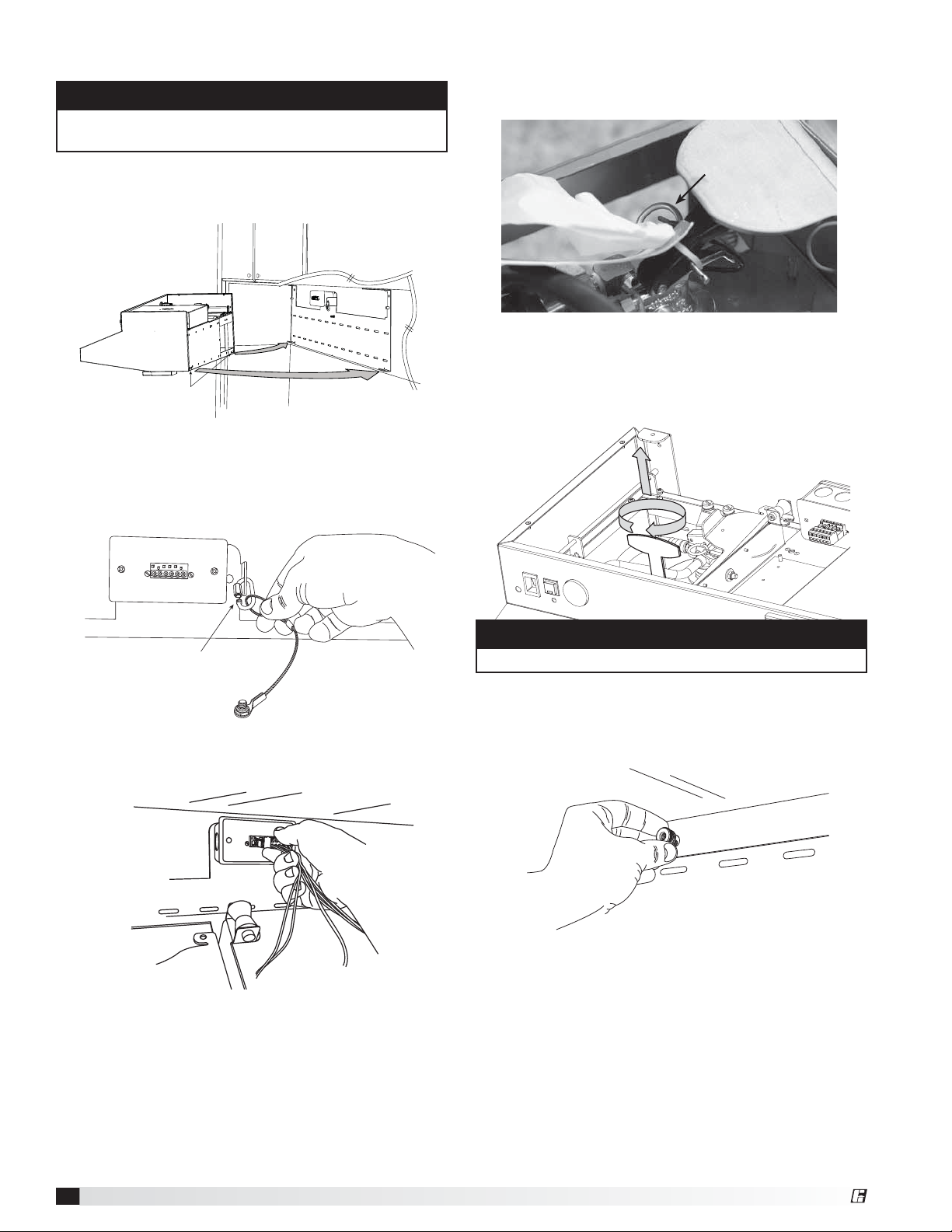
Static Pressure Testing - The magnehelic gauge test port opening is located
beneath the grease tray. The static pressure needs to be measured to ensure
airflows meet design criteria. The airflow is measured by attaching the gauge
tubing to the magnehelic gauge inlet, and the hood fitting is attached to the
grease drain hole beneath the grease tray.
A reading of 0.45 to 0.85 inches wg. is required to meet design standards.
This reading will correspond to the static pressure of the ductwork, hood
and fan combination.
®
Magnehelic Gauge
Magnehelic Gauge
Test Port
Test Port
Fire Ready Hood
5
Page 6
Fans
For inline fans and exterior wall fans, fan location and
proper mounting will be required.
If the hood system is configured for front recirculation
discharge or rear discharge and NFPA 101 compliance,
the unit will come equipped with a fan box. If installing
under cabinets, keeping the fan box flush to the
underside of cabinet will guarantee correct spacing.
Otherwise, center and mark the installation area
according to wall mounting bracket prior to hanging.
The following steps will be required.
1. Insert/attach the top portion of the manual pull kit
conduit through the fan box.
Accessories
Location restrictions will apply if the hood system
supplied is provided with any of the optional
accessories:
• ClockBox
• Remote ADA Switches
• Manual Pull Station
2. Attach square duct collar to the bottom of the fan
box with included hardware.
3. Attach the fan box to the mounting bracket with
included 8/32 nuts, then complete the installation on
the manual pull kit conduit and top/bottom unions.
When prepping a space for installation, a 4-
9
⁄16 inch
space must be allowed between the top of the mounting
bracket and the bottom of the cabinet for the fan box.
The additional height of the unit should not result in
reduced range clearance. Cabinets should be installed
approximately 5 inches higher to accommodate the
additional size of the NFPA 101 fan box assembly.
Fire Ready Hood
6
®
Page 7
Installation
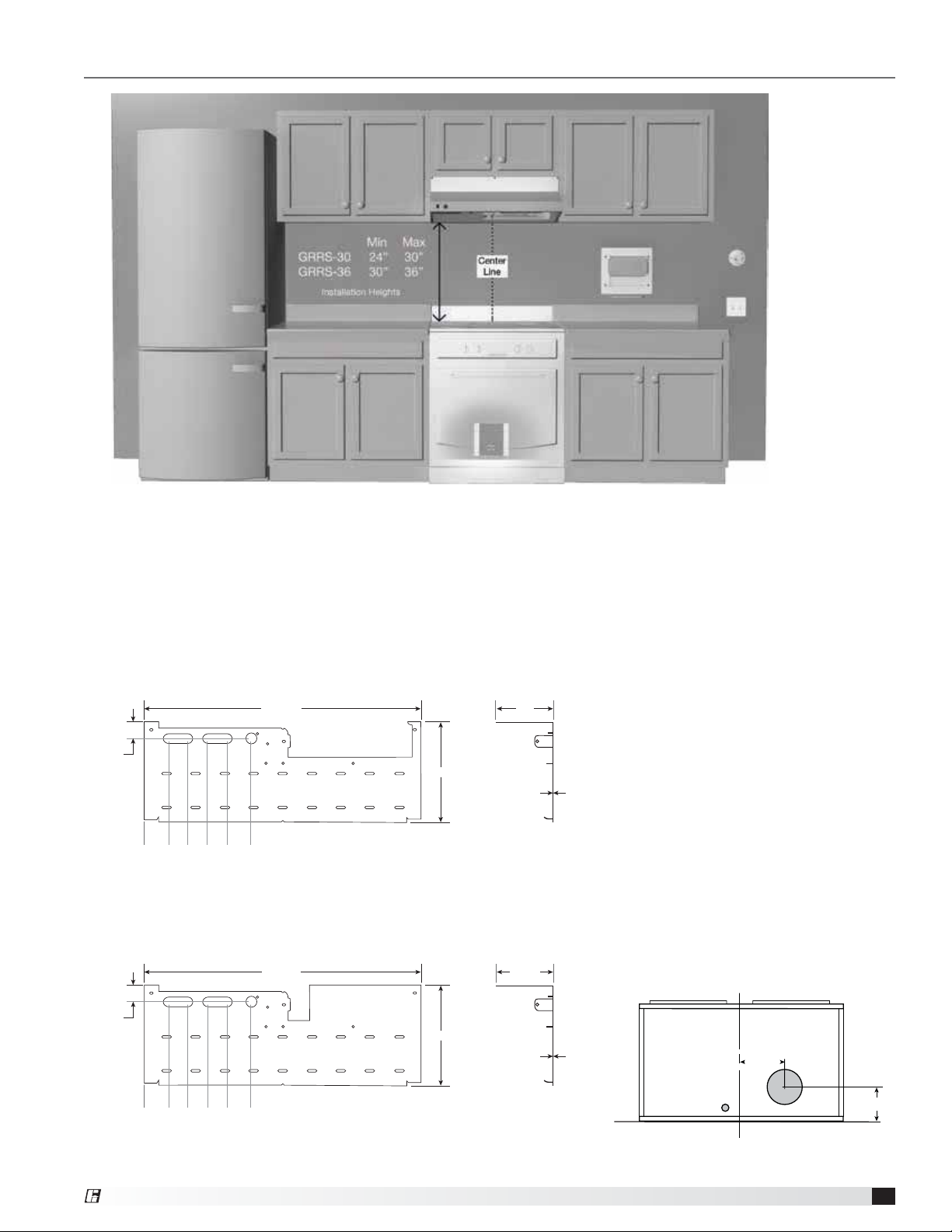
A
Installation Elevation
A. Hood (30 or 36 inches)
B. Appliance (for reference purposes)
C. Range Disconnect - electric, gas or dual (optional)
D. Gas Range Element Disconnect (not shown)
E. The ClockBox. Range Element Time-Out System (optional)
F. Handicapped Accessible Control Box (optional)
G. Manual Pull Station (optional)
Mounting Bracket for a 30-inch unit
28-5/8 in.
1-11/16 in.
B
DE
A
C
B
FFFFFFF
A
B
F
10-5/16 in.
0 in.
2-7/16 in.
4-7/16 in.
6-7/16 in.
8-7/16 in.
10-15/16 in.
Mounting Bracket for NFPA Installation
28-5/8 in.
1-5/8 in.
B
0 in.
2-1/2 in.
4-1/2 in.
DE
6-1/2 in.
8-1/2 in.
C
11 in.
A
B
A
FFFFFFF
B
F
10-5/16 in.
B
CD
4 in.
1/16 in.
5-7/8 in.
1/16 in.
E
G
F
Mounting Bracket
A. Center notches
B. Critical mounting points must be
secured to studs or drywall hangers.
C. Rear access to junction box
connection
D. Primary access point for
connections to junction box
E. Secondary access point for
connections to hood (options/
accessories)
F. Additional mounting points. Secure
minimum of three (3) screws per row.
Cabinet FrontCabinet Front
Cabinet Bottom
7-inch Round Duct
Access Hole
7-
13/16 in.
Electrical
Access Hole
C
L
5-15/16 in.
®
Fire Ready Hood
7
Page 8
Installing Hood onto Mounting Bracket
NOTE
Install manual pull station, if provided, before arming
the system.
4. Remove the safety pin - identified with the yellow
CAUTION flag from the trigger on top of the
extinguisher bottle.
1. Lift hood onto mounting bracket and seat the lower
tabs of the mounting bracket into slots in back of
hood.
Slots
Lower Tabs
2. While holding the hood up, hook safety cable to
chain link on mounting bracket and screw nut
to close the link. The hood is now in the service
position.
Safety Pin
5. Remove the safety key from the actuator arm by
rotating and lifting straight upwards. The system will
not actuate without completing steps 4 and 5.
Chain Link
3. Connect male plug from top of hood into female plug
mounted in junction box.
CAUTION
The system is now armed.
6. Rotate hood to wall and thread the three thumb nuts
to the bolts in the mounting plate. Check page 18 for
location of thumb nuts.
Fire Ready Hood
8
®
Page 9
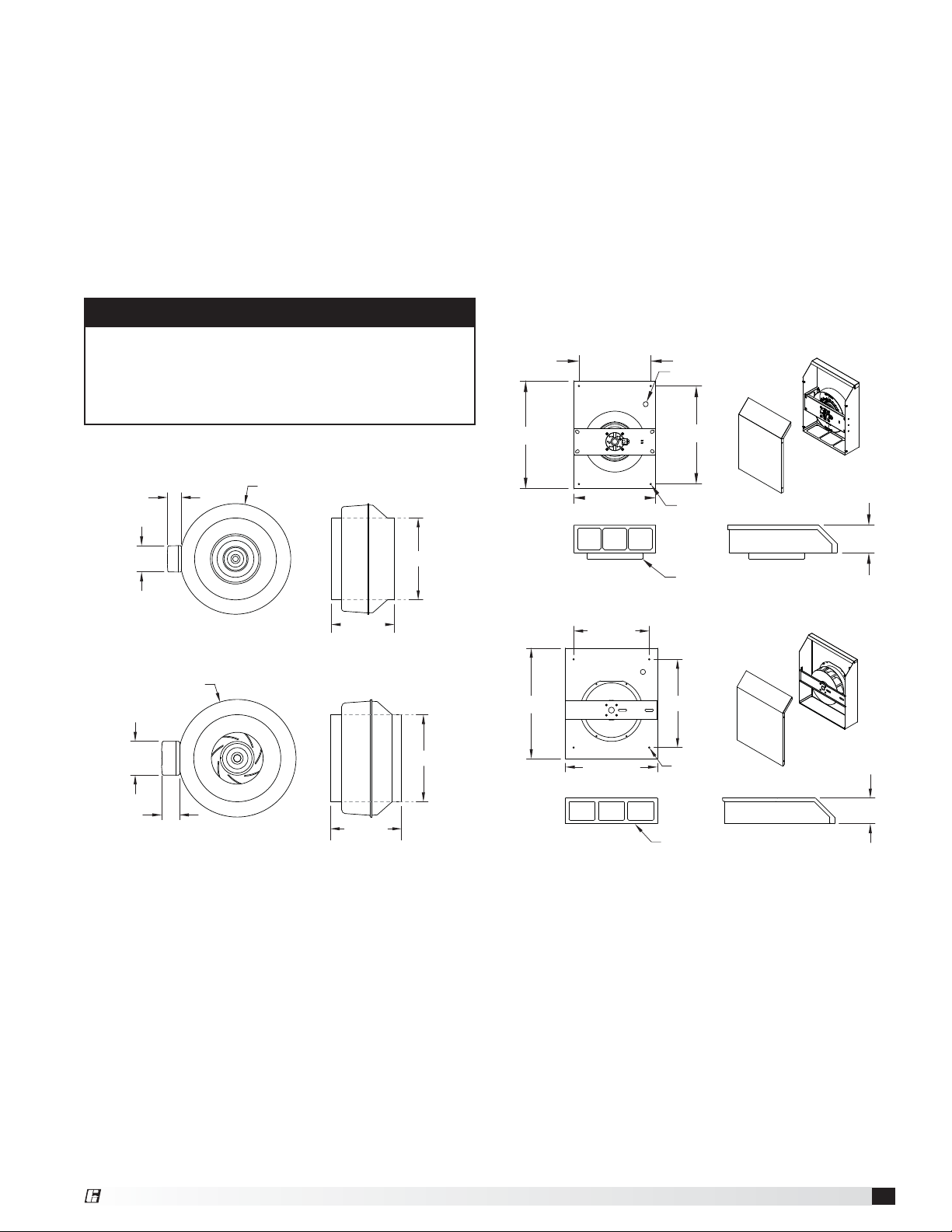
Installing Fan (if applicable)
Inline
Install fan vertically in ductwork running between the
unit and roof cap.
For best results, use as few elbows or transitions as
possible. If necessary, long radius elbows or bends are
recommended.
To attach ductwork, use duct tape at inlet and outlet to
assure a good seal. If using fan clamps, attach clamps
and insert screws through clamp into inlet and outlet
flanges.
CAUTION
Use sheet metal screws to secure ductwork to inlet
and outlet. It is critical that the screw penetrate the
metal of the flange, but not so far as to bind the
impeller. It may be necessary to angle screws away
from impeller.
Inline Exhaust Fan - NFPA
Wall Mounted Fan
Fasten the fan box to an external wall via the four
0.27-inch mounting holes.
Run electrical through the 0.81-inch hole towards the
top right corner of the box.
Attach ductwork using duct sealant, caulk, or tape
to all seams to prevent air leakage and maximize air
performance.
For best results use as few elbows or transitions as
possible. If necessary, long radius elbows or bends are
recommended.
Wall Fan - NFPA
11.625 in.
17.8125 in.
Ø0.81 in.
15.875 in.
2.4375 in.
3.75 in.
Ø16.00 in.
Inline Exhaust Fan - Non-NFPA
Ø13.375 in.
3.75 in.
2.00 in.
10.50 in.
8.25 in.
11.875 in.
10.00 in.
13.375 in.
Wall Fan - Non-NFPA
12.00 in.
17.50 in.
14.625 in.
Ø0.27 in. (4X)
MOUNTING HOLES
Ø8 IN. VENT DUCT CONNECTION
14.00 in.
Ø0.27 in. (4X)
MOUNTING HOLES
Ø8 IN. VENT DUCT CONNECTION
4.625 in.
4.0625 in.
®
Fire Ready Hood
9
Page 10

Range Element Disconnect Installation
Gas Disconnect Valve (if applicable)
The gas solenoid is designed for use with 3/4-inch NPT
pipe. Be sure to note the “IN” and “OUT” ends of the
solenoid body (as marked on the body). This determines
direction of gas flow. Refer to wiring diagram on pages
13 and 15 for details on electrical connection.
110 VAC Supply from Hood
- Electrical Connection
3/4-in. NPT
GAS FLOW
3/4-in. NPT
Electrical Disconnect Box (if applicable)
1. Cut a hole in the drywall for the relay box; refer to
the submittal for dimensions. Be sure to note the
1-1/4inch overhang on each side of the face plate.
Given this, the hole should be about 6-3/8 by 8-3/4
inch. The relay box has been designed to fit in a
standard 2x4 studded wall.
6-3/8 in.
8-3/4 in.
2. If you haven’t already done so, run wiring from the
junction box location (on the unit mounting plate) to
the power disconnect box location and string through
one of the knockouts in the box.
208-220 VAC
supply to appliance
120 VAC
120 VAC
from hood, black tape
from hood, black tape
3. Make all wiring connections and secure face plate to
box in wall. Wiring information is provided on pages
13 and 15.
Face P late
Fire Ready Hood
10
®
Page 11

Installing Accessories
Refer to your submittal for installation dimensions of
these accessories.
ClockBox (optional)
The ClockBox works by controlling the cooking element
(gas, electric and dual element ranges) and minimizes
the likelihood of an unattended cooking fire. The system
disables the cooking element until the operator unlocks
the cover and presses the GO button. After two hours
the cooking element is automatically disabled.
If this unit was provided with the ClockBox, a ClockBox
controller and Touchscreen user-interface will be
provided. Both will need to be remotely mounted near
the appliance (range) on a nearby wall.
Remote ADA Switches (optional)
If the unit is provided with the remote ADA switches,
these will have to be installed to be in compliance with
ADA standards for Accessible Design.
Manual Pull Station Installation (optional)
If the unit is provided with the remote ADA switches,
these will have to be installed to be in compliance with
ADA standards for Accessible Design.
Parts included in the kit:
Step 3: Install Cable and Pin to hood
Thread the cable through the conduit, with the pin
reaching the unit. Remove the grease filter. In the upper
right corner, find the two pulleys as illustrated. Hold the
rear-most pulley in
place. From the top
of the unit, replace
its pin with the one
on the cable. Push
the pin through the
pulley until you hear
it click in place. Go
back to the actuator
arm and rehook
cable onto the arm.
WARNING
You must allow for 8 to 12 inches of slack in the cable
to sit at the pull face. Failure to do so will cause the
unit to discharge the next time the unit is lowered into
its service position.
CAUTION
Make sure the cable does not become caught on any
part of the hood or conduit, or the cable will not be
able to be pulled, and the unit will not discharge.
Pull Box (x1)
Pull Face (x1)
Elbow Pulley (x3)
Cable and Pin (25 ft)
Step 1: Installing Conduit
Mount the pull box in an appropriate location according
to local building codes. Keep
in mind you are supplied with
25 feet of cable and three (3)
elbow pulleys. Install 1/2inch
conduit (not included)
Conduit attachment
to backplate
between the unit and the
pull box, using the pulleys as
needed. Pull cable through
the conduit, and allow 8 to
12 inches of slack to be left
at the hood unit end. Be sure
to abide by all local building
codes when installing
conduit.
Step 2: Replace Safety Pin and Key (to prevent
accidental discharge)
With the unit lowered
into its service position,
put the safety pin in
its slot at the top of
the extinguisher tank.
Also replace the safety
key in its slot in the
actuator arm. Then
remove the cable from
the actuator arm.
Step 4: Install Cable to Pull Face
With the unit in its lowered
position, attach the
cable to the pull face by
crimping a loop in the
cable through the hole
on the back side of the
handle. Be sure cable
is securely crimped to
Crimp
withstand at least 50 lbs.
of pull force. Leave no more than 12 inches of slack
in the line on the pull face end, but maintain 8 to 12
inches. To make this easier, the handle may be removed
by loosening the set screw in one of the studs, and
sliding the red plastic rod out. Attach the pull face to
the pull box already mounted on the wall, collecting
any slack into the pull box. Do not allow slack cable to
collect above the hood.
Installing Ductwork (optional)
Ductwork will need to be provided and installed if the
unit was provided with an external fan.
Installation work must be done by qualified person(s)
in accordance with all applicable codes and standards,
including fire-rated construction.
To minimize static pressure losses and promote
adequate airflow, minimize duct run lengths where
possible.
®
Fire Ready Hood
11
Page 12

Electrical Installation
Main Control Power
1. Determine mounting location of the appliance
disconnect (contactor box and/or gas valve) and
mounting bracket, if not already done.
2. Run factory-provided wire from junction box
through the wall to the appliance disconnect,
unless ClockBox option is provided. For electrical
installation information regarding the ClockBox, refer
to page 16. Wire the factory-provided 110 VAC main
power connection to a 15 amp rated circuit.
3. If the hood unit is to be linked to a fire alarm system,
accommodations for those wires will need to be
made at this time as well. Refer to fire alarm electrical
installation information on page 14.
Alarm Wire(s)
Alarm Wire(s)
NO/NC Local and Remote Alarm
NO/NC Local and Remote Alarm
by others
by others
CAUTION
Electrical installation should be performed by a
licensed electrician. Installation should be performed
according to all applicable codes and regulations. Shut
off power at the main breaker to prevent electrical
shock when accessing electrical connections.
All field installation and wiring of electrical equipment
must be done to meet NEC and local codes
Junction Box
Junction Box
with Connector
with Connector
Range Supply Line
208-220 VAC 50A max
supplied by others
Hood Supply 110-120 VAC 15A
Metal clad wire from 110-120 VAC supply line
12/2 8 ft length, marked with red tape
supplied by Greenheck
Run metal clad wire from junction box on mounting
plate to power disconnect box through wall
Metal clad wire from 110-120 VAC supply line
14/2 8 ft length, marked with black tape
supplied by Greenheck
Power disconnect mounted flush to wall
Power disconnect mounted flush to wall
50A 250V NEMA 14-50 receptacle
50A 250V NEMA 14-50 receptacle
supplied by Greenheck
supplied by Greenheck
Fire Ready Hood
12
®
Page 13

Electric Disconnect Box (if applicable)
50AMP 250V
NEMA 14-50
Wire Nut
Neutral
110 VAC Coil
50 AMP 208-240 VAC Single Phase
Supply Line (by others)
15 AMP 110-120 VAC
Supply Line (by others)
GND
N
Contactor 50A
L1
L3
Power Disconnect Box
H
8” x 6” x 4”
H
T1
T3
HH
Wire nut inside power
disconnect box
L1 208-220 VAC Black Hot
L3 208-220 VAC Red Hot
T1 208-220 VAC Black Hot
T3 208-220 VAC Red Hot
Green Ground
White Neutral
Black Hot
110-120 VAC 14/2
Metal Clad to 110-120 VAC
Power Disconnect
(Black Tape) - 14/2
Metal Clad Wire from 110-120 VAC
Supply Line (Red Tape)
By others
}
By Greenheck
}
Provided by Greenheck
Provided by others
Junction
Box
GND
NEUT
HOT
GND
NEUT
HOT
Back Support
Mounting Bracket
Green Ground
White Neutral
Black Hot 110-120 VAC
6 Position
Orange
Connector
6 Position
Grey
Connector
Supplied
}
Hood
Gas Disconnect Valve (if applicable)
110-120 VAC Gas Solenoid
15 AMP 110-120 VAC
Supply Line (by others)
Green
White
Black
Multiconductor
(4 Conductor)
Junction Box
Wire Nut
Metal Clad to 110-120 VAC
Power Disconnect
(Black Tape)
Green Ground
White Neutral
Black Hot 110-120 VAC
Metal Clad Wire from 110-120 VAC
Supply Line (Red Tape)
Green Ground
White Neutral
Black Hot 110-120 VAC
Junction
Box
GND
NEUT
HOT
GND
NEUT
HOT
Back Plate
6 Position
Orange
Connector
6 Position
Grey
Connector
Hood
®
Fire Ready Hood
13
Page 14

Inline/Wall Mount Fan Power (if applicable)
Twenty-five (25) feet of plenum rated wire is provided
with both the inline fan and wall mounted fan option.
The fan needs to be connected with the provided
connector within the hood controls. See wiring diagram
on page 15 for wiring information.
ClockBox (if applicable)
Twenty (20) feet of shielded control wire is provided with
the ClockBox option to connect the ClockBox controller
to the touchscreen interface. The ClockBox needs to be
connected back via the connector within hood controls.
See wiring diagram on page 15 for wiring information.
Remote ADA Switches (if applicable)
Eight (8) feet of shielded control wire is provided with
the ADA remote switch option. The switches need to be
connected back with the provided connector within the
hood controls. See wiring diagram on page 15 for wiring
information.
Fire Alarm System Connections
The hood unit has two fire alarm connections (discrete
switches), each with its own trigger. A connection is
made to one output (Y#) and one common (C#) at the
controller. The output labeled Y0 is triggered by a fault
from the high temperature switch (190°F), or pressure
switch, or hose switch. Output Y1 is triggered by a
high temperature switch (190°F) and a low pressure
fault in the extinguisher tank (the fire suppressant has
discharged). You may use either one connection or
both, depending on your situation. When there is a fault,
a buzzer in the unit will sound and the power disconnect
will turn off.
Local Alarm Connection: Connect to output Y0 and
common C0
Remote Alarm Connection: Connect to output Y1 and
common C1
To connect to the alarms, it is preferred that you use a
spade terminal connector (supplied), but a stripped wire
is acceptable.
Connecting the alarm system in the configuration
described above results in a normally open connection.
To switch these two alarm contacts to normally closed
connections, insert a jumper into the blue and the gray
terminal adjacent to it (terminal blocks 4 and 5). One
leg of the provided jumper is inserted into the blue
terminal and the other into the gray terminal.
Y0
Y1
C0
C1
Onboard Controller
In addition to the fire alarm system connections
described previously, a second connection may be
made to the fire alarm switch installed in the unit. Unlike
the connection above, this switch does not require
power to be fed to the hood in order to function. The
fire alarm switch is located above the actuator arm,
beside the controller assembly. The fire alarm switch is
activated when the actuator arm trips.
To connect the fire alarm switch, wire the fire alarm to
the common connector and normally open or normally
closed connection as shown.
Common
Normally Open
Normally Closed
Fire Alarm Switch
NOTE
Ensure jumper is inserted completely and the top of
the jumper is level with the other jumpers.
Fire Ready Hood
14
®
Page 15

Wiring Diagram
Description Value
CB ClockBox 2 HR
F1 Controller Fuse 1 AMP Fast Blow
F2 Fan Fuse 2 AMP Slow Blow
F3 Dual Disconnect 1 AMP Slow Blow
F3 Disconnect Fuse 0.5 AMP Slow Blow
F4 Main Fuse 8 AMP Slow Blow
F5 ClockBox Fuse 8 AMP Slow Blow
MP1 Main Power Connector
FP2 Fan Connector
SW1 Main Power Switch
SW2 Light Switch
SW3 Service Switch
SW4 Reset Switch
SW5 Optional ADA Light
SW6 Optional ADA Fan
HSW1 Hose Switch
HITH1 High Temp Thermostat 190°F
LOTH1,2 Low Temp Thermostat 150°F
FSP1 Fan Speed Controller 4.0 FLA
FAN Inline or Recirc Fan
CAP1 Capacitor for Recirc Fan 10 UF
M1 Stove Disconnect 40 FLA 50 A RES
LIGHT Hood Light 60 WATT
Controller Computer Driving Hood
BUZZER Alarm in Hood 90 DB
®
Fire Ready Hood
15
Page 16

ClockBox Wiring Diagram (if applicable)
CLOCKBOX
Green
GND
120VAC
INPUT
Supply Line
White
N
Black
H
T5
T3
T4
Fuse
5.5 Amps
L N GND -V +V
POWER SUPPLY
Blue
24 VDC
Brown
T5
Green/
Yellow
Circ DIN
(NEG)
(POS)
PLC
Y0
Y1
Y2
Y3
COM
Y4
COM
Y5
COM
1. An independent 110 VAC supply line is provided to
the ClockBox.
a. This supply line provides power to the ClockBox,
which is independent from the supply line to the
hood.
2. The ClockBox provides 110 VAC to the Power
Disconnect Assembly
3. The ClockBox provides control signal voltage (5VDC)
and logic control to the Touchscreen [HMI]
4. The Power Disconnect Assembly supplies the input
line to the stove/range as follows:
a. If an Electric Disconnect
- Controls the 110 VAC contactor coil allowing the
220 VAC supply line to the stove/range via the
NEMA 14-50 receptacle.
b. If a Gas Disconnect
- Open the solenoid valve allowing gas to flow to
the input line of the stove/range
c. If Dual Disconnect
- Both conditions 6.a.i and 6.b.i will apply
d. The above reference will be maintained for as long
as there is time left at the ClockBox, it will open
the contact in the timer, stopping the supply line
to the Power Disconnect, which in turn, will shut
off the stove.
Black
Black
5 VDC
Black
White
Green
T5
T4
T1
T2
H
A1
PWR DISC
OUTPUT
Supply Line
White
Brown
Green
Black
Red
H
N
GND
N
A2
1 - SG
2 - SD
3 - RD
4 - (NEG)
5 - (POS)
HOOD 120VAC
INPUT
Supply Line
TOUCH
SCREEN
ClockBox System Interface Diagram
110VAC
110VAC
Supply Cable
Supply Cable
110VAC to Hood110VAC to Hood
110VAC
110VAC
Supply Cable
Supply Cable
Communication
Communication
Clock
Clock
Box
Box
110VAC to
110VAC to
Disconnect
Disconnect
5VDC
5VDC
Wire
Wire
ClockBox
ClockBox
Touchscreen
Touchscreen
NOTE
Some electric stoves/ranges have a warning light
to alert the user that the burners/coils are hot.
These warning lights will be off since the supply line
powering the stove/range is not present.
Fire Ready Hood
16
®
Page 17

Operation - How it Works
The GRRS functions as a standard ventilation range
hood with the added capability to suppress stove top
fires.
Designed for use over a standard 30 and 36 inch
residential range, it uses a mechanical, commercial style
automatic fire suppression system.
Refer to the illustration below to familiarize yourself with
the following functions.
• A controller provides an internal alarm plus
connections for up to two external alarms that may go
to a local alarm panel and/or remote location, i.e. the
local fire department.
• The unit is powered from standard 115 VAC / 60 Hz /
single phase. A main Power Switch is located at the
upper left of the front surface. (Remote ADA switches
provided).
• For normal daily use, the unit provides a fan speed
control knob and a light switch for the light.
• A Reset Button (white) is provided to energize the
controller and the main power disconnect contactor
(electric range) or valve (gas stove). Upon initial power
up, the control system is not enabled and this reset
button needs to be pressed. In doing so the Status
LED below the reset switch will turn from red to green.
Environmental Monitoring / Pre-Suppression
Functions
The controller operating system is designed to enhance
the functionality of the unit and the safety of the cooking
environment.
The system relies on input from a set of thermostats to
control the fan and shutoff power to the stove when the
temperature reaches preset points.
As the temperature rises, the controller monitors the
environment with the three (3) thermostats. The board is
programmed to respond to two temperature thresholds.
The first at 150°F and the second at 190°F.
At the first temperature threshold of 150°F, the
ventilation fan will turn on, regardless of the front
panel switch setting.
At the second temperature threshold of 190°F:
1. The power disconnect to the stove (valve or
contactor) is de-energized, shutting off power to the
stove.
2. The “local” alarm output is tripped, indicating a
trouble condition with the unit. This output is from
contacts C0 and Y0 on the controller.
3. The on-board audible alarm sounds (high pitched
tone).
NOTE
See page 21 for controller schematic.
®
Fire Ready Hood
17
Page 18

Accessing the Internal Components
Thumb nut locations
fo
f
l
y
y
Moving the unit between ‘operating’ and ‘service’
positions.
All GRRS models have been configured as a stand
alone unit mounted to a wall plate. As such, the unit
may easily be tilted down into a service position, giving
you access to the electronics and extinguisher tank, or
be removed completely for maintenance and cleaning.
Provisions have been made to facilitate easy removal
including a minimal amount of fasteners and modular
electrical connections.
To place the unit in the service position, a few simple
steps are required. Be sure to wear safety glasses at all
times during this process:
1. Shut the unit off with the power switch on the front of
the hood.
2. Remove the grease tray and the grease entrapment
filter.
3. For non-ducted installation, loosen and remove
the thumb nuts that are on the rear inside wall of fan
housing compartment.
CAUTION
• Be careful while working with the unit in the service
position. Release of the cable system or applying
force to the tank valve assembly may cause
discharge of the tank. The high pressure discharge
has the potential to cause skin or eye damage and
injury!
• An electrical shock hazard is present at the
electrical compartment whenever there is power to
the hood. Use caution when working around this
device while the unit has power.
Three thumb nut locations
for non-ducted fan
On ducted installations, remove the two thumb nuts
located at the top inside near the fan intake. Slowly
lower the unit.
r ducted fan on
4. The unit will now freely pivot downward to a stop
position. A safety cable is provided to prevent the
unit from falling or lowering too far.
5. Place safety pin in the tank valve to avoid accidental
discharge.
With the unit in this position, basic servicing and
cleaning may be performed, including servicing the
extinguisher tank assembly.
To move the unit back to the operating position, simply
reverse the process as outlined above.
Fire Ready Hood
18
®
Page 19

ClockBox Operation and Navigation (if applicable)
FIGURE 1
1. Press Start/Reset to allow the
2 hour timer to begin. This will
prompt to the password screen.
See Figure2.
2. Press Pause to pause the timer,
press again to continue.
3. Press STOP to stop the timer.
4. If the timer is running, pressing
the Start/Reset button will reset
the timer at the original timer value
and start running the timer again.
5. The Greenheck logo is a hidden
button which allows access to
background menus. Press the
Greenheck logo to access hidden
menu to modify timer values and
passwords. See Figure 3.
NOTE: Main Screen will always
show available time. System is preset to countdown remaining time.
FIGURE 2
1. Factory preset master password:
06412
2. Enter password 06412 and then
press the enter symbol ().
FIGURE 4
1. To adjust hours, minutes, or
seconds of cook timer, press on
respective number. Enter the new
value and press enter symbol ()
to store the value.
FIGURE 5
1. Adjust pasword number and level.
Press under New Pass to key
new password. To validate the
password, re-type the password
under Re-Type Pass. Press the
Change/Add key to add or adjust
a password or Delete to omit a
stored password.
FIGURE 3
1. Press Timer Mgmt to modify the
timer value. See Figure 4 for timer
management screen.
2. Press Password Mgmt to add/
modify/delete passwords.
See Figure 5 for password
management screen.
®
Fire Ready Hood
19
Page 20

Test Tank and Demonstration
Once the hood has been installed, it may be necessary
or desired to test the unit with a test tank filled with
pressurized nitrogen (optional).
1. Following the “Removing the Extinguisher Tank”
instructions on page 25, remove the extinguisher tank
and replace it with a test tank.
WARNING
The safety pin must be in place in the extinguisher
tank until the unit is ready to be returned to service
or to be tested. Always wear safety glasses during
this procedure.
2. The unit can be actuated one of two ways:
A. Cut Test Links
Replace the actuator arm’s safety key. Loosen the
turnbuckle in the fusible link cable assembly (underside
of hood). Replace one of the fusible links with a test link.
Retighten the turnbuckle to the proper tension. Remove
the safety key and raise the unit to its operational
position. To test, cut the test link with wire cutters or
similar.
Safety Pin
B. Manual Pull Kit (if installed)
Raise the unit to its operational position after the test
tank has been installed. Remove the plastic break rod
from the pull face with an allen wrench (refer to manual
pull station appendix for
more detailed information
on this). Pull the handle
to actuate the unit. Refer
to the “Manual Pull Kit”
section on the method to
return the pull station to an
operational state.
3. Nitrogen should be released from each nozzle
simultaneously.
WARNING
Be careful of the protective caps on the nozzles.
These will fly off the nozzles when the unit is actuated.
Always wear safety glasses during this procedure.
4. Replace the test tank with the extinguisher tank, the
test link with a fusible link, and place the unit to its
operational position. The unit is now ready to be put
into service.
Safety Key
Turnbuckle Fusible Link
Fire Ready Hood
20
®
Page 21

Controller Schematic
On the controller, there are two rows of LED indicators
next to the X (inputs) and two rows of LED’s on the Y
area (outputs).
LED
Label
X0
X1
X2
X3
X4
Input
Function
Hose
Switch
Reset
Switch
Pressure
Switch
Service
Switch
Low
Temperature
Switch
Scenario
Hose in place On
Hose disconnected Off
When switch is depressed On
Switch not pressed Off
Pressure okay On
Pressure failure Off
Servicing unit On
Normal operation Off
Both low temp thermostats
below 150°F
Either thermostat at or above
150°F
Alarms are configured for
normally closed (jumper
installed)
Alarms are configured for
X5
Remote
and
Local Alarms
normally open (no jumper)
High temperature thermostat
below 190°F
High temperature thermostat
at or above 190°F
Scenario
X6
LED
Label
High
Temperature
Switch
Output
Function
Low gas switch activates OR
Y0
Output for
Local Alarm
hose switch activates OR high
temperature switch activates
Normal operation Off*
Loss of pressure AND high
temperature (fire suppression
discharge)
Normal Operation Off*
Alarm condition On
Normal condition Off
Y1
Y2
Output for
Remote
Alarm
Normal
Condition
When controller turns the fan
Y3 Fan
on
When controller is not running
the fan
When power is being set
to gas/electric disconnect
(normal operation)
When power is lost to gas/
Y4
Power
Disconnect
electric disconnect
Y5 Horn
Horn is on On
Horn is off Off
* The LED’s state depends on whether the alarm contacts are
set up for normally open or normally closed. These contacts
are set up for normally open from the factory (LED’s illuminate
during alarm). To configure the fire contacts for normally
closed state (LED’s illuminate on no alarm), a jumper must
be placed between two terminals. Please see page 14 for
additional information.
LED
State
On
Off
On
Off
On
Off
LED
State
On*
On*
On
Off
On
Off
Status display
Input/output
display
RUN
0
X
0
Y
4
PROG.
5
ERR.
3
74
3
COM
LN
X0 X2 X4 X6
RUN PROG. ERR.
0
3
X
74
0
3
Y
4
5
Panasonic
RUN
FP-X C14
PROG.
max.min.
V1
V0
Y1
Y0
0V
24VY5C0C1C2 C3 Y4
X1
X3 X5 X7
Y3Y2
The controller’s operating system is designed to
enhance the functionality of the unit and the safety of
the cooking environment.
Alarm Connections
Alarm Outputs: The other function of the controller
is to report alarms from the system either for a system
fault or as a result of a system discharge. Refer to
Fire Alarm System Connections on page 14 in this
installation manual for information on how to connect
the alarm outputs.
Output Y1 and common C1 are configured to close with
the discharge of the extinguisher tank. This condition is
determined by the controller with the low pressure input
from the switch and a high temperature condition from
the 190°F rated thermostat. Both conditions must be
present in order for this output to trigger.
Note that the microswitch outputs are dry contact type,
rated for low voltage, and can be normally open (NO) or
normally closed (NC), with a common. Therefore do not
produce any current or voltage output.
NOTE
Pressing the reset button will not turn off alarm. Unit
needs to be recharged to reset alarm.
Service Switch: The black switch next to the controller
and internal audible alarm is the service switch. It can
be switched on or off. When it is switched to on, the
remote alarm and local
alarm are deactivated. Its
purpose is to allow service
to be conducted and
components tested without
setting off the alarm. Once
testing or service is done,
turn the service switch to
off for normal operation.
NOTE: LED will flash orange
and green.
Service Switch
in the OFF position
®
Fire Ready Hood
21
Page 22

Self-Monitoring System
These functions are to be checked at start-up.
Low Pressure
HOW TO TEST FUNCTION
a. Unplug one of the wire terminal connections
attached to the pressure switch.
b. LED turns from green to orange blinking with buzzer.
c. Power for gas valve or disconnect turns off.
d. Audible buzzer inside of hood beeps 4 times.
e. Local Alarm Activation “Y0-C0”.
f. Hood remains powered.
Loose Connection on Discharge Hose
HOW TO TEST FUNCTION
a. Unplug the hose quick disconnect coupling to
discharge manifold.
b. LED turns from green to orange blinking with buzzer.
c. Power for gas valve or disconnect turns off.
d. Audible buzzer inside of hood beeps 3 times.
e. Local Alarm Activation “Y0 to C0”.
f. Hood remains powered.
High Temperature Switch
HOW TO TEST FUNCTION
a. Unplug red wire terminal located on terminal strip
#4. NOTE: Do not remove the wire, just unplug the
terminal. You can also use a heat gun on the center
of the hood to simulate a high temperature.
b. LED turns from green to orange blinking with buzzer.
c. Power for gas valve or disconnect turns off.
d. Audible buzzer inside of hood beeps 5 times.
e. Local Alarm Activation “Y0 to C0”.
f. Fan turns on.
g. Fan remains on for 3 minutes after you lower
temperature or put red wire back on.
h. Hood remains powered.
Low Temperature Switches
HOW TO TEST FUNCTION
a. Use heat gun on either left or right low temp switch.
b. Fan turns on.
c. Fan remains on for three minutes after temperature
falls below 150ºF.
High Temperature and Low Pressure Switches
HOW TO TEST FUNCTION
a. Unplug red wire terminal located on terminal strip
#4. NOTE: Do not remove wire, just unplug it’s
round connector. Unplug one of the wire terminal
connection attached to pressure switch.
b. Fan turns on.
c. LED turns from green to orange.
d. Power for gas valve or disconnect turns off.
e. Audible buzzer inside of hood on continuously.
f. Local Alarm Activation “Y0 to C0”.
g. Remote Alarm Activation “Y1 to C1”.
h. Hood remains powered.
Alarm Discharge Switch
HOW TO TEST FUNCTION
a. Depress actuator lever located at the micro-switch
next to tank.
b. Check continuity of both normally open and closed
contacts.
Service Switch in ON (1) Position
HOW TO TEST FUNCTION
a. LED turns from green to blinking orange/green.
b. Power for gas valve or disconnect turns off.
c. No alarm closure at Y1-C1 or Y0-C0.
d. Pressing the reset button will not reset the hood
until the service switch is put back in the off (normal)
position.
Fire Ready Hood
22
®
Page 23

After an Actuation
The fire suppression system must be recharged and
restored to service immediately after any discharge for
continued fire suppression protection.
WARNING
• Safety glasses and gloves must be worn for all the
following operations. Flush thoroughly with clean
water if agent comes in contact with skin or eyes.
• Allow time for cooling before attempting any
cleaning. Using water to clean any appliance that
contains hot grease or cooking oils, may result in
violent steaming or splattering.
Clean-Up Procedures
Due to the alkaline nature of the fire suppressing agent,
kitchen surfaces must be cleaned immediately after
system discharge. The wet chemical agent discharged
produces a foamy by-product that can be wiped up with
a cloth or sponge.
Clean-up procedures are as follows:
1. Before clean-up ensure that all fuel or electrical
sources to the equipment to be cleaned have been
shut off. Unplug exhaust hood and all appliance
electrical controls to avoid any chance of electrical
shock resulting from the cleaning process or from
an electrically conductive liquid agent.
2. Discard food and cooking oil that has contacted the
extinguishing agent since it is no longer suitable for
consumption.
3. Wipe up as much of the agent as possible with
paper towel or disposable rags.
4. Use hot, soapy water to clean away all residue and
any surfaces that the agent has come in contact
with.
5. Completely dry all areas before continuing the
service procedure.
Inspect the Unit for Damage
Be sure no components of the hood were damaged
from fire/heat.
Determine Cause of Discharge
Determining the reason for the system discharge before
recharging the fire suppression system and resetting the
unit is critical to ensure either the system performed as
designed, or was caused by a component malfunction.
Great care has been taken to simplify field installations,
so system malfunctions should be extremely rare.
• A fire may have caused the fusible links to melt,
causing the system to discharge. In case of fire,
inspect the electrical system and all wiring for heat
damage.
• The remote pull station (optional) may have been
pulled.
• If fusible links have not been changed within the past
12 months, they may have stretched and released the
actuation cable.
How to Reset the Suppression System
Resetting and testing release mechanisms, remote
pull, and fusible links.
Reset detection system by completing the following
steps:
1. Remove extinguisher tank
2. Make sure tension arm cable is in the released slack
position.
3. Remove the 3 fusible links from the cable assembly
and replace links with 2 new properly rated links
and one test link at terminal end.
4. Return tension arm and cable mechanism to a
cocked position.
5. Using wire snips, cut the test link at the terminal end
to simulate an actuation.
6. If system actuates successfully, go to Step 8.
7. If the release mechanism does not actuate, check
the following components and remedy any disorder
as follows:
a. Check the detector links for correct positioning
through pulleys in system and for possible twists
or knots in the cable
b. Ensure that actuator arm is in place and is
cocked.
c. Retest the system after installing a new test link
on the terminal end.
d. Verify that safety pin is removed from suppression
tank. If problems persist call the factory at 1-800371-6858.
8. Upon successful actuation of the system, complete
the following steps:
a. Release cable from actuation lever and install a
properly rated fusible link in the terminal location.
b. Replace extinguisher tank and reattach cable to
actuation lever to place it into its “ready” position.
Recharge Tank
1. Placing the hood into the service position allows for
removal of tank and examination of components.
2. Disconnect the tank pressure switch and the hose
discharge assembly connection and remove the
tank from the hood. It is recommended to replace
the pin back into the tank in case of left over
suppression media.
3. Remove the tank valve assembly and inspect the
valve and O-rings for damage. Thoroughly flush the
valve and O-ring with water.
4. Once flushing is complete, refill the tank with
the measured amount in the recharge and refill
kit, screw on valve assembly, and recharge with
nitrogen to a pressure of 100-105 psi (green zone on
pressure gauge).
5. Reinstall tank and ensure all systems have been
thoroughly checked and retested with new links.
The system can now be put into service.
®
Fire Ready Hood
23
Page 24

The pressure gauge is directly plumbed to the wet
chemical tank valve assembly and indicates the
pressure status of the nitrogen in the tank. The tank
includes a pressure switch that closes if pressure is in
the “green” or normal operation range.
Resetting Gas Shut-Off Valve
Before the gas supply is turned back on, extinguish any
open flames and turn off all burners and any electrical or
mechanical devices that are capable of igniting gas to
reduce the risk of explosion due to leaking gas. Check
to ensure the power switch is on.
Reset gas shut-off valve by completing the following
steps:
1. On the top of the hood press the white manual reset
button. The gas valve will energize into its normal
operating (open) position.
2. Examine burners for gaseous odor. If gas odor exists,
turn off power switch which will cause the gas valve
to close and shut off gas supply. Clear gas fumes by
opening windows and doors and then correct gas
leak before proceeding.
3. Reset gas valve again and if there is no gaseous
odor, pilot lights may be ignited at this time. Gas
stoves with a pilot light that is always on require
added caution. The pilot light must be relit manually.
Resetting Electrical Relay Shut-Off
1. Check to ensure the power source is on.
2. Press the white manual reset switch on the top of the
hood.
3. Status LED will turn from red to green.
If the system does not reset, one of the following
possibilities may be the problem:
• Tank hose not connected properly
• Tank pressure sensor wire disconnected
• Tank not to adequate pressure
• Electric power is shut off
Fire Ready Hood
24
®
Page 25

Maintaining the System
Pressure
Ga
ug
g
e
rg
e
e
Ho
se
S
Sa
ty
Pi
Tan
Valve
Presure
Sw
w
h
MoMoununti
ng
g
Bracke
t
Actuator a
undede
sio
ininreaea
dy
dy
p
p
it
ioio
n
Cleaning the Hood
To remove built up grease and cooking debris, clean
the unit thoroughly with mild detergent and water. Be
careful when using abrasive cleaning pads as they may
scratch or mar the stainless steel surfaces. The grease
entrapment filter, front discharge grille and grease
tray are dishwasher safe. The carbon filter cannot be
washed and should be replaced periodically as needed.
Inspection Procedures
Inspect the Nozzle Caps
The nozzle caps should be inspected and cleaned. All
five (5) nozzles should have protective caps installed.
If necessary, remove the caps and check for build up
of debris or any signs of clogging of the nozzle orifice.
If clogging is suspected, remove the nozzle with a
7/16-inch wrench, and flush with hot water until it flows
freely through the nozzle.
Replace the nozzle and protective cap.
Replacement caps and nozzle O-rings are available
from Greenheck or through your representatives.
WARNING
The protective caps stay on the nozzles at all times. In
the event of a discharge, the caps will blow off.
Inspect Fusible Link System*
Periodic inspection of the fusible link system ensures
the unit is ready to work in the case of a fire.
1. Place safety pin
in tank valve.
2. Remove tank
from hood.
3. Remove tension
from cable
system by
loosening the turnbuckle.
4. If the fusible links need to be replaced, call 1-800355-5354 or contact your representative.
5. Inspect pulleys and cable. Pulleys should rotate freely
and cable should be flexible. Everything should be
free of grease build-up.
6. Tighten the turnbuckle, reapplying tension to the
stainless steel rope, making sure the cable is running
through the pulleys properly and there are no kinks or
knots.
7. Reposition the tank.
8. Remove safety pin from tank valve.
*Each fusible link is date-stamped and must be replaced
if expired or after 12 months of use.
WARNING
If grease build-up on the cable system is not kept to
a minimum, the cable could become stiff and will not
discharge the suppressant in the event of a fire.
r ten
rm
n
os
10 Year Maintenance
Hydrostatic testing and new liquid agent, or tank
replacement is recommended at ten-year intervals. The
manufactured date is stamped on the top of the tank.
This should be performed by an authorized technician
or at the manufacturer’s facilities. Material safety data
sheets are available from Greenheck.
WARNING
Rubber gloves and safety glasses should be worn
during service or inspection of the tank. If contact
with the chemical agent skin or eyes occurs, flush
immediately with water for 15 minutes. If irritation
persists, contact a physician. If taken internally, do not
induce vomiting. Dilute with water or milk and contact
a physician.
Lighting
Illumination is provided by a 60 watt medium-base
shatterproof incandescent light bulb. To replace, make
sure the light switch is in the “OFF” position and then
gently unscrew the bulb. (Bulb: 60A15/TF)
Removing the Extinguisher Tank
1. Lower the hood to its service position
2. Insert the safety pin in the valve head so that
accidental release of the suppressant does not occur.
3. Unplug the pressure switch wire and move it out of
the way for now.
4. Disconnect the discharge hose from its fitting located
inside the unit closest to the user.
5. Unscrew the two wingnuts holding the bracket for the
tank.
6. Lift the tank out of the hood.
7. To replace the tank, simply reverse these steps.
fe
n
itc
Discha
®
Fire Ready Hood
25
Page 26

and Recertification Schedule
WARNING
Safety glasses must be worn whenever service
operations are performed.
Monthly Annually
Cleaning Yes Yes
Suppression Nozzles Inspect Inspect
Fusible Links Inspect Replace
Extinguisher Tank Inspect Recertify Replace
Every
10 years
Replacement PartsRecommended Service
Part
Number
479683
479684
479685
479686
479687
479688
479689
479690 Fire Ready 60W Shatterproof Bulb, pack of 2
479691 Fire Ready Fusible Links, 212°F, 3 links
479692 Fire Ready Fusible Links, 280°F, 3 links
479693 Fire Ready Nozzle Caps, set of 10
479694
479695
479696
479697 Fire Ready Grease Entrapment Filter
479698 Fire Ready Grease Filter Cup
479699
Description
Fire Ready Annual Service Kit
(3) Links and Service Tag
Fire Ready Recharge Kit
Tank Assembly fully charged with adapter
Fire Ready Test Kit, Tank Assembly
Nitro only with adapter and test link
Fire Ready Tank Kit, Tank Assembly
Empty with adapter
Fire Ready Test Kit
Set of 2 Test Links, 4 Nozzle Caps and
1 Safety Key
Fire Ready Electrical Disconnect Box
208-240VAC/50A (as replacement)
Fire Ready 3/4-inch Gas Valve
115VAC (as replacement)
Fire Ready Wire Rope Assembly Set
Hood Width of 30 inches
Fire Ready Wire Rope Assembly Set
Hood Width of 36 inches
Fire Ready Replacement Charcoal Filters
“F” Calibrations, pack of 10
Fire Ready Replacement Fuse Kit for Control
Systems
Fire Ready Hood
26
®
Page 27

Maintenance Log
Date ___________________Time _____________ AM/PM
Notes: ___________________________________________
_________________________________________________
_________________________________________________
_________________________________________________
_________________________________________________
Date ___________________Time _____________ AM/PM
Notes: ___________________________________________
_________________________________________________
_________________________________________________
_________________________________________________
_________________________________________________
Date ___________________Time _____________ AM/PM
Notes: ___________________________________________
_________________________________________________
_________________________________________________
_________________________________________________
_________________________________________________
Date ___________________Time _____________ AM/PM
Notes: ___________________________________________
_________________________________________________
_________________________________________________
_________________________________________________
_________________________________________________
Date ___________________Time _____________ AM/PM
Notes: ___________________________________________
_________________________________________________
_________________________________________________
_________________________________________________
_________________________________________________
Date ___________________Time _____________ AM/PM
Notes: ___________________________________________
_________________________________________________
_________________________________________________
_________________________________________________
_________________________________________________
Date ___________________Time _____________ AM/PM
Notes: ___________________________________________
_________________________________________________
_________________________________________________
_________________________________________________
_________________________________________________
Date ___________________Time _____________ AM/PM
Notes: ___________________________________________
_________________________________________________
_________________________________________________
_________________________________________________
_________________________________________________
Date ___________________Time _____________ AM/PM
Notes: ___________________________________________
_________________________________________________
_________________________________________________
_________________________________________________
_________________________________________________
Date ___________________Time _____________ AM/PM
Notes: ___________________________________________
_________________________________________________
_________________________________________________
_________________________________________________
_________________________________________________
Date ___________________Time _____________ AM/PM
Notes: ___________________________________________
_________________________________________________
_________________________________________________
_________________________________________________
_________________________________________________
Date ___________________Time _____________ AM/PM
Notes: ___________________________________________
_________________________________________________
_________________________________________________
_________________________________________________
_________________________________________________
®
Fire Ready Hood
27
Page 28

Our Commitment
As a result of our commitment to continuous improvement, Greenheck reserves the right to change specifications
without notice.
Specific Greenheck product warranties are located on greenheck.com within the product area tabs and in the
Library under Warranties.
Greenheck’s Fire Ready Residential Range Hood, Model
GRRS catalog provides additional information describing the
equipment, available accessories, and specification data.
®
Phone: 715.359.6171 • Fax: 715.355.2399 • Parts: 800.355.5354 • E-mail: gfcinfo@greenheck.com • Website: www.greenheck.com
GRRS, Rev. 2, December 2014 Copyright 2014 © Greenheck Fan Corporation
28
AMCA Publication 410-96, Safety Practices for Users and
Installers of Industrial and Commercial Fans, provides
additional safety information. This publication can be obtained
from AMCA International, Inc. at www.amca.org.
 Loading...