

Page 1
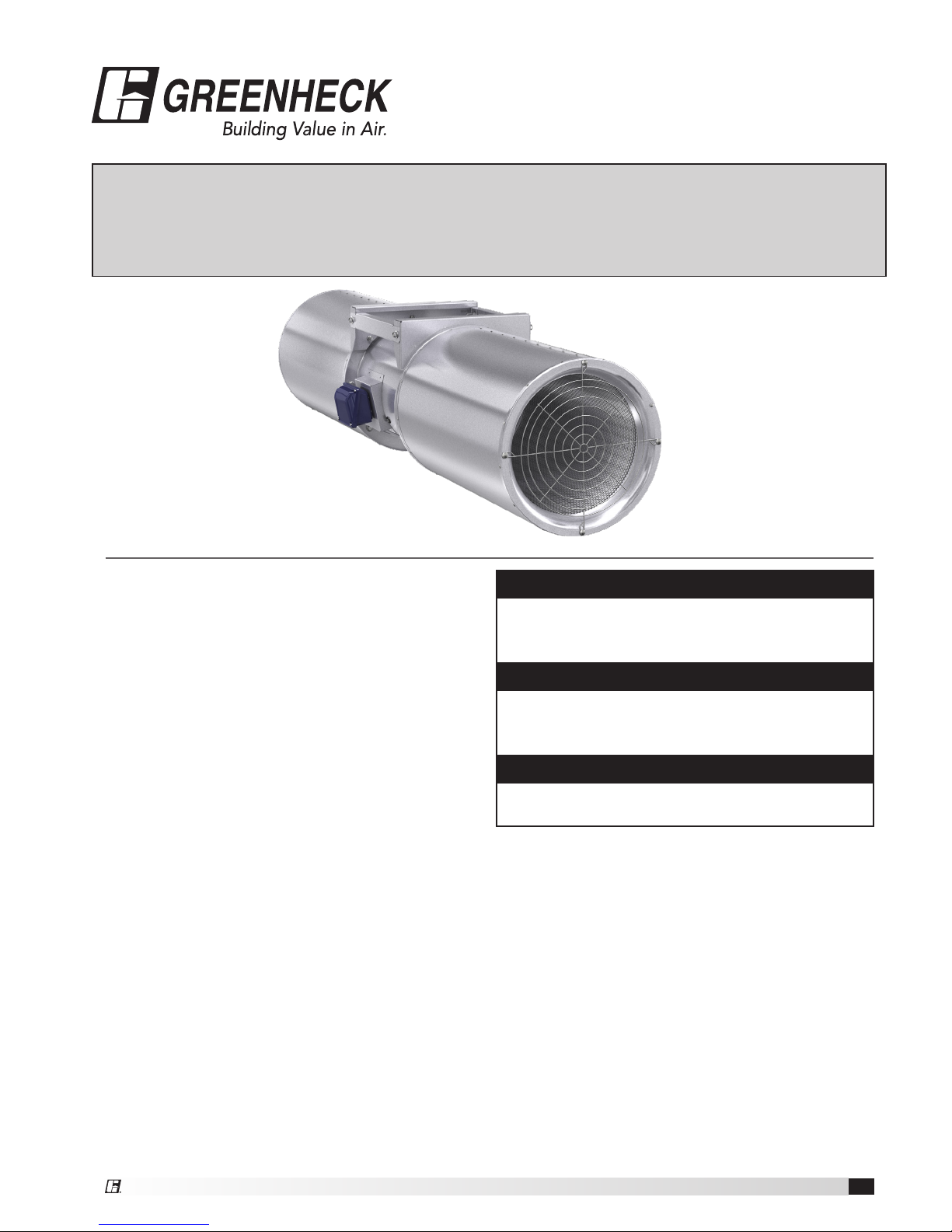
Installation, Operation and Maintenance Manual
Please read and save these instructions for future reference. Read carefully before attempting to assemble,
install, operate or maintain the product described. Protect yourself and others by observing all safety
information. Failure to comply with instructions could result in personal injury and/or property damage!
1
Jet Fan
®
Document 480189
Model GJ
Only qualied personnel should install this unit.
Personnel should have a clear understanding of these
instructions and should be aware of general safety
precautions. Improper installation can result in electric
shock, possible injury due to coming in contact with
moving parts, as well as other potential hazards.
Other considerations may be required if high winds
or seismic activity are present. If more information
is needed, contact a licensed professional engineer
before moving forward.
1. Follow all local electrical and safety codes, as well
as the National Electrical Code (NEC), the National
Fire Protection Agency (NFPA), where applicable.
2. The rotation of the propeller is critical. It must
be free to rotate without striking or rubbing any
stationary objects.
3. Motor must be securely and adequately grounded.
4. Do not spin fan propeller faster than the maximum
cataloged fan rpm. Adjustments to fan speed
with Variable Frequency Drives (VFD) may affect
motor load. If the fan RPM is changed, the motor
current should be checked to make sure it is not
exceeding the motor nameplate amps.
5. Do not allow the power cable to kink or come in
contact with oil, grease, hot surfaces or chemicals.
Replace cable immediately if damaged.
6. Verify that the power source is compatible with the
equipment.
DANGER
Always disconnect power before working on or near
a unit. Lock and tag the disconnect switch or breaker
to prevent accidental power up.
CAUTION
When servicing the unit, motor may be hot enough
to cause pain or injury. Allow motor to cool before
servicing.
General Safety Information
CAUTION
Precaution should be taken in explosive
atmospheres.
Page 2
2
Jet Fan
Receiving
Upon receiving the product, check the bill of lading to
ensure all items were received. Inspect each crate for
shipping damage before accepting delivery. Notify the
carrier if any damage is noticed. The carrier will make
notication on the delivery receipt acknowledging any
damage to the product. All damage should be noted on
all the copies of the bill of lading which is countersigned
by the delivering carrier. A Carrier Inspection Report
should be lled out by the carrier upon arrival. If damaged
upon arrival, le claim with carrier. Any physical damage
to the unit after acceptance is not the responsibility of
Greenheck India Pvt. Ltd.
Unpacking
Verify that all required parts and the correct quantity
of each item have been received. If any items are
missing, report shortages to your local representative to
arrange for obtaining missing parts. Sometimes it is not
possible that all items for the unit be shipped together
due to availability of transportation and truck space.
Conrmation of shipment(s) must be limited to only
items on the bill of lading.
Handling and Lifting
Handle in such a manner as to keep from scratching or
chipping the nish. Damaged nish may reduce ability
of unit to resist corrosion. Fans should not be lifted
by the motor shaft, motor housing, fan impeller or fan
accessories, to ensure proper operation, reliability and
performance.
Fan model GJ is to be lifted using a minimum of four (4)
points on the fan housing or attach two suitable chains/
straps around the entire fan housing, one near each duct
ange. For ange mounted fans, attach suitably sized
chains or lifting straps to two locations on the inlet and
outlet anges. The two chains/straps must be lifted at
the same rate of speed.
NOTE
Do not attach straps or lift the fan by the silencer.
Storage
Units are protected against damage during shipment. If
the unit cannot be installed and operated immediately,
precautions need to be taken to prevent deterioration of
the unit during storage. The user assumes responsibility
of the unit and accessories while in storage. The
manufacturer will not be responsible for damage during
storage. These suggestions are provided solely as a
convenience to the user.
INDOOR — The ideal environment for the storage of
units and accessories is indoors, above grade, in a low
humidity atmosphere which is sealed to prevent the entry
of blowing dust, rain, or snow. Temperatures should be
evenly maintained between 30°F (-1°C) and 110°F (43°C)
(wide temperature swings may cause condensation and
“sweating” of metal parts). All accessories must be
stored indoors in a clean, dry atmosphere.
Remove any accumulations of dirt, water, ice, or snow
and wipe dry before moving to indoor storage. To avoid
“sweating” of metal parts, allow cold parts to reach
room temperature. To dry parts and packages, use a
portable electric heater. Leave coverings loose to permit
air circulation and to allow for periodic inspection.
The unit should be stored at least 3½ inches (89 mm)
off the oor on wooden blocks covered with moisture
proof paper or polyethylene sheathing. Aisles between
parts and along all walls should be provided to permit
air circulation and space for inspection.
OUTDOOR — Units designed for outdoor applications
may be stored outdoors, if absolutely necessary. Roads
or aisles for portable cranes and hauling equipment are
needed.
The fan should be placed on a level surface to prevent
water from leaking into the unit. The unit should be
elevated on an adequate number of wooden blocks so
that it is above water and snow levels and has enough
blocking to prevent it from settling into soft ground.
Locate parts far enough apart to permit air circulation,
sunlight, and space for periodic inspection. To minimize
water accumulation, place all unit parts on blocking
supports so that rain water will run off.
Do not wrap parts with plastic lm or tarps as these
cause condensation of moisture from the air passing
through heating and cooling cycles. A covered shelter
is preferred.
INSPECTION AND MAINTENANCE DURING
STORAGE —
While in storage, inspect fans once per month. Keep a
record of inspection and maintenance performed.
If moisture or dirt accumulations are found on parts,
the source should be located and eliminated. At each
inspection, rotate the fan propeller by hand ten to fteen
revolutions to distribute lubricant in motor bearings.
Every three months, the fan motor should be energized.
If paint deterioration begins, consideration should
be given to touch-up or repainting. Fans with special
coatings may require special techniques for touch-up or
repair. Consult factory for details.
Machined parts coated with rust preventive should be
restored to good condition promptly if signs of rust occur.
Immediately remove the original rust preventive coating
with petroleum solvent and clean with lint-free cloths.
Polish any remaining rust from surface with crocus
cloth or ne emery paper and oil. Do not destroy the
continuity of the surfaces. Wipe thoroughly clean with
Tectyl® 506 (Ashland Inc.) or the equivalent. For hard to
reach internal surfaces or for occasional use, consider
using Tectyl® 511M Rust Preventive or WD-40® or the
equivalent.
Page 3
3
Jet Fan
Installation
The component parts of the fan assembly, including
silencers, must be fully aligned before being bolted
together so that no stress is placed on the equipment.
After components are fully aligned, all bolts can be
tightened in an alternating pattern.
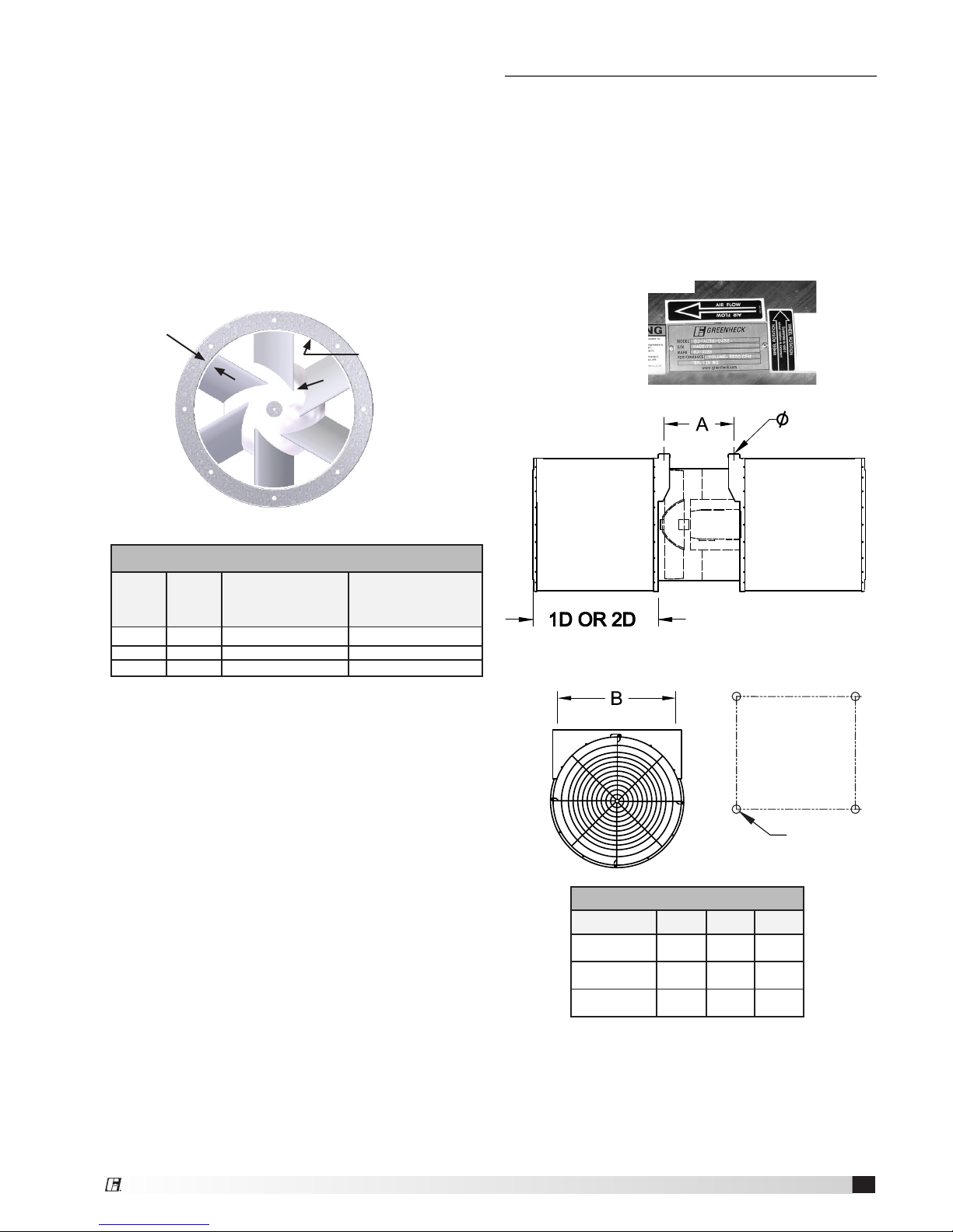
The examples shown below is installed using standard
mounting brackets. Before beginning installation,
reference the airow direction as indicated by the
direction decal attached to the fan.
REMOVING FROM STORAGE — As units are removed
from storage to be installed in their nal location, they
should be protected and maintained in a similar fashion,
until the equipment goes into operation.
Prior to installing the unit and system components,
inspect the unit assembly to make sure it is in working
order.
1. Check all fasteners on the fan, propeller, motor base,
and accessories for tightness.
2. Rotate the fan propeller by hand and assure no parts
are rubbing.
Prop Cut Diameter for Std and High Temp
Outer
Tube
Inner
Tube
Minimum Tip
Clearance for
Standard Temp Fan
Minimum Tip
Clearance for
High Temp Fan
315 225 1.0 3.5
355 225 1.0 3.5
400 225 1.0 3.5
Propeller
Clearance
Blade
Interior of tube
Hub
Airflow
Wheel
Rotation
Decals
This is the label
for a model
GJ-AU.
Ø
Mounting Pattern
Unit Size A B Ø
315-225 341 300 10
355-225 341 326 10
400-225 341 350 12
All dimensions are in millimeters.
Page 4
4
Jet Fan
Mounting
The fan should be mounted either rigidly or through
the use of vibration isolators. If vibration isolators
are used, consideration should be given to ensure
the safety of the installation. One method of ensuring
safety is through the use of a drop rod that would
‘catch’ the fan if the isolator were to fail during
normal operation or due to the excessive heat of a
fire.
Silencer Installation
The fan and silencers are shipped disassembled in
order to prevent freight damage. Required quantity
of bolts are provided for installation of silencer on
fan. Ensure that the silencer is centered on the fan
housing before tightening the bolts.
Unit Start-Up and Operation
Electrical Installation
Particular attention should be given when connecting
power to the unit. The power cable should be
installed to meet local requirements for high
temperature operation. The power cable should be
capable of meeting, as a minimum, the time and
temperature applications which the fan is capable of.
Before electrical connections are made, the supply
voltage, phase and ampere capacity must be
checked for compatibility with the fan motor. In
addition, the supply wiring must be properly fused
and conform to local and national electrical codes.
The supply wires are then connected to an optional
safety disconnect switch, to the optional wiring
pigtail, or directly to the motor junction box.
Pre-Start-Up Checks
1. Check all fasteners for tightness. Fasteners may
come loose during transit or handling at the jobsite.
This includes motor bolts, mounting brackets, and
bushing bolts attaching the propeller to the motor
shaft.
2. Ensure no debris, tools, or rubish is near the fan
inlet which might get pulled into the fan.
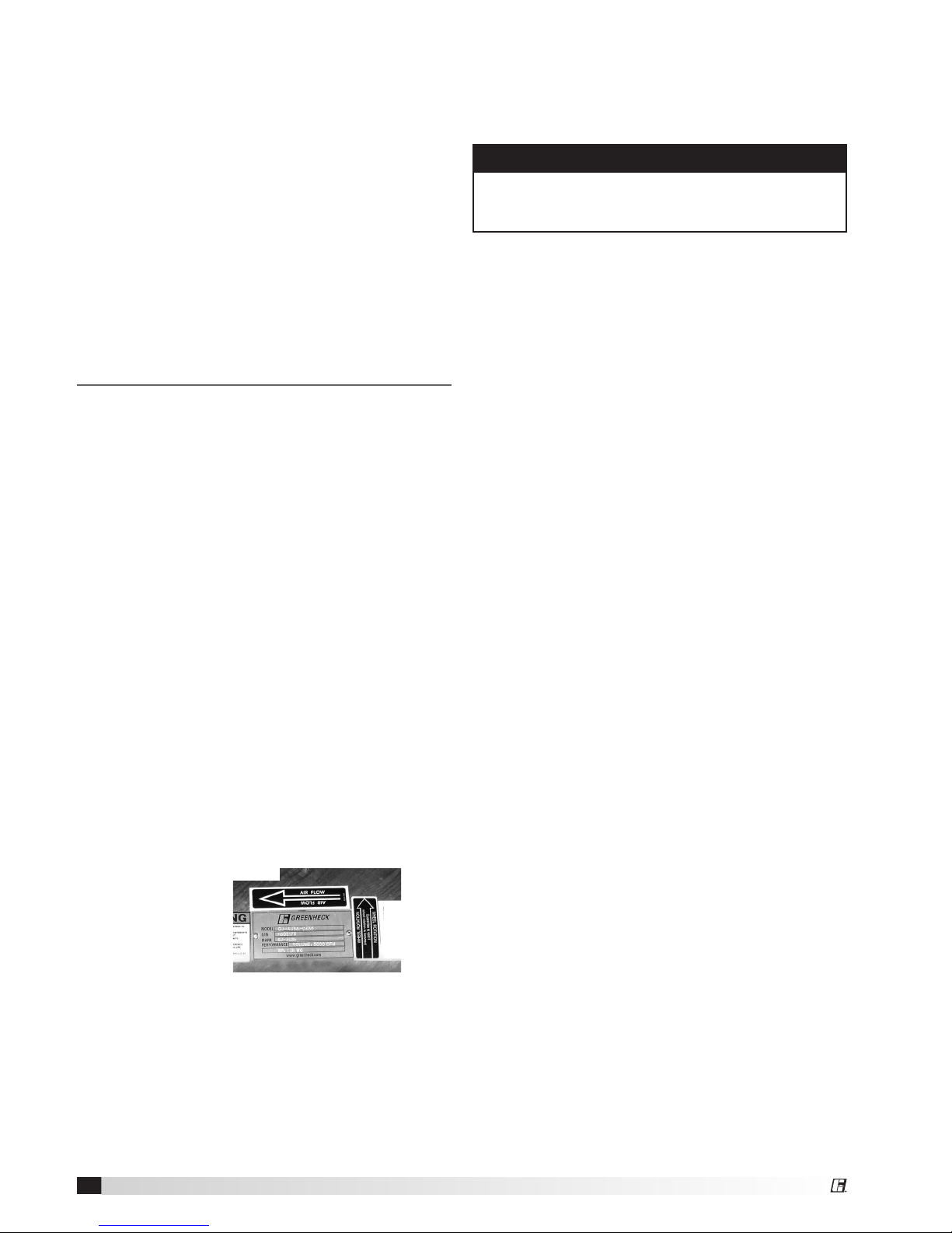
3. Propeller rotation
should be in the
same direction as
the rotation decal
afxed to the
unit. For 3-phase
installations, fan
rotation can be reversed by simply interchanging
any two of the three electrical leads.
4. Lead the power supply wires into the terminal box
on the outside of the fan.
5. Ensure the wiring conguration is connected as per
the wiring diagram on the motor.
6. Securely connect the motor ground wire and
building ground wire to the ground connection post
in the fan terminal box.
Adjusting Performance with a Variable
Frequency Drive
Before wiring a Variable Frequency Drive (VFD),
determine that the motor is compatible with this type
of equipment. Connecting a VFD to a non-compatible
motor may reduce the life of the motor. Additionally,
it is important to properly ground fans being wired
with a VFD. For more information on these subjects,
refer to Greenheck document “Are Bearing Currents
Causing Your Motor Failures?” located at www.
greenheck.com. Click on Application Info, then on
Product Application Articles, and use the keyword
“VFD”. Greenheck is not responsible for improper
wiring of a VFD or for potential motor damage as a
result of operating a fan over its maximum operating
frequency.
Field Performance Adjustments
The performance of a GJ fan can be adjusted
through the use of a Variable Frquency Drive (VFD) or
adjusting the fan pitch.
Check motor load amperage and compare to
nameplate rating when changing the fan speed or
blade pitch.
Airflow
Wheel
Rotation
NOTE
Any change—increase or decrease—in fan speed
(RPM) or blade pitch can represent a substantial
increase in power required from the motor.
Page 5
5
Jet Fan
WARNING
Disconnect and secure to the “Off” position all
electrical power to the fan prior to inspection
or servicing. Failure to comply with this safety
precaution could result in serious injury or death.
Maintenance
Once the unit has been put into operation, a
routine maintenance schedule should be set up to
accomplish the following:
1. Lubrication of the motor if required.
2. Propeller, housing and bolts on the entire fan
should be checked for tightness.
3. Any dirt accumulation on the propeller or in the
housing should be removed to prevent unbalance
and possible damage.
4. Inspection of fan propeller and housing looking for
fatigue, corrosion or wear.
Motors
Motor maintenance is generally limited to cleaning
and lubrication. Cleaning should be limited to
exterior surfaces only. Removing dust and grease
buildup on the motor housing assists proper motor
cooling. Never wash down the motor with high
pressure spray.
Many motors are permanently lubricated for life and
require no further lubrication.
Consult fan manufacturer for instructions on the
removal or replacement motors.
CAUTION
Do not allow water or solvents to enter the motor or
bearings. Under no circumstances should motors or
bearings be sprayed with steam, water or solvents.
Infrequent Use
Infrequent use is defined as a fan that is used
less than once per month or is used in emergency
situations only.
The fan should be run at least four hours every
month to ensure adequate lubrication in the motor
bearings. Ideally this would be two hours every other
week.
Fasteners and Set Screws
A periodic inspection should include checking all
fasteners and bolts for tightness. Particular attention
should be paid to the bushing attaching the propeller
to the motor shaft and the motor to its mounting
fixture.
Removal of Dust and Dirt
Dirt clogs the cooling openings on the motor
housing, contaminates bearing lubricant and collects
on the propeller causing severe imbalance if left
unchecked. The exterior surface of the motor and
propeller should be thoroughly cleaned periodically.
Use caution and do allow water or solvents to enter
the motor. Under no circumstances should motors be
sprayed with steam or water.
Page 6
6
Jet Fan
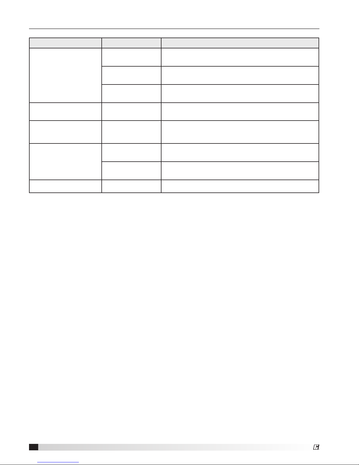
Troubleshooting
Problem Cause Corrective Action
Excessive Noise
Propeller Rubbing
Housing
Adjust motor plate. Tighten motor plate after centering
propeller in housing.
Bearings
Replace defective bearing(s). Lubricate bearings.
Tighten collars and fasteners.
Propeller Unbalance
Clean all dirt off propeller. Check propeller balance,
rebalance in-place if necessary.
Volume Too Low Fan
Check propeller for correct rotation.
Check blade pitch.
Excessive Power
Consumption High
Horsepower
Fan Check blade pitch.
Fan Doesn’t Operate
Electrical Supply
Check fuses/circuit breakers. Check for switches turned
off or disconnected. Check for correct supply voltage.
Motor
Assure motor is correct horsepower and not tripping
overload protector.
Bearings Overheated Lubrication Check for excessive or insufficient grease in the bearing.
Page 7

7
Jet Fan
Maintenance Log
Date _________________ Time______________ AM/PM
Notes: __________________________________________
________________________________________________
________________________________________________
________________________________________________
________________________________________________
Date _________________ Time______________ AM/PM
Notes: __________________________________________
________________________________________________
________________________________________________
________________________________________________
________________________________________________
Date _________________ Time______________ AM/PM
Notes: __________________________________________
________________________________________________
________________________________________________
________________________________________________
________________________________________________
Date _________________ Time______________ AM/PM
Notes: __________________________________________
________________________________________________
________________________________________________
________________________________________________
________________________________________________
Date _________________ Time______________ AM/PM
Notes: __________________________________________
________________________________________________
________________________________________________
________________________________________________
________________________________________________
Date _________________ Time______________ AM/PM
Notes: __________________________________________
________________________________________________
________________________________________________
________________________________________________
________________________________________________
Date _________________ Time______________ AM/PM
Notes: __________________________________________
________________________________________________
________________________________________________
________________________________________________
________________________________________________
Date _________________ Time______________ AM/PM
Notes: __________________________________________
________________________________________________
________________________________________________
________________________________________________
________________________________________________
Date _________________ Time______________ AM/PM
Notes: __________________________________________
________________________________________________
________________________________________________
________________________________________________
________________________________________________
Date _________________ Time______________ AM/PM
Notes: __________________________________________
________________________________________________
________________________________________________
________________________________________________
________________________________________________
Date _________________ Time______________ AM/PM
Notes: __________________________________________
________________________________________________
________________________________________________
________________________________________________
________________________________________________
Date _________________ Time______________ AM/PM
Notes: __________________________________________
________________________________________________
________________________________________________
________________________________________________
________________________________________________
Page 8

8
As a result of our commitment to continuous improvement, Greenheck reserves the right to change
specications without notice.
Specic Greenheck product warranties are located on greenheck.com within the product area tabs and in the
Library under Warranties.
®
[email protected] • www.greenheck.co.in
Our Commitment
480189 • GJ, Rev. 5, June 2018 Copyright 2018 © Greenheck Fan Corporation
 Loading...