

Page 1
1.97"
3.
1
5"
[
80]
3.
8
6" [
9
8]
2
.
2
4
"
[57]
[50]
1.93"
[
4
9]
2.64"
[67]
0.26" [6.5]
5.85" [148.5]
10.59" [269]
0.35" [9]
0.39" [10]
0.65" [16.5]
0.19" [5]
3
.
2
5
" [82.7]
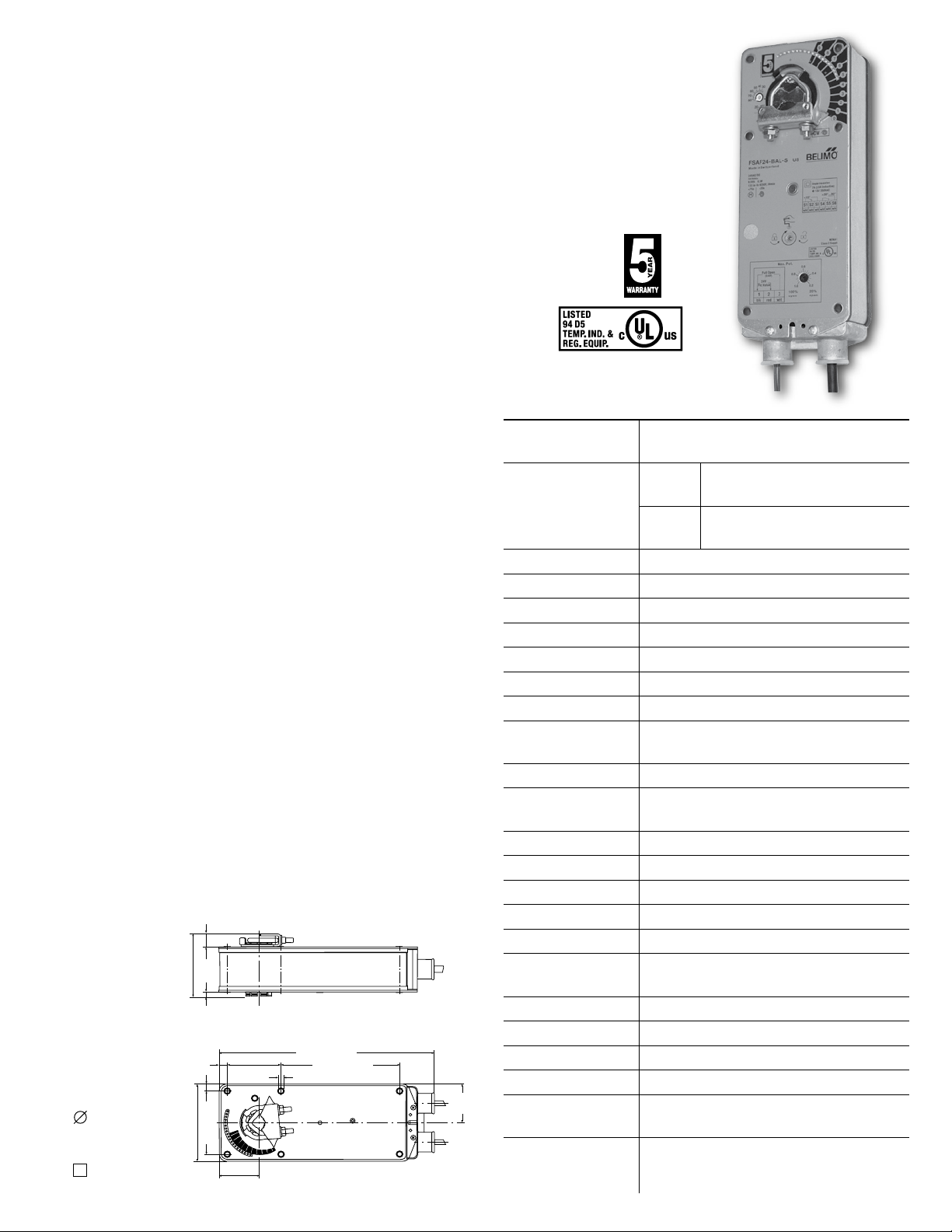
FSAF24-BAL (-S) US
70793-00001
Balancing Fire and Smoke Actuator, Three Position
Damper Actuator, Spring Return Closed, 24V, for
UL555(S) Fire and Smoke Dampers. A maximum
position potentiometer is built-in. 100% open override.
Application
For three position control of UL555S rated dampers in HVAC. Actuator
sizing should be done in accordance with the damper manufacturer’s
tests. In the absence of other information, use 10 in-lb of torque per
square foot of area for opposed blade and 14 in-lb for parallel blade fire
and smoke dampers at 1000 fpm air velocity.
The FSAF24-BAL is specifically designed to balance the air flow in ducts
and simultaneously provide control of fire and smoke dampers. 0V =
spring closed. 24V on wire 2, not 3 = drive to the potentiometer position
(balanced flow). 24V on wire 3, regardless of the status of wire 2 = drive
full open (smoke control extraction or pressurization). See Application
drawings below.
Operation
The FSAF24-BAL actuator provides spring return operation. There is no
reversing switch. Mount in spring return closed position. The torque
is asymmetrical giving 180 in-lb drive and 133 in-lb spring. A manual
override winder and locking mechanism is provided. If the manual winder
is used when the actuator is powered, the actuator will release, drive
closed, and then go back to the potentiometer position. The actuator may
not be mechanically parallelled or “piggybacked.” Each damper section
should be controlled by a separate actuator.
The FSAF24-BAL uses a DC motor which is controlled by a microchip.
The actuator may be stalled anywhere during its rotation without damage.
If power is removed, the damper will spring closed. Interlocks must be provided
as necessary for life safety functions and to shut down fan if required.
Dimensions (All numbers in brackets are metric.)
Standard
½” to 1.05”
Optional
½”
Technical Data FSAF24-BAL US
Power supply 24 VAC ± 20% 50/60 Hz
24 VDC ±10%
Power consumption running: AC 9.5 VA 6.5 W
DC 6 W
holding: AC 5 VA 3 W
DC 3 W
Transformer sizing 10 VA (Class 2 power source 24V only)
Electrical connection 3 ft, 18 ga, ½” conduit connectors
Overload protection electronic throughout 0 to 95° rotation
Control signal 24 VAC/DC 3-position
Angle of rotation 20° to 95°, pot adjustable
Torque 133 in-lb [15 Nm]
Direction of rotation reversible with CW/CCW mounting
Position indication visual indicator, 0° to 95°
(0° is spring return position)
Manual override 3mm hex crank (shipped w/actuator)
Running time motor: <75 seconds @ 250°F [121°C]
spring return: <20 seconds
Humidity 5 to 95% RH non-condensing
Ambient temperature -22°F to +122°F [-30°C to +50°C]
Storage temperature -40°F to +176°F [-40°C to +80°C]
Housing NEMA type 1 / IP40 (with flex conduit)
Housing material zinc coated metal
Agency listings cULus to UL 873 and CAN/CSA C22.2
No. 24-93
Noise level running: <45 dB(A), spring: <62 dB(A)
Holding inaudible
Servicing maintenance free
Quality standard ISO 9001, 5 year Belimo warranty
Weight 5.3 lbs (2.4kg)
5.7 lbs (2.6kg) for -S model
Auxiliary switch
2 x SPDT, 7A resistive, 2.5A inductive at
120/250 VAC, UL listed, double-insulated, one
switch is fixed at 10°, one is adjustable 30° to 90°
Page 2
Accessories (AF series accessories may be employed)
S1
S2
S3
S4
S5
S6
IND-AF2 Damper position indicator
K4-1 US Universal clamp for up to 1.05” dia. jackshafts
KH-AF Crankarm for up to ¾” round shaft (Series 2)
KH-AF-1 Crankarm for up to 1.05” jackshaft (Series 2)
KH-AFV V-bolt kit for KH-AF and KH-AF-1
Tool-01 10 mm wrench
ZDB-AF2 Angle of rotation limiter
ZG-100 Universal mounting bracket
ZG-101 Universal mounting bracket
ZG-103 Universal mounting bracket
ZG-104 Universal mounting bracket
ZG-106 Mounting bracket for Honeywell® Mod IV replace-
ment or new crankarm type installations
ZG-107 Mounting bracket for Honeywell® Mod III or
Johnson® Series 100 replacement or new crankarm
type installations
ZG-108 Mounting bracket for Barber Colman® MA 3../4..,
Honeywell® Mod III or IV or Johnson® Series 100
replacement or new crankarm type installations
ZG-AF Crankarm adaptor kit for AF/NF
ZG-AF108 Crankarm adaptor kit for AF/NF
ZS-100 Weather shield (metal)
ZS-150 Weather shield (polycarbonate)
ZS-300 NEMA 4X housing
22965-00001 12mm form fit square shaft adaptor
For an overview of how to apply the accessories, see Belimo Mechanical
Accessories and refer to the Belimo Mounting Methods Guide.
Safety Note
The actuator contains no
components which the user
can replace or repair.
FSAF24-BAL (-S) US Typical Specification
Where indicated on drawings, combination fire and smoke and balancing
dampers shall be controlled by Belimo FSAF24-BAL or equal actuators.
The actuators must be designed so that they may be used for either
clockwise or counter clockwise failsafe operation. Actuator shall open
damper in <75 seconds per UL555S and shall spring closed in under 20
seconds. Actuators shall have a 5-year warranty and be manufactured
under ISO9001 International Quality Control Standards.
Actuator shall have an adjustable Maximum Opening Potentiometer which
shall be used by the TAB contractor to adjust flow to that portion of the
system fed by the damper.
The actuator shall spring closed if either the smoke detector or alarm
system removes power from it. Actuator shall spring closed if the primary
temperature thermodisc opens due to high ambient of >165°F or as
otherwise indicted on drawings.
The actuator shall drive full open if either the smoke control system 100%
open override or Fire Fighters Smoke Control Station override is activated.
Damper shall spring closed again if the thermodisc of a combination fire
and smoke damper opens due to high temperature (typically 250°F).
NOTE: When using FSAF24-BAL (-S) actuators, only use
accessories listed on this page.
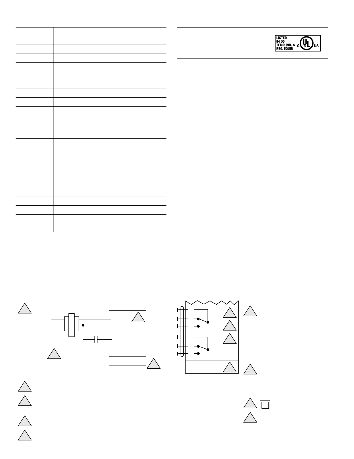
Wiring Diagrams Auxiliary switch wiring for FSAF24-BAL-S US
Line
Voltage
24 VAC Transformer
OVERRIDE CONTROL
See Wiring Diagrams
4
on following pages for
typical methods.
1 Blk Com
2 Red Hot
3 Override Open
FSAF24-BAL US
3
1
NC
10°
NO
NC
30° to 90°
NO
2
FSAF24-BAL-S US
1
3
2
4
For end position indication,
interlock control, fan start-up,
etc., FSAF24-BAL-S incorporates
two built-in auxiliary switches:
2 x SPDT, 7A resistive, 2.5A
inductive 120/250 VAC, UL
listed, one switch is fixed at 10°,
one is adjustable 30° to 90°.
2
Meets UL requirements without
1
the need of an electrical ground
1
Provide overload protection and disconnect as required.
2
Actuators may be connected in parallel. Power consumption
must be observed.
3
Actuator may also be powered by 24 VDC
4
Only connect Hot, Wire 2 to Wire 3 override control
2
connection. Actuator may also be
powered by 24 VDC
3
Double insulated.
4
Actuators may be connected
in parallel. Power consumption
must be observed.
Page 3

Wiring 1
Wiring 1 shows the basic operation of the FSAF24-BAL.
With 1 & 2 powered, actuator drives to
maximum potentiometer setting
Powering wire 3, regardless of
state of wire 2, drives actuator
full open.
Com24 VAC
Hot24 VAC
Close to override
full open
Maximum
Potentiometer
20% to 100%
1
2
3
FSAF24-BAL
Sequence of Operation for Wiring 1
If 1 & 2 are powered and 3 is not powered, actuator goes to Maximum
Potentiometer position. This is typically the balanced flow position.
If 1 & 3 are powered, regardless of the state of wire 2, the actuator goes
100% open. This is a purge mode.
Wiring 2
Wiring 2 shows one way to apply the FSAF24-BAL with a single thermodisc.
SMOKE DETECTOR
Hot24 VAC
SMOKE OVERRIDE
Hot24 VAC
1
2
3
100% OPEN
FSAF24-BAL
165°F
Com24 VAC
Sequence of Operation for Wiring 2
If 1 & 2 are powered, then actuator drives open to position as set by
potentiometer.
If smoke detector or other contact in wire 2 opens, then actuator springs
damper full closed.
If 1 & 3 are powered, regardless of state of wire 2, actuator drives
damper open 100%.
If 165°F thermodisc opens, actuator springs closed.
Manual reset required.
Wiring 3
Wiring 3 shows one method of wiring a Reopenable Damper using the
Fire Fighters override switch and two thermodiscs.
Dual Sensor Reopenable Damper
SMOKE DETECTOR
HOA Switch
Hot
24 VAC
FIRE FIGHTERS SMOKE
CONTROL STATION
165°F
A
O
H
250°F
COMBINATION FIRE SMOKE DAMPER
1
2
3
FSAF24-BAL
Com
24 VAC
Wiring 4
Wiring 4 shows an alternate wiring method to that shown in Wiring 3.
SMOKE DETECTOR
HOA Switch
Hot
24 VAC
FIRE FIGHTERS SMOKE
CONTROL STATION
165°F
A
O
H
FSAF24-BAL
250°F
1
2
3
Com
24 VAC
Sequence of Operation for Wiring 3 and Wiring 4
If HOA switch is in Auto position, smoke detector or other series contact
is closed and temperature is <165°F at thermodisc sensor, then actuator
wire 2 is powered and damper is driven open to adjustable position as set
by Maximum Potentiometer. If smoke detector or other contact in wire 2
opens or if the manual reset 165°F sensor opens, then actuator springs
damper closed.
If Hand-Off-Auto switch at FSCS is moved to Off, power to wire 2 is
removed and actuator springs damper closed.
If HOA switch is moved to the Hand position, power bypasses wire 2
and goes to wire 3. This reopens the damper for smoke evacuation or
pressurization control to the 100% open position.
If the 250°F thermodisc opens, the actuator springs closed and cannot be
overridden. Manual reset of each thermodisc is required.
WARNING: For UL555S Listed dampers and actuators,
follow damper manufacturer recommended field wiring
diagrams. Do not bypass high temperature limits.
3
Page 4

FSAF24-BAL (-S) US Balancing Fire and Smoke Actuator
Typical Applications
Most shafts carrying conditioned air from air handling equipment rooms
to multiple stories are installed in fire and smoke barriers. In addition, the
air to the floor must be balanced.
The FSAF24-BAL actuator allows one damper and actuator to do the job
that once required three dampers – a fire damper, a smoke damper, and
a balancing damper. See Figure 1.
From air handling unit
Wall is fire and smoke barrier. Duct
requires fire damper, smoke damper, and
the duct must be balanced for the space
air quantity requirement.
Wiring 3 and 4 show actuated damper wiring for Engineered Smoke
Control Systems. Where a smoke control damper is required in the wall
and a balancing damper is required for volume-temperature control, the
FSAF24-BAL provides a superior technical and economic solution.
See Figure 2. Other applications exist which are not covered here.
Fire Mode
Zone 1
Open 100% in fire Closed in fire
Shaft
To space
Smoke detector and
power wiring.
Figure 1
The two most common applications are dampers installed to contain
smoke and those installed in full engineered smoke control systems.
Wiring 2 on the preceding page shows the damper installed with a
smoke detector for containment. Figure 1 shows this application.
Closed in fire Open 100% in fire
Zone 2
Open 100% in fire Closed in fire
Zone 3
Figure 2
Non-dedicated smoke control system
The supply dampers are fire, smoke, and balancing. Three dampers in one.
Normally, the damper is balanced for the design supply air quantity. If a
fire occurs, the smoke zone supply damper closes and the adjacent zone
supply dampers open 100%.
The return dampers are not typically balanced and are normal fire and
smoke combination dampers.
In normal operating conditions, the BALANCING actuator is set to open
by the Maximum Potentiometer on the cover of the actuator. This is the
balancing position. It can be set as low as 20% open.
If the sensor detects ambient above 165°F (or as specified), the actuator
springs closed.
Belimo Air Controls • 203.791.9915 • www.belimo.com
If wired for smoke barrier protection or purge control, wire 3 may be
powered to open the damper actuator 100% to maximize the amount of
air to pressurize a space or remove smoke.
4
 Loading...