

Page 1
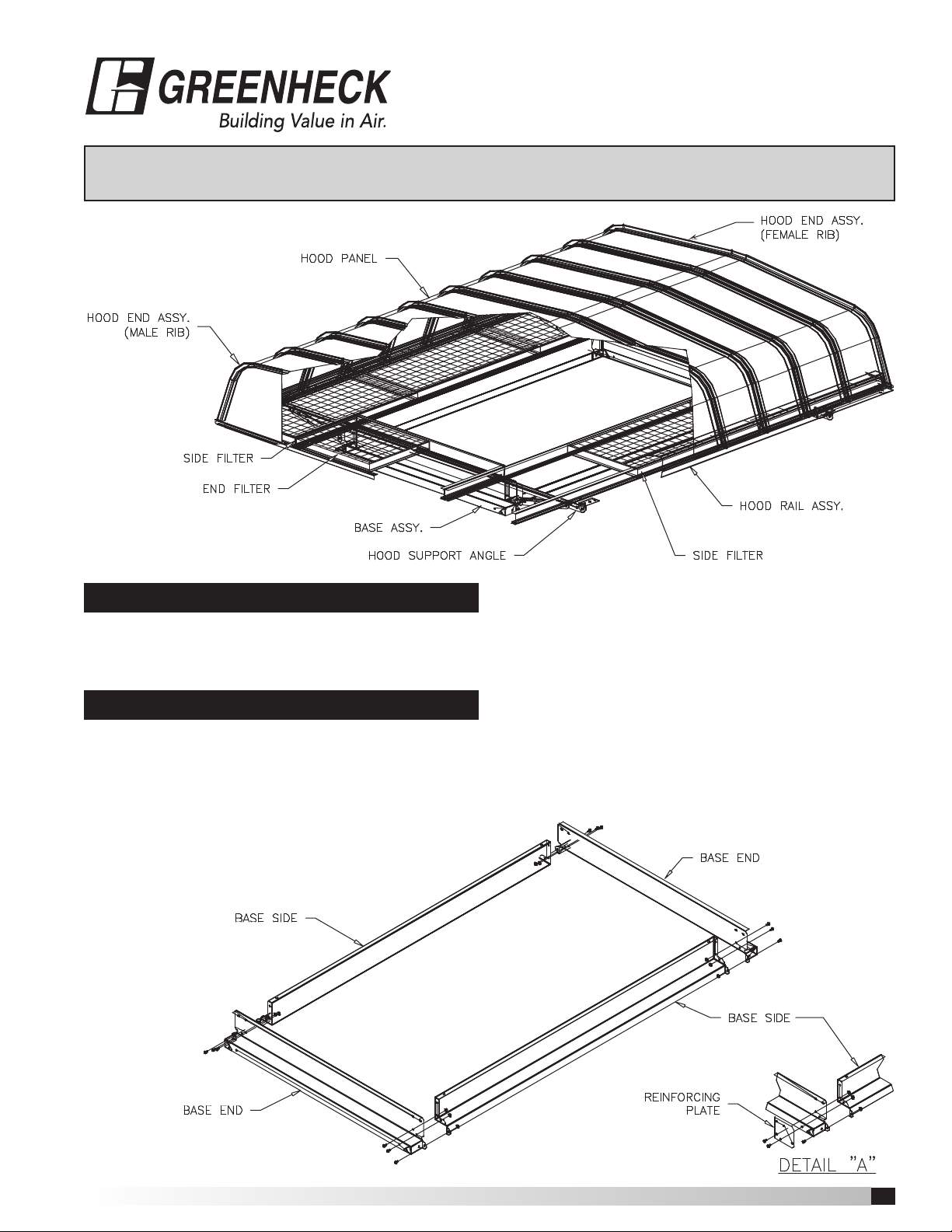
Figure 2 Fabra hood Form F 471322
Document #471322
Fabra Hood • Form F
®
Throat length less than or equal to 72 inches
Single Section with Filters
Assembly Instructions
Open the shipping crates and separate the parts
according to the size of the unit (See figure No. 1 on
attached "PARTS LIST")
Place the two BASE ENDS and the two BASE SIDES in
their approximate relationship to each other.
(See Figure 2) Fasten together using three (3) 1⁄4-20
fasteners per corner for 5 inch high base and four (4)
1
⁄4-20 fasteners per corner for 12 inch high base. Note:
Fasteners should be hand tightened only until step 4.
Figure 2
STEP 1
STEP 2
On some units where the difference between the
hood width and throat width is greater than 32 inches,
a REINFORCING PLATE is required in the corners of the
BASE (See Figure 2, DETAIL "A")
Fabra Hood • Form F
1
Page 2
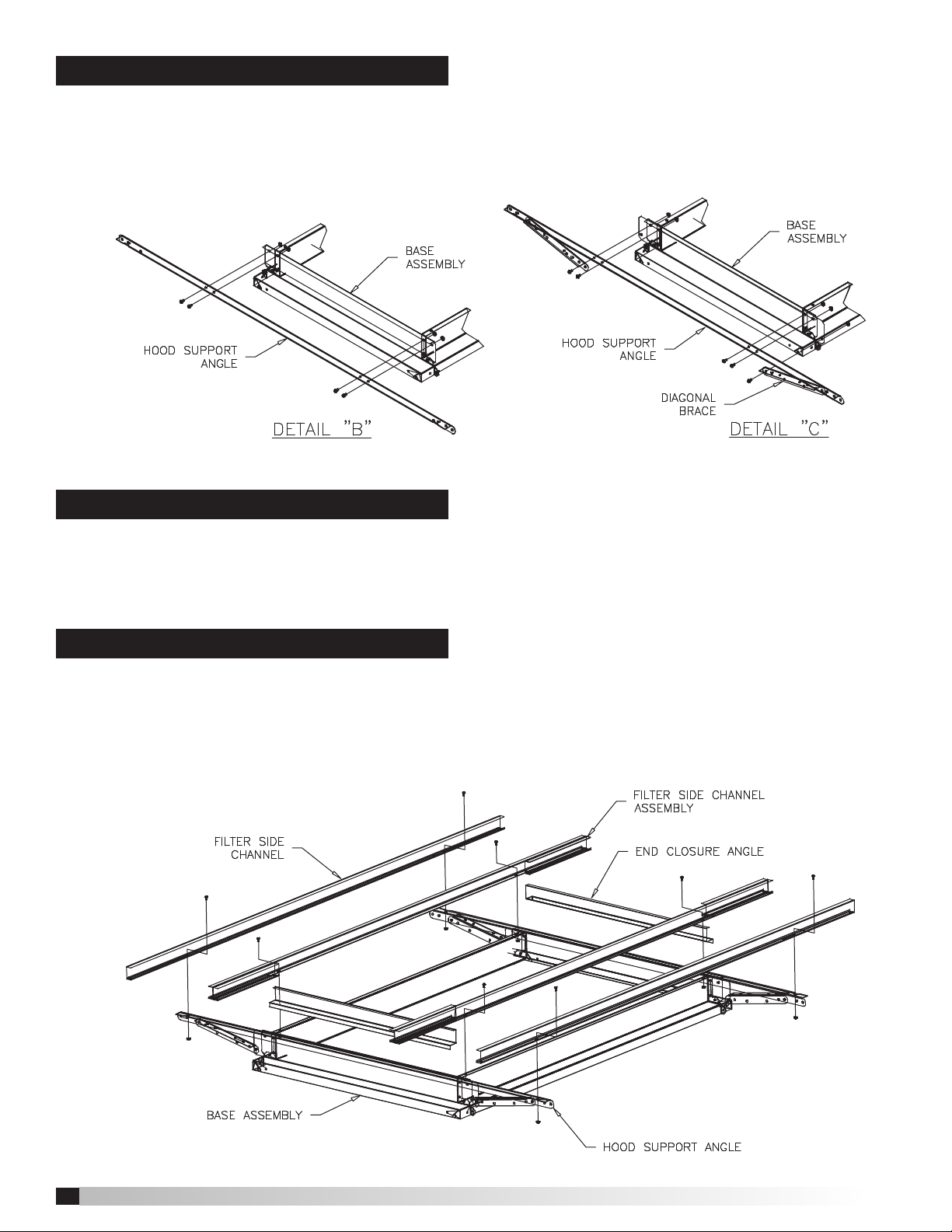
STEP 3
Attach the HOOD SUPPORT ANGLE to the BASE
ASSEMBLY, (hand tight) using four (4) 1⁄4-20 fasteners
per angle. (See Figure 3, DETAIL "B") On some units two
(2) DIAGONAL BRACES come pre-attached to
Figure 3
STEP 4
Tighten all BASE, SIDE and BASE END fasteners.
Caulk all inside corners where the base sections came
together. At this point, the base may be lifted onto the
roof curb before proceeding with further assembly.
the HOOD SUPPORT ANGLE. Fasten the loose end of
the DIAGONAL BRACES to the BASE ASSEMBLY using
one (1) 3⁄8-16 FASTENER PER diagonal brace. (See
Figure 3, DETAIL "C'')
STEP 5
Attach the FILTER SIDE CHANNEL (hand tight) to
the HOOD SUPPORT ANGLE and the FILTER SIDE
CHANNEL ASSEMBLY (hand tight) to the BASE SIDE,
using two (2) 5⁄16 X 1 inch weldstud fasteners per
Figure 4
channel. (See Figure 4) Sandwich the END CLOSURE
ANGLE between the BASE END and the SIDE FILTER
CHANNEL ASSEMBLY. (See Figure 4)
2
Fabra Hood • Form F
Page 3

STEP 6
Attach the END ANGLE (hand tight) to the ends of
the SIDE FILTER CHANNEL ASSEMBLIES and SIDE
CHANNELS using four (4) 5⁄16 X 1 weldstud fasteners per
END ANGLE. (See Figure 5) In addition, units with throat
widths greater than 36 inches will require
FILTER END CHANNEL ASSEMBLIES.
Figure 5
(See Figure 5, DETAIL ''D'') Fasten FILTER END
CHANNEL ASSEMBLY (hand tight) to the END
CLOSURE ANGLE and END ANGLE, using two
5
⁄16 X 1 weldstud fasteners per assembly.
STEP 7
Slide FILTERS in from both ends of unit. Tighten all
FILTER CHANNEL and END ANGLE fasteners only after
FILTERS are in place.
STEP 8
Attach the HOOD RAIL ASSEMBLY to the HOOD
SUPPORT ANGLES using two (2) 3⁄8 X 3⁄4 inch fasteners
per HOOD RAIL ASSEMBLY. (See Figure 6) NOTE:
Fasteners should be hand tightened only until step 9.
Figure 6
Fabra Hood • Form F
3
Page 4

STEP 9
Assemble HOOD PANELS to HOOD RAIL ASSEMBLY.
The HOOD END ASSEMBLY with the MALE RIB is to
be installed first. (See Figure 7, DETAIL "E") Place the
remaining HOOD PANELS in place, interlocking panels
as you go. (See DETAIL "E") Secure each HOOD PANEL
to the HOOD RAIL ASSEMBLY as it is put in place
using four (4) No. 12 X 3⁄8 inch sheet metal screws with
sealing washers per HOOD PANEL. The HOOD END
ASSEMBLY with the FEMALE RIB is to be installed last.
Figure 7
NOTE: Hoods over 9 feet wide are supplied with
special HOOD CLIPS. (See DETAIL "F'') HOOD
PANELS have predrilled holes for HOOD CLIP
installation. Install CLIPS as HOOD PANELS are being
put in place, using one (1) No. 12 X 5⁄8 inch sheet metal
screw with sealing washer per HOOD CLIP. To install
CLIPS in the last panel, remove the end FILTERS to
provide access to the underside of the hood. The
FILTERS can be easily replaced after the hood is
completely assembled.
STEP 10
Tighten all pivot bracket fasteners. NOTE: There may be extra fasteners.
®
Phone: (715) 359-6171 • Fax: (715) 355-2399 • E-mail: gfcinfo@greenheck.com • Website: www.greenheck.com
4
Fabra Hood Form F Assembly Instructions, Rev. 2, October 2012 Copyright © 2012 Greenheck Fan Corp.
 Loading...