

Page 1
1.0 bar
Standard setting
0.2 bar
0
0° 90°
Initial settings
Installation and
Operation
Pneumatic Positioner F10
CCW Direct
CW Reverse
Accredited by the
Dutch Council for
Certification
DOC.6.41.EI 10.98
Page 2

F 10 Pneumatic Positioner
Where to Find Information
Page
Product Description 1
Operating Principle 2
Installation, Rotary Actuators
- Mechanical 3
-Pneumatic, Double Acting 3
-Pneumatic, Single Acting 4
-Air Supply Requirement 4
Installation, Linear Actuators
-Mechanical installation 5
-Pneumatic installation 6
Calibration
-Initial Settings 7
-Cam Changes 7
-Zero Adjustment 8
-Range Adjustment 8
Trouble Shooting 9
General Specification:
Metric Imperial
Hysteresis : 0.6%
Linearity : 1.0%
Air Flow : 210 Nl/min (at 6 bar) : (7.4 SCFM at 87 psi)
Air Consumption : 15 Nl/min (at 6 bar) : (0.6 SCFM at 87 psi)
Min. volume
actuator : 0.1 Nl : 6.1 in
Temperature : -20° to +80° C : (-4° to +176°F)
Enclosure : IP54 (option IP65) : NEMA 3 (option NEMA 4)
Mounting : VDI/VDE 3845 or
IEC 534/6
Air Entry : G 1/4" : (1/4" NPT)
Air Supply : 1.4 to 8.6 bar : (21 to 125 psi).
Input Signal
- Standard : 0.2 to 1.0 bar : (3 to 15 psi).
- Adjustable : 0.2 to 0.6 bar : (3 to 9 psi).
: 0.6 to 1.0 bar : (9 to 15 psi).
3
Media : Non-lubricated instrument air, filtered at 25 micron.
: Dew point should be 10°C (18°F) below enviromental temperatur.
: Air quality class 3-2-3 accord. to ISO 8573-1.
Page 3
Product Description
The F10 positioner provides the means for a pneumatic actuator to be positioned to any point between
full open and full closed position. This allows accurate setting of rotary and linear control valves as
well as a wide range of dampers and similar devices. The actuator’s movement is controlled in
proportion to a 0.2 to 1 bar (3-15 psi) incoming
pressure signal.
The Posiflex F10 positioner provides:
-A single model covers both single acting and
double acting actuators.
- External Zero Adjustment.
- High accuracy due to “high gain” amplification.
-Four Position Cam for Linear Actuators
provides for linear, quick opening, equal percentage and split range characteristics.
- Three Position Cam for Rotary Actuators
provides for linear, quick opening and equal
percentage characteristics. A special cam for
rotary actuator provides for split range.
- Direct or Reverse Acting.
F 10 positioners are available for both rotary and
linear applications and because of the standardized mounting interface (VDI/VDE 3845 or IEC 534/
6), installation is simple and trouble free. Mounting
kits are available for most actuator types.
The purely Pneumatic mode of operation means
that F10 positioners may be used in explosion
hazardous areas without any additional protection
being necessary.
A wide range of modular control options are available: These cover the addition of gauges, indicating switches, position transmitters, etc.
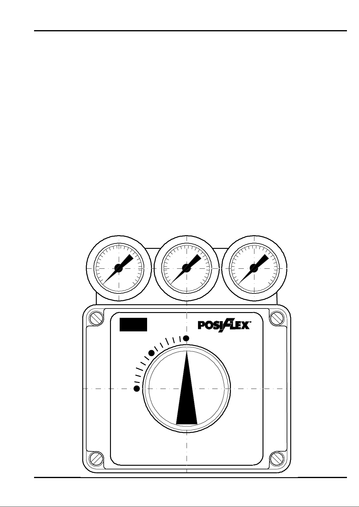
F10
Pneumatic
POSITIONER
Open
Closed
1.
Page 4
Operating Principles
The Posiflex F10 Pneumatic Positioner is a high
gain, motion balance instrument, suitable for use
with a wide variety of single acting and double
acting rotary and linear actuators.
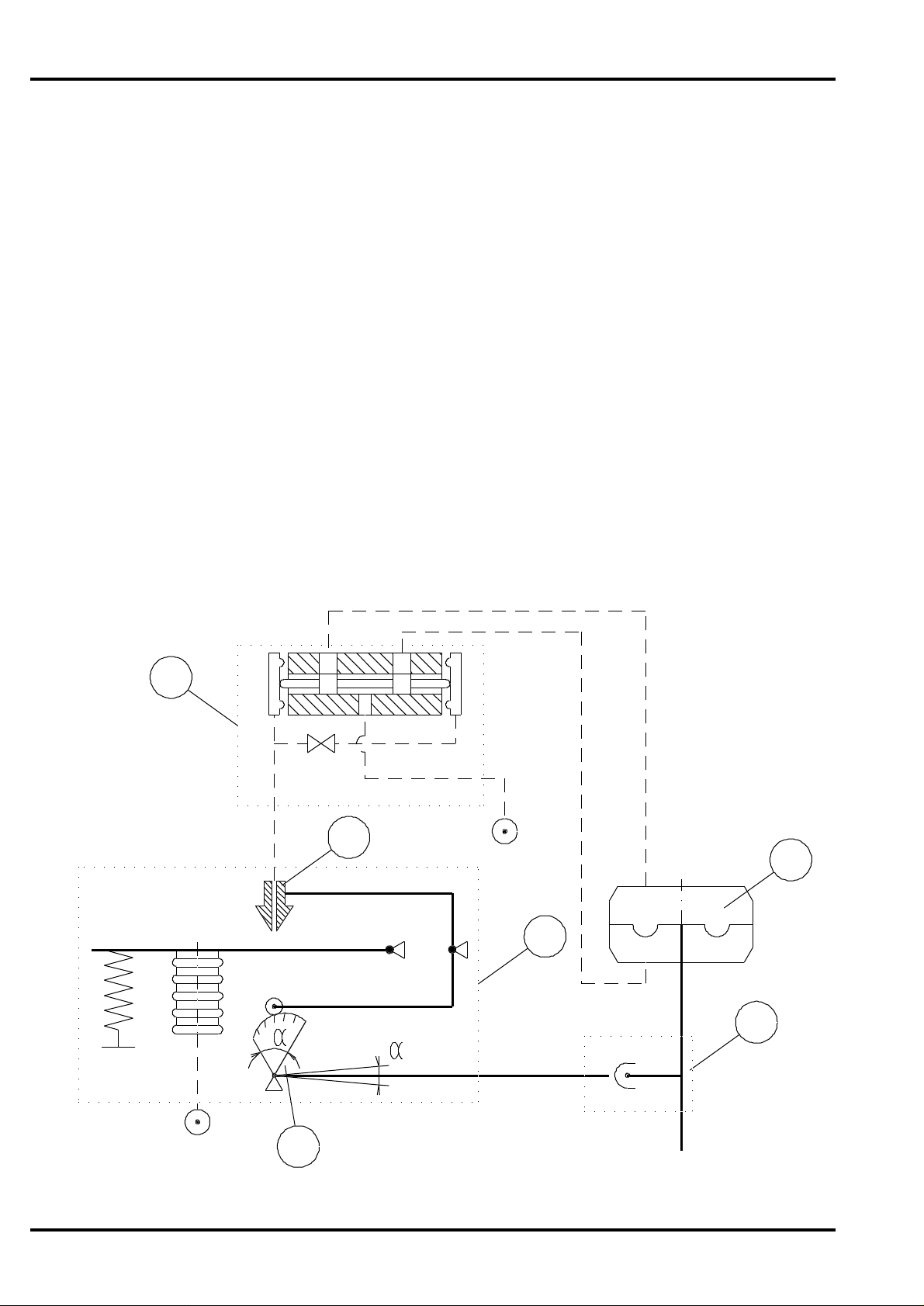
Referring to the diagram below: The positioner is
shown in a mid position with INSTRUMENT and
SUPPLY air connected. The flapper and nozzle (5)
maintains the instrument in it’s “balanced” state
with just enough pilot air pressure being applied to
the spool valve for it to hold the actuator in it’s “set”
position.
When the actuator is required to move to a new
“more open” position, the INSTRUMENT pressure
signal is increased accordingly. This closes the air
gap at the nozzle (5) causing an amplified pressure
1. Balance assembly.
2. Pneumatic valve block.
3. Actuator.
4. Mechanical feedback.
5. Flapper and nozzle.
6. Cam.
Output
increase at the spool valve end, this in turn displaces the spool and allowing an increasing air
pressure at the “open” side of the actuator and
exhausting air from the “close” side.
When the actuator moves position it rotates the
cam (6) in a CCW (counter clockwise) direction
and in doing so it progressively opens the air gap
at the nozzle (5). On reaching the new set point the
pilot pressure is reduced to the “balanced” state
and again locks the actuator in new set position.
Similarly a decreasing INSTRUMENT pressure will
cause a CW (clockwise) positioner movement.
The operation for single acting actuators is the
same except that the unused pneumatic connection
OUTPUT 2 is plugged off.
2
5
Supply
Close
3
1
Open
4
Instrument
6
2.
Page 5

Mechanical installation - Rotary actuators
The positioner is mounted on to the top surface of the
pneumatic actuator using an appropriate mounting kit.
The positioner’s mounting configuration is to the VDE/
VDI 3845 standard, if the actuator is to the same
standard, a standard NAMUR mounting kit can be
used, otherwise a special mounting kit will have to be
obtained.
Assuming the installation will use the standard NAMUR
mounting kit, proceed as follows:
1. Fix the bracket to the top surface of the actuator
using the 4 screws provided.
2. Check that the spring clip is securely in place on the
bottom of the positioner shaft.
3. Locate the positioner in place on top of the bracket,
making sure that the 4 mm. tongue locates properly
into it’s slot in the actuator spindle and the centring
screw is in position.
4. Fix the positioner to the bracket using the 4 screws
provided.
Installation Rotary Actuators
Mechanical Installation
Pneumatic Connections - Double acting
This assumes a standard (direct acting) installation
with an increasing signal to open the valve in a CCW
(counter clockwise) direction.
Before connecting any air supply make sure that
the air available is clean dry instrument air filtered
to at least 25 microns - see page 4.
1. Connect an appropriate piece of air tubing between
the port 1. on the positioner to the “A” port on the
actuator. (The “A” port is the one that when air is
applied to it, rotates the actuator in a counter clockwise direction).
2. Connect an appropriate piece of air tubing between
the port 2. on the positioner to the “B” port on the
actuator. (The “B” port is the one that when air is
applied to it, rotates the actuator in a clockwise
direction).
3. Connect an air supply to the positioner port Marked
“Supply”.
4. If the positioner is required to meet enclosure rating
IP54, be sure that the "Exhaust" port is connected
with elements which prevent the input of water and
give no pressure rising inside the housing because
of throttling of exhaust flow (no sintered filters, but a
piece of tube or a special IP65 Exhaust plug with
diaphragm
Supply
Instrument
Exhaust
1
A
2
B
Pneumatic connections
Double acting
5. Connect the instrument air to the port marked
"INSTR".
Note: For a reverse acting assembly, both the air
connections and the cam plate must be
reversed - see page 7.
3.
Page 6

Installation Rotary Actuators
Pneumatic Connections - Single acting
This assumes a standard installation, direct acting
with an increasing signal to open the valve in a
CCW (counterclockwise) direction.
Before connecting any air supply make sure
that the air available is clean dry instrument air
filtered to at least 25 microns - see below.
1. Connect an appropriate piece of air tubing
between the port 1. on the positioner to the “A”
port on the actuator. (The “A” port is the one
that, when air is applied to it, rotates the actuator in a counter clockwise direction).
2. Connect an air supply to the positioner port
marked “Supply”.
3. The unused positioner port 2, should be
plugged using the pipe plug supplied with your
positioner.
Connect port "Exhaust" with elements, which
guarantee IP54.
4. If the positioner is required to meet enclosure
rating IP54, be sure that the "Exhaust" port is
connected with elements which prevent the
input of water and give no pressure rising inside
the housing because of throttling of exhaust flow
(no sintered filters, but a piece of tube or a
special IP65 Exhaust plug with diaphragm.
5. Connect the instrument air to the port marked
"INSTR".
Supply
Exhaust
1
A
Instrument
2
Pneumatic Connections
Single acting
Note: For a reverse acting assembly, use the
same procedure but remember that a reverse acting actuator must be used - see
page 7.
Air Supply Requirements
CAUTION: Pressure in excess of 8.6 bar (125 psi)
will cause damage to the Positioner.
Positioner supply air must be clean, dry
and oil free.
The air should be filtered to at least 25 microns
(as defined in the Instrument Society of America
standard ISA S7.3 specifications). The filter should
be installed as close to the positioner as possible
to ensure maximum efficiency.
4.
Page 7

Mechanical Installation - Linear Actuators
The mountings for linear positioners will vary dependent
on the type of control valve.
The simplest assembly is where the control valve yoke is
to the standard IEC 534-6 and has type “C” (Pillar) yoke
design. A standard mounting kit is available for this and
will provide a suitable mounting for most valves in this
category.
Installation - Linear Actuators
7
6
3
Typical installation for a direct acting assembly. (Increasing signal opens the valve with a rising spindle).
1. Fix the bracket (1) to the positioner base, using the four
bolts provided.
2. Move the valve spindle into a mid-stroke position.
3. Fix the lever (2) to the valve connection block (3) using
the two M6 bolts. The carrier bolt (5) should be positioned loosely in the lever (2).
4. Assemble the slider on the feed back lever (7). Use
assembly "a" (below) for strokes 60 to 100 mm. or
assembly "b" for strokes 10 to 40 mm.
5. Locate the positioner, together with the bracket (1) on
the left-hand pillar using the "U"-bolt clamps (4). (Use
the right-hand pillar for reversacting assemblies). pass
the carrier bolt (5) through the feedback lever slot,
taking care to keep the anti-backlash spring (6) in it's
correct position.
2
4
1
5
Linear mounting
Slider installation for 100 mm. stroke
6. Slide the positioner up or down the pillar until the lever
(2) and the feedback lever (7) are parallel. Fix in position.
7. Adjust the linkage to the correct stroke by moving the
slider until the appropriate position on the feedback
lever is indicated. Then tighten the carrier bolt (5).
8. Let the actuator make a full stroke and check that the
linkage moves freely within the bracket.
9. Move the actuator to it's "zero" position. Turn the
positioner shaft counterclockwise (CCW) to the end of
stroke. Fasten the feedback lever to the positioner
shaft.
5.
Installation mark for 60 and 100 mm. stroke
a) Lever for 60 to 100 mm. Stroke
Installation mark for 10 and 16 mm. stroke
Installation mark for 20 and 40 mm. stroke
Slider installation for 25 mm. stroke
b) Lever for 10 to 40 mm. Stroke
Page 8

Installation - Linear Actuators
Pneumatic Connections - Double acting
Assuming a standard installation, direct acting with an
increasing signal to open the valve (rising spindle).
Before connecting any air supply make sure that
the air available is clean dry instrument air filtered
to at least 25 microns.
1. Connect an appropriate piece of air tubing between
the port 1. on the positioner to the “A” port on the
actuator. (The “A” port is the one that, when air is
applied to it, opens the valve).
2. Connect an appropriate piece of air tubing between
the port 2. on the positioner to the “B” port on the
actuator. (The “B” port is the one that when air is
applied to it, closes the valve).
3. Connect an air supply to the positioner port marked
“S”.
4. If the positioner is required to meet enclosure rating
IP54, be sure that the "Exhaust" port is connected
with elements which prevent the input of water and
give no pressure rising inside the housing because
of throttling of exhaust flow (no sintered filters, but a
piece of tube or a special IP65 Exhaust plug with
diaphragm
5. Connect port "Instrument" with pneumatic input
signal.
Double acting
Note: For a reverse acting assembly, both the air
connections and the cam must be reversed see page 7.
Pneumatic Connections - Single acting
Assuming a standard installation, with direct acting an
increasing signal to open the valve (rising spindle).
Before connecting any air supply make sure that
the air available is clean dry instrument air filtered
to at least 25 microns.
1. Connect an appropriate piece of air tubing between
the port 1. on the positioner to the “A” port on the
actuator. (The “A” port is the one that when air is
applied to it, opens the valve).
2. Connect an air supply to the positioner port marked
“S”.
3. If the positioner is required to meet enclosure rating
IP54, be sure that the "Exhaust" port is connected
with elements which prevent the input of water and
give no pressure rising inside the housing because
of throttling of exhaust flow (no sintered filters, but a
piece of tube or a special IP65 Exhaust plug with
diaphragm
Single acting
4. Connect port "Instrument" with pneumatic input
signal.
Note: For a reverse acting assembly, both the air
connections and the cam must be reversed see page 7.
6.
Page 9

Initial Settings
Cam Segment
Rotary actuator
Linear actuator
40° CCW
40° CW
lin
=%
QO
SR
Calibration - Initial Settings - Cam Changes
The factory settings provide the positioner with an initial
range of settings that will allow the operation of positioners on most applications.
Signal Input - 0.2 to 1.0. bar. (3-15 psi).
Range - 0% to 100%
Control Function - Linear.
Action - Direct Acting.
(Opening on increasing Signal in
CCW-direction).
The F10 positioner is provided with the following features
for making changes to the initial settings:
Zero By the external zero adjustment screw.
Range By the internal range adjustment ring.
Range Spring The standard range spring is suitable for
normal operation and split ranging.
Cam Segment Six segments are provided for the rotary
positioner and eight segments for the
linear positioner (see table).
Cam Changes
Remove the cover and indicator from the positioner
exposing the Cam. The Cam is double sided: CCW for
direct acting, CW for reverse acting.
If the actuator is fully clockwise and the actuator is to
rotate CCW on instrument signal increase, the Cam
should be on the “CCW” side and the start marking
should be in line with the Cam Follower Bearing. If the
actuator is fully counterclockwise and the actuator is to
rotate CW on instrument signal increase, the Cam should
be on the “CW” side and the start marking should be in
line with the Cam Follower Bearing.
If the cam is not in the correct position, change as follows:
1.0 bar
0.2 bar
0
Standard setting
CCW Direct
CW Reverse
0°
Initial settings
90° CCW 90° CW
lin lin lin
=% =% =%
QO QO QO
* * SR
lin = linear
=% = equal percentage
QO = Quick Opening
SR = Split Range
* = Special cam split range
90°
2
1
1. Remove the cam nut (1).
2. Re-install the cam plate in the correct position, taking
3. Replace the cam nut and fix it.
4. Replace the indicator disk, taking care that it in the
care that the correct segment is adjacent to the cam
follower (2).
correct position.
7.
Top view of cam
Rotary actuator
Cam 90°
Linear actuator
Cam 40° (49°)
Page 10

Calibration - Zero and Range
Before making any adjustments positioner should
be properly mounted, the cam should be in the
correct sector on the correct side as determined
from the cam markings.
Zero Adjustment
The zero adjustment is carried out externally, this is
located at the right hand side of the positioner
casing and is accessed by means of a removable
plug.
1. Remove the access plug (1).
2. Adjust the instrument signal to its minimum value
(0.2 bar for a 0.2-1.0 bar range),
(3 psi for a 3-15 psi range).
3. Rotate the Zero adjusting screw (2) until the
actuator just begins to move. Turning the adjusting nut clockwise raises the start value.
4. After adjustment, replace the access plug (1).
Range Adjustment
Remove the cover from the positioner exposing the
knurled range adjuster ring, this is located at the
righthand side of the assembly.
The factory set range is so that a 0.2 to 1.0 bar (315 psi) instrument pressure produces a full stroke
movement. This may be changed by resetting the
full stroke position (max. opening) at the 1.0 bar
(max. instrument) pressure. To adjust the range
carry out the following:
1. Increase the instrument signal to its maximum
value (1.0 bar for a 0.2 to 1.0 bar range), (15 psi
for a 3-15 psi range).
2. If the actuator does not reach its final position,
rotate the knurled adjusting ring (3) in CCWdirection until the full stroke position is reached.
3. Turning the range screw cw reduces the range;
ccw increases the range.
4. After range adjustment, reset the zero position
and adjust it if necessary.
3
2
1
8.
Page 11

Troubleshooting
If it is suspected that the positioner is not operating correctly, check
the following :
1. Is the Cam in the proper orientation for your
application ? (See page 5).
2 Is the positioner properly mounted ? (See page
3).
3. Is the coupling or NAMUR shaft in proper
alignment with the Positioner Cam shaft and
actuator ?
4. Is the positioner piped correctly ? (See page 3
and 4).
5. Make sure supply pressure exceeds minimum
pressure required to move the actuator.
6. Is there instrument and output pressure at the
Positioner ? (If the Positioner is equipped with
a Gauge Block, check the instrument and
output pressure readings. If the positioner is
not equipped with a Gauge Block, connect
gauges to the instrument and output ports and
note readings.)
7. Is the actuator working properly ? (Disconnect
the supply pressure from the Positioner and
connect the supply pressure to the actuator.
Does the actuator move full stroke ?)
Maintenance
If additional help is needed, contact your local Elo-matic office or representative, (see back page).
9.
Page 12

INTERNATIONAL BENELUX UNITED KINGDOM
EL-O- MATI C B.V. EL-O- MATI C Benelux EL-O- MATIC Ltd.
P. O . Bo x 223 P. O . Bo x 223 16/1 7 Beedi ng Cl ose
7550 AE Hengelo (O) 7550 AE Hengelo (O) Southern Cross Trading Estate
Asvel dweg 19 Asvel dweg 11 Bognor Regis
7556 BR Hengelo (O) 7556 BT Hengelo (O) West Sussex, PO 22 9TS
Holland Holland Tel. +44 1243 830 3 63
Tel. +31 74 256 10 10 Tel. +31 74 256 10 20 Fax. +44 1243 830 843
Fax. +31 74 291 09 38 Fax. +31 74 243 86 90
FRANCE GERMANY U.S.A.
EL-O- MATI C France EL -O- MATI C GmbH. EL-O- MATIC U.S.A. Inc.
Z.A. Créapole 1 Postfach 460234 . 47856 Willich 1 35 Engl ish Street
32 R ue de Tour nenfi ls Si eme nsr ing 112 . 4 7877 W i ll ich Hackensack NJ 0 7601
91540 Mennecy Tel. +49 2154 499660 Tel. +1 201 489 5550
Tel. +33 1 69 900 734 Fax. +49 2154 427669 Fax. +1 201 489 9171
Fax. +3 3 1 69 900 709
VENEZUELA INDIA SINGAPORE
EL-O- MATI C INTERNAT IO NAL EL-O- MATIC I ndia Pv t Ltd. EL-O -MATIC Valve Actuators
Av. Princ ipal Los Ruices 296 /A/1/5, St. Patrick ’s T own Fa r East Pte L td.
Edif. stemo piso 1 Ofc. 1A Near Railway Crossing 28 Third Lok Yang Road
Caracas Had apsar In dustrial Estate Si ngapor e 628016
Venezuela Pune 411 013 Tel. +65 26 24 515
Tel. +58 2 237 77 51 Tel. +91 212 672916 Fax. +65 2680028 / 770 80 80
Fax. +5 8 2 238 9023 Fax. +9 1 212 674465
SOUTH AFRICA AUSTRALIA / NEW ZEALAND
EL-O-MATI C (Pty) Ltd. EL-O-MATIC Austral-Asia
Teknipark, 62 Lower Germiston Road 329 Brighton Road, Brighton 5048
Heriotd ale, Jo hannesburg P. O . Bo x 12
P.O. Box 40348 Glenelg 5045
Cleveland 2022 South Australia
Tel. +27 11 626 2880/1/2 Tel. +61 8 377 2744
Fax. +2 7 11 626 2905 Fax. +6 1 8 377 2576
 Loading...