

Page 1
Part #474047
®
®
Supplementary Information
This unit is equipped with a Model PVF Indirect GasFired furnace that has a 4:1 turndown. The primary
gas control valve used in this unit is a Honeywell
combination valve. It controls the high fire gas supply
and acts as an on/off switch. The EXA valve is located
just after the Honeywell combination valve and the
EXA valve is the device that modulates or changes
the gas volume that is being supplied to the furnace
manifold. These valves require adjustment at time
of unit start-up.
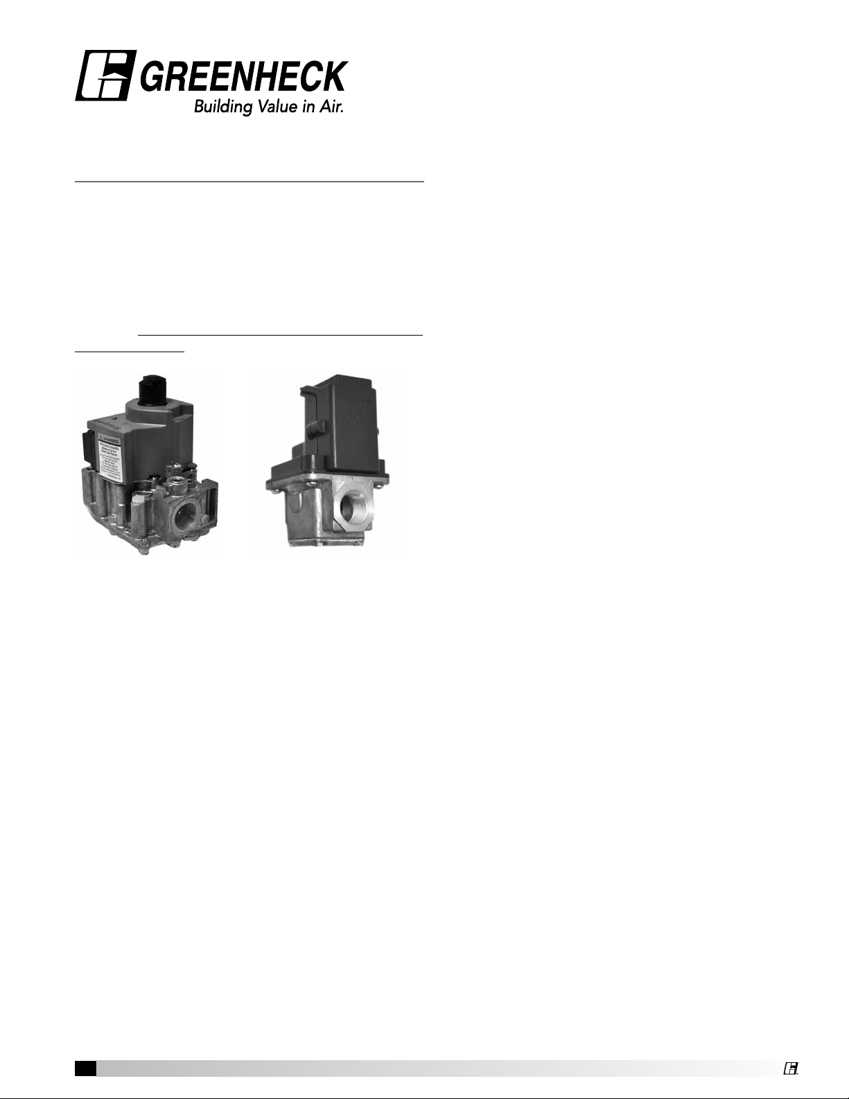
Typical Honeywell
Combination Valve
The EXA gas valve has a built-in digital controller that
will accept user settings for High Fire and Low Fire
and will provide minimal hysteresis throughout the
entire range of modulation. The EXA valve controls the
amount of combustion gas that goes to the burner,
rather than just a simple on/off. During normal use,
the amount of combustion gas will vary constantly,
depending on the settings put in by the owner. This
allows the EXA valve to regulate the heat output
from the furnace and maintain a constant space
temperature with minimal variation, or hysteresis.
The EXA Modulating Valve is controlled by a user
interface known as the FX05 Controller, made by
Johnson Controls. The FX05 Controller sends an
analog signal to the EXA modulating valve that causes
the valve to send more or less gas to the furnace.
Typical EXA
Modulating Gas Valve
Furnace Model PVF
4:1 Modulating Valve
Both the Honeywell and the Maxitrol gas valves
have been set at the factory for ideal operating gas
pressures. Vibration during shipment of the unit and
field conditions require that both valves be readjusted
at the time of start-up. At start-up,
• Set the High Fire set point on the EXA valve by
opening it all the way.
• Set the High Fire set point on the Honeywell valve
to 3.5 inch WC for natural gas or 10.0 inch WC for
LP gas.
• Set the Low Fire set point on the EXA gas valve
at 0.3 inch WC for natural gas or 1.0 inch WC for
LP gas.
The Maxitrol EXA valve has four electrical connections
on board. Two are for the 24 VAC needed to power
the valve and the circuit board and two are for the
input signal from the FX05. The location of the 24VAC
power source varies, see the unit-specific wiring
diagram. The input signal that causes the EXA valve
to change gas volume is always provided by the FX05
Controller and varies from 2 – 10 VDC.
When a call for heat is provided to the FX05 Controller,
the controller will provide a 10 VDC signal to the EXA
valve so that it will always start in a high fire condition.
After ignition, the controller will change its output
signal, causing the volume of combustion gas to be
reduced to as little as 25% of full flow (4:1 turndown).
For every installation of this indirect gas-fired furnace,
it is necessary to set the High Fire and the Low Fire
settings on the EXA valve. This is a simple process
that must be done in the field after the rest of the unit
is operational. To enter the High Fire and Low Fire
settings, it is necessary to have access to the EXA
valve on-board printed circuit board and to be able to
observe the LED on the printed circuit board.
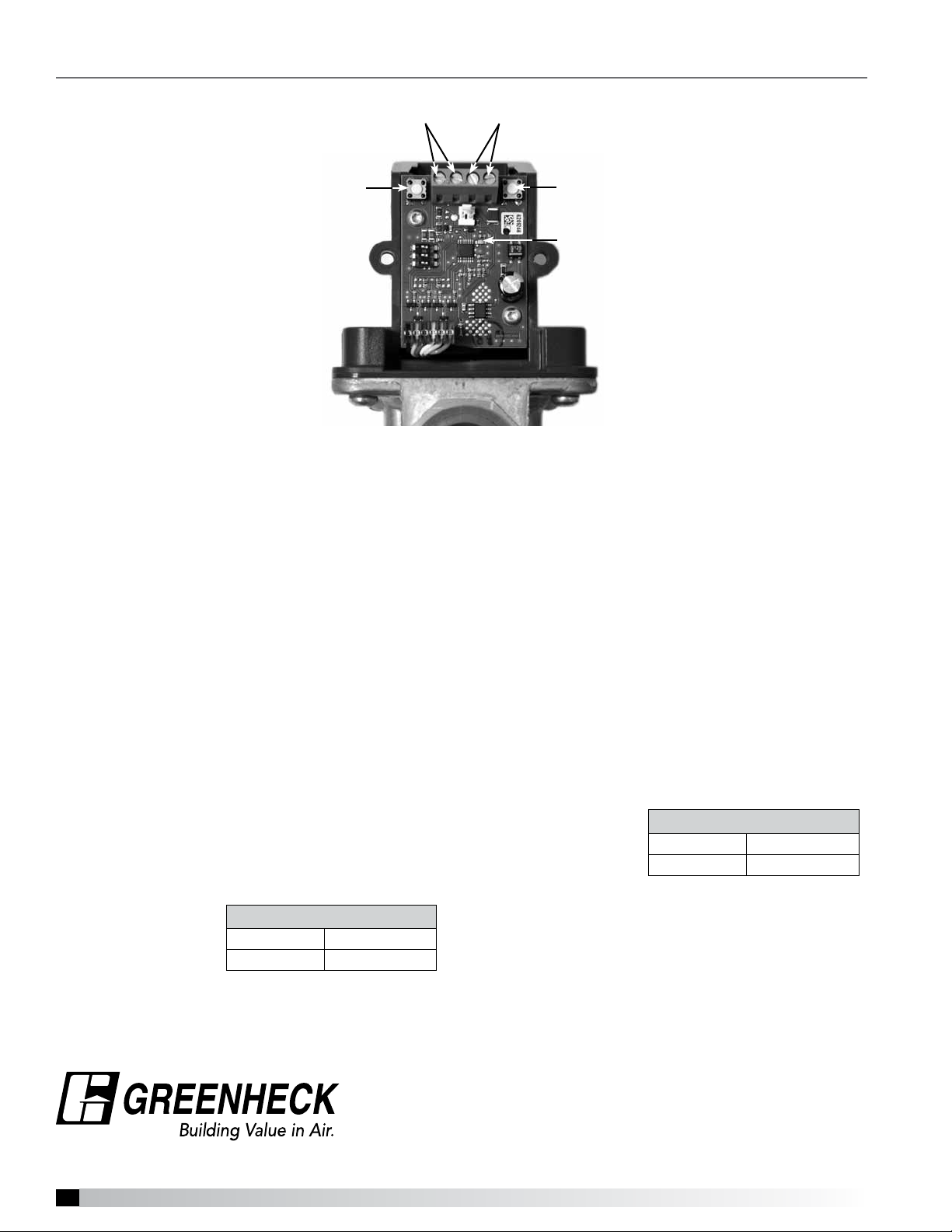
Remove the cover from the circuit board housing
by loosening the two Phillips head retaining screws.
Identify Button #1 and Button #2 and also locate the
LED indicator light.
4:1 Modulating Valve
1
Page 2
Adjust High and Low Fire Settings
Terminals 1 & 2
(signal)
Button #1
EXA Modulating Gas Valve
(with cover removed)
EXA Valve High Fire Setting / Button #1
Buttons #1 and #2 are used to set desired high fire
setting. To enter the High Fire setting mode, press and
hold button #1 until the LED lights solid red. Release.
The valve is now in the high fire setting mode.
Terminals 3 & 4
(power)
Button #2
LED Light
EXA Valve Low Fire Setting / Button #2
To enter into the low fire setting mode, press and hold
button #2 until the LED light blinks red. Release. The
valve is now in the low fire setting mode. Buttons #1
and #2 are used to set the desired low fire setting.
Press or hold button #1 to increase gas flow. Each
press of the button is equal to the minimum available
step size and will increase gas flow slowly. Holding
the button down auto steps and eliminates the need
to repeatedly press the button. Use this feature to
rapidly increase the gas flow to the maximum setting
available.
To save the High Fire setting, simultaneously hold
buttons #1 and #2 until the LED turns off.
NOTE: Controls left in the High Fire setting mode will
default to the current setting after five (5) minutes of
inactivity.
After adjusting the High Fire setting on the EXA
Modulating Valve, then adjust the High Fire setting
on the Honeywell
combination valve
as described in the
furnace IOM.
High Fire Settings
Natural Gas 3.5 inches WC
LP Gas 10.0 inches WC
Press or hold button #2 to decrease gas flow. Each
press of the button is equal to the minimum available
step size and will decrease gas flow slowly. Holding
the button down auto steps and eliminates the need
to repeatedly press the button. Use this feature to
rapidly decrease the gas flow.
Press or hold button #1 to increase gas flow. Each
press of the button is equal to the minimum available
step size and will increase gas flow slowly. Holding
the button down auto steps and eliminates the need
to repeatedly press
the button. Use this
feature to rapidly
increase the gas flow.
Low Fire Settings
Natural Gas 0.30 inches WC
LP Gas 1.0 inches WC
To save the Low Fire setting, simultaneously hold
buttons #1 and #2 until the LED turns off.
NOTE: Controls left in the Low Fire setting mode
will default to the current settings after 5 minutes of
inactivity.
Follow the instructions in the PVF Furnace IOM and
unit IOM to complete the rest of the startup
®
Phone: (715) 359-6171 • Fax: (715) 355-2399 • E-mail: gfcinfo@greenheck.com • Website: www.greenheck.com
474047 • 4:1 Modulating Valve, Rev. 1, August 2010 Copyright 2010 © Greenheck Fan Corporation
2
 Loading...