

Page 1

BUILDING VALUE IN AIR.
October
2005
Recirculating Roof Fans
Models ESRMD, ESRMDF and ERD
Four-Way Fan
• Exhaust
• Supply
• Mix
• Recirculate
Page 2

2
Recirculating Roof Fans
Exhaust/Supply/Recirculation/Mix
Model ESRMD
Ventilation requirements are often subject to daily or seasonal changes in temperature. The
Greenheck Four-Way Fan offers the flexibility to meet changing needs and to maintain
comfortable temperatures in factories, warehouses and other facilities with high ceilings. When
temperatures change with production processes or seasonal shifts, the Four-Way fan can
exhaust, supply, recirculate or mix air as required.
• Model ESRMD fans are available in six direct drive sizes.
• Performance capacities range from 4,000 cfm to 40,000 cfm and up to 0.375 in. wg of static
pressure.
• Exhaust, supply and recirculate modes perform equally.
Cost Savings
By exhausting excess heat, supplying cool air, recirculating stratified warm air, and mixing supply air with recirculated air,
the Four-Way fan also saves heating and cooling costs. When one fan offers four functions, further cost reductions result.
Fewer fans required on the job means lower initial costs and lower installation costs, with fewer roof penetrations.
1. Exhaust
Evacuates excess heat to reduce
cooling costs.
The exhaust/supply damper is
open and the recirculation
dampers are closed.
3. Recirculation
Destratifies warm air accumulated
at ceiling level and directs it
downward to reduce heating costs.
The exhaust/supply damper is
closed and the recirculation
dampers are open.
4. Mix
Comfortable temperatures can be
maintained by tempering supply air
with warmer air trapped at ceiling
level.
The exhaust/supply damper and
the recirculation dampers are
linked to work in combination.
2. Supply
Fresh air can be supplied when
outside temperatures are cooler
(as at night) to reduce cooling
costs.
The exhaust/supply damper is
open and the recirculation
dampers are closed.
One Fan - Four Functions
Model ERD
The model ERD upblast fan is available for applications that
require exhaust and recirculation, and do not require supply or
mixed air. The model ERD has an upblast windband and
butterfly dampers in lieu of the Four-Way fan hood. The
windband is constructed of galvanized steel with butterfly
dampers constructed of aluminum. Aluminum construction is
optional for the windband.
The model ERD offers the same performance as the Four-Way
fan, except in the lower ranges where the minimum CFM must
be maintained to open the butterfly dampers.
Minimum CFM
required to open
butterfly dampers
Size CFM
24 3947
30 6034
36 7618
42 11045
48 12817
54 21425
Page 3
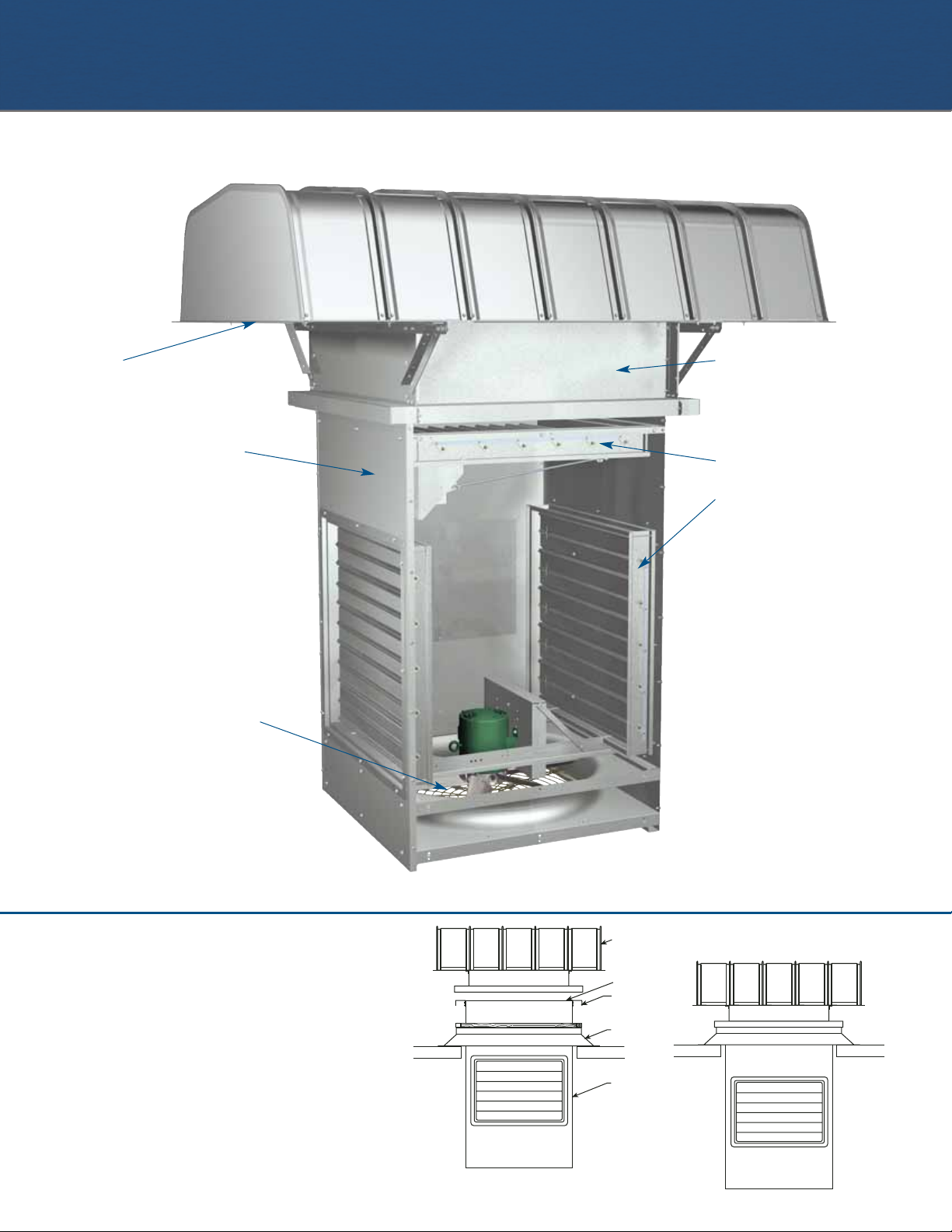
1. The roof curb is mounted and secured over
the roof opening.
2. The plenum (factory assembled) is lowered
through the curb and roof opening until its
mounting channels rest on the roof curb.
Lifting lugs are provided. (Fig. 1)
3. The fan hood is lowered onto the
curb/plenum assembly. (Fig. 1)
4. The hood and plenum are secured to the
roof curb. (Fig. 2)
Installation Sequence
3
Standard Construction Features
Fan hoods and bases are constructed of galvanized steel. Optional aluminum construction is available. Hood panels are arched
and precision roll formed for strength and weather tightness. They are bolted to heavy gauge support angles. All hood sizes ship
fully assembled except for 54 in. non-filtered, 48 in. and 54 in. filtered.
Birdscreens are constructed
of 1/2 in. galvanized steel
mesh. Optional filters are
available.
Plenums are galvanized
steel, supported at the roof
curb by mounting channels.
For servicing the fan two
removable access panels are
provided. Four lifting lugs are
provided for ease of
installation. (See important
plenum height information on
pg. 4.)
Protective guards mount to
the bottom of the plenum to
protect the fan and nearby
personnel.
Propellers are designed to
produce a high level of
efficiency over a broad
selection range. Tapered
airfoil blades are cast of
aluminum alloy. The propeller
is designed to deliver equal
airflow in the exhaust, supply,
and recirculation modes.
Each propeller is balanced
prior to assembly.
Bases are standard at 12
in. high with pre-punched
mounting holes for easy
installation.
A low leakage control
damper (exhaust/supply)
and two standard control
dampers (recirculation) are
linked for recirculation and
mixing. Construction
consists of galvanized
steel.
Standard damper
actuators are modulating
spring return.
Heavy-duty ball bearing
motors are carefully
matched to the fan load.
Motor support frames are
constructed of heavy
gauge steel angles.
Fan panels are
constructed of heavy
gauge steel with a double
venturi for efficient airflow.
Fig. 1
Hood
Lifting Lugs
Mounting
Channels
Roof
Curb
Plenum
Fig. 2
Page 4

Plenum Height Option
Plenum height can be increased in 12 in. increments to clear pitched roofs, beams and other solid obstructions
that may interfere with airflow into the
recirculation dampers. The standard
dimension from the top of the plenum
to the top of the recirculation
dampers is 20 in.
Installation Examples
Fig.1(left )- shows a truss type
that would not typically interfere with
airflow and does not require increasing
plenum height. Fig.1 (right )- shows a solid
beam obstruction requiring plenum
extension to clear.
The Fig. 2 installation requires extension
of the plenum to clear the pitch of the roof.
4
Options & Accessories
Filters
For applications where contaminants must be
removed from air supplied to the building, washable
2 in. aluminum mesh filters are available. Filters are
mounted in open end racks for easy removal. In fan
sizes 36 in. and larger, access panels are provided to
allow filter removal without raising the hood.
Roof Curbs
Prefabricated roof curbs are available to reduce
installation time and costs by ensuring compatibility
between the fan and the roof opening. See
Greenheck's roof curb catalog for
complete details. A wide
variety of roof curbs
are available, including:
flanged, pitched and
sound-absorbing.
Coatings
Special coatings are available for decorative or
protective purposes. Decorative coatings can be
applied to exterior surfaces of the hood, base and
plenum. Protection from corrosive atmospheres
requires individual consideration.
Disconnect Switches
NEMA 1 and NEMA 3R
disconnect switches are
available for positive electrical
shutoff and protection of
personnel. Disconnects are
shipped loose for field mounting.
Exhaust/Supply Damper Option
Insulated low leakage dampers are available for
applications where an indoor/outdoor temperature
differential must be maintained.
Hood Insulation
Hoods can be lined with 1/2 in. fiberglass insulation
to prevent condensation and reduce sound levels.
Motor Options
Motor enclosure options include open drip proof and
totally enclosed for single speed motors, and open
drip proof for two speed motors. Single phase motors
are available in 115/208/230 volt. Three phase motors
are available in 208/230/460 and 575 volt.
Tie-Down Points
Four galvanized steel brackets are available as cable
attachment points at the ends of each hood support
rail. Cable tie-downs prevent damage to the hood in
locations where unusually strong winds occur. (Cables
are by others.)
Diffusers
Discharge diffusers, mounted
to the bottom of the plenum,
offer the ability to direct the
airflow of the fan. Four
manually adjustable quadrants
can be set to direct air in any
direction desired. Construction
is galvanized steel. Guards are
necessary with or without
diffusers.
Fig. 2Fig. 1
20 in.
Standard
Dim. Req’d
to Clear Beam
Dim. Req’d to
Clear Roof Pitch
Page 5

5
The Control Center
Designed specifically for the Greenheck Four-Way fan,
the control center allows the operator to manually
change the modes of operation of the fan from a
convenient remote location.
This control center is more cost effective than controls
fabricated in the field. It offers savings in both time
and expense, since ease of installation, compatibility,
and qualities are assured. These units are complete,
self-contained control packages, with motor starters
included. (Wiring from the fan to the control center is
by others.)
Controls are housed in a NEMA 1 cabinet constructed
of heavy gauge steel and coated with Greenheck's
Permatector™ finish. A door interlocking disconnect
switch is provided to help prevent electrical shock
when the door is opened.
Operating Mode Combinations
Control centers are available in any one of the
following combinations, which must be specified when
ordering:
• ESRM-CC — Exhaust/Supply/Recirculate/Mix
• SRM-CC — Supply/Recirculate/Mix only
• ESR-CC — Exhaust/Supply/Recirculate only
• ER-CC — Exhaust/Recirculate only
Controls
Mode Selector
The mode selector switch is used to engage the
desired fan function. The four functions are described
below:
Exhaust Mode
Energizes the “reverse” contactor in the control center to allow the
fan to exhaust air from the building. The control also energies the
damper actuator, driving the top damper open, and the side dampers
closed. If the fan was previously running in the Supply, Recirculate, or
Mix mode, or the power was removed from the control center, there
will be a delay* before the fan starts again.
Supply Mode
Energizes the “forward” contactor in the control center to allow the
fan to supply air to the building and energizes the damper actuator,
driving the top damper open, and the side dampers closed. If the fan
was previously running in the Exhaust mode, or the power was
removed from the control center, there will be a time delay* before
the fan starts.
Recirculate Mode
Energizes the “forward” contactor in the control center to allow the
fan to recirculate air in the building. The damper actuator is not
energized, so the top damper remains closed and the side dampers
are open. If the fan was previously running in the Exhaust mode, or
the power was removed from the control center, there will be a time
delay* before the fan starts.
Mix Mode
Energizes the “forward”
contactor in the control center
to allow the fan to either
supply or recirculate the air in
the building. The damper
actuator is energized and is
modulated by the Honeywell
T775 temperature controller
located in the control cabinet.
The temperature controller is
programmable to either work in
a cool or heat mode, and to have temperature
setpoints. The operator would program the controller,
depending on the building needs, and the dampers would vary
position between supply and recirculate to try and maintain the
temperature programmed. If the fan was previously running in the
Exhaust mode, or the power was removed from the control center,
there will be a time delay* before the fan starts.
*Delay of 5 minutes for a 24 in. fan or 10 minutes for a 30 in. and larger.
Fans sized at 42 in. and smaller, one damper actuator motor is used in
the fan to position the dampers, with linkage tying them together.
For 48 in. and 54 in. fans, two actuator motors are used to position the
dampers, with linkage tying them together.
Temperature Control
Fans specified with the mix mode (ESRM or SRM only)
include a temperature controller . A remote
temperature sensor is field mounted below the fan
discharge in the airstream. The modulating damper
actuator(s) is driven by the solid state temperature
controller to open or close the exhaust/supply and
recirculation dampers as required to maintain the
preset temperature. In the other modes, it will display
the temperature at the plenum of the fan, but has no
effect on its operation.
Options
• An indicator light mounted on the control panel
door is available to indicate power to the fan.
• An access opening is provided in the door of units
with temperature controls to allow the control to be
adjusted with the door closed.
2
3
Control Center Model
(1 Speed, 3 Phase)
Number of Fans Per Control Center
1 2 3 4
ESRM-CC 24-42
ESRM-CC 48-54
SRM-CC 24-42
SRM-CC 48-54
ESR-CC 24-54
ER-CC 24-54
ES-CC 24-60
SR-CC 24-54
1
1
3
2
23 in.
6
4
⁄7
in.
Page 6

6
Performance Data
MODEL NUMBER RPM HP
MAX
BHP
SONES @
0.125
CFM / STATIC PRESSURE IN INCHES W.G.
0.000 0.125 0.250 0.375
ESRMD-24-420-B3 1160 1/3 0.37 20 4733 4023 2810
ESRMD-24-430-B5 1160 1/2 0.60 22 5525 4589 3109
ESRMD-24-415-A7 1750 3/4 0.89 33 6096 5700 5244 4685
ESRMD-24-420-A10 1750 1 1.26 42 7140 6711 6213 5659
ESRMD-24-622-A15 1750 11⁄2 1.77 43 8005 7747 7327 6921
ESRMD-30-427-C5 870 1/2 0.55 18.0 7595 5735 3303
ESRMD-30-418-B7 1160 3/4 0.85 29 8995 7945 6448 4393
ESRMD-30-425-B10 1160 1 1.15 30 9965 8698 7195 5192
ESRMD-30-625-B15 1160 11⁄2 1.59 35 11325 10326 9026 6757
ESRMD-30-415-A20 1750 2 2.30 59 12005 11398 10695 9985
ESRMD-30-420-A30 1750 3 3.23 61 14054 13328 12576 11768
ESRMD-30-625-A50 1750 5 5.46 73 17085 16463 15782 15046
ESRMD-36-410-C5 870 1/2 0.55 23 7899 5850 3156
ESRMD-36-614-C7 870 3/4 0.88 25 10062 8676 6800
ESRMD-36-620-C10 870 1 1.37 26 11554 10164 7440
ESRMD-36-626-C15 870 11⁄2 1.73 28 13424 11956 9487
ESRMD-36-615-B20 1160 2 2.39 45 13966 12858 11454 9974
ESRMD-36-623-B30 1160 3 3.66 46 17261 15948 14605 13369
ESRMD-42-413-C10 870 1 1.14 26 13175 11069 7950 4200
ESRMD-42-615-C15 870 11⁄2 1.73 27 16063 14358 12205 9001
ESRMD-42-620-C20 870 2 2.29 33 18275 16513 14260 11465
ESRMD-42-629-C30 870 3 3.38 35 21264 19373 17171 13941
ESRMD-42-621-B50 1160 5 5.63 55 24776 23430 22078 20377
ESRMD-48-618-F15 680 11⁄2 1.71 26 19446 16442 11939
ESRMD-48-616-F20 680 2 2.20 28 20886 18974 16481
ESRMD-48-623-F30 680 3 3.56 32 24368 22235 17320 14516
ESRMD-48-612-C20 870 2 2.31 38 20218 17864 15156 11386
ESRMD-48-617-C30 870 3 3.29 41 23020 20817 17930 14322
ESRMD-48-619-C50 870 5 5.66 45 28511 26885 25194 23287
ESRMD-48-618-B75 1160 71⁄2 8.52 66 32435 29892 29139 27139
ESRMD-48-620-B100 1160 10 11.85 74 36151 35143 34085 32966
ESRMD-54-615-F20 680 2 2.34 35 23198 19758 13768
ESRMD-54-620-F30 680 3 3.49 37 25875 22129 17205 11627
ESRMD-54-429-F50 680 5 5.70 44 32002 28710 24070 19075
ESRMD-54-614-C50 870 5 5.75 58 32687 30673 28684 26153
ESRMD-54-422-C75 870 71⁄2 8.39 60 37995 35786 33443 30137
ESRMD-54-624-C100 870 10 11.92 63 42762 40340 38331 35529
Shading indicates sound levels in excess of 50 sones (85 dBA) and are subject to OSHA regulations.
This catalog shows fan performance ratings with BHP's as much as 20% over the motor's nameplate horsepower. Motor life
is dependent on the operating temperature of the motor. Motors provided are sufficiently cooled to allow operation up to 20%
above their horsepower ratings. This does not reduce motor life or performance and therefore is economically desirable.
The model numbering system is designed to completely identify the fan. The correct code letters and numbers must be specified
to designate function, size, no. of blades, pitch, RPM & HP.
Model Number Code
Propeller Diameter
ESRMDF - 24 - 624 - B3
Model
Filter
(Optional)
Motor HP
4 = 1/4 7 = 3/4 30 = 3 100 = 10
3 = 1/3 10 = 1 50 = 5
5 = 1/2 20 = 2 75 = 7
1
⁄2
Number of Blades
Motor RPM
A = 1725 C = 870
B = 1140 F = 680
Propeller
Pitch
Page 7

7
Dimensional Data
All dimensions are in inches.
Due to Greenheck's policy of continuous product improvement, dimensions are subject to change without notice.
For complete dimensional information refer to the applicable submittals for this product.
Control Damper
OPTIONAL DIFFUSER
H
F
C
A Sq.
B Sq.
Roof Opening
*
20"
5"
G
DxE
Access
Door
Models ESRMD & ESRMDF
Model ERD
Top Damper Recirc. Damper Access Doors
Roof
Size A B C*
VCD-2120 VCD-1020
DE
Opening
24 40 32 58
1
⁄2 29 x 29 27w x 26h 21 20 341⁄2
30 46 38 63 35 x 35 33w x 30h 27 20 401⁄2
36 52 44 715⁄8 41 x 41 39w x 38h 33 22 461⁄2
42 58 50 753⁄4 47 x 47 44w x 42h 38 36 521⁄2
48 64 56 825⁄8 53 x 53 50w x 48h 44 36 581⁄2
54 70 62 91 59 x 59 56w x 54h 50 36 641⁄2
Non-Filtered Hood Filtered Hood Upblast Hood Approximate Unit Weights
Size ESRMD Hood Size ESRMDF Hood Size ERD Hood Size ESRDM ESRMDF ERD
F G H F G H F G H Alum Galv Alum Galv Alum Galv
24 63 66 30 63 66 30 21⁄2 313⁄8 261⁄4 570 650 670 750 400 480
30 75 74 32 75 78 32 31⁄2 373⁄8 303⁄8 760 900 860 1000 490 630
36 87 76 33 87 94 33 41⁄2 433⁄4 333⁄4 1040 1200 1170 1330 715 875
42 99 86 361⁄2 99 100 361⁄2 41⁄2 50 381⁄2 1200 1400 1330 1530 850 1050
48 111 100 361⁄2 111 112 361⁄2 51⁄2 561⁄4 41 1470 1700 1620 1850 1110 1340
54 111 112 39 112 124 39 51⁄2 633⁄8 45 1770 2000 1920 2150 1405 1635
*Important: Plenum height can be increased in 12 in. increments (to clear solid ceiling obstructions, etc.) Increases
will effect dimension C*. See page 4 for more information on plenum height.
G
Low Leakage Control Damper
A Sq.
OPTIONAL DIFFUSER
B Sq.
Roof Opening
H
12 in.
20 in.
*
C
E
5 in.
F
Low Leakage Control Damper
ACCESS DOOR
Control Damper
D
OPTIONAL DIFFUSER
Control Damper
Page 8

Greenheck warrants this equipment to be free from defects in material and workmanship for a period
of one year from the purchase date. Any units or parts which prove defective during the warranty
period will be replaced at our option when returned to our factory, transportation prepaid. Motors are
warranted by the motor manufacturer for a period of one year. Should motors furnished by Greenheck
prove defective during this period, they should be returned to the nearest authorized motor service
station. Greenheck will not be responsible for any removal or installation costs.
As a result of our commitment to continuous improvement, Greenheck reserves the right to change
specifications without notice.
P.O. Box 410 • Schofield, WI 54476-0410 • Phone (715) 359-6171 • greenheck.com
ESRMD Catalog Rev. 2 October 2005 SN
Copyright © 2005 Greenheck Fan Corp.
Greenheck delivers value to
mechanical engineers by
helping them solve virtually any
air quality challenges their
clients face with a
comprehensive selection of top
quality, innovative air-related
equipment. We offer extra value
to contractors by providing
easy-to-install, competitively
priced, reliable products that
arrive on time. And building
owners and occupants value
the energy efficiency, low
maintenance and quiet
dependable operation they
experience long after the
construction project ends.
Building Value in Air
Our Warranty
All exhaust, supply,
recirculating and modulating
power roof ventilators shall be
direct drive axial type.
Propeller construction shall be
cast aluminum, airfoil,
reversible design. Propellers
shall be statically and
dynamically balanced.
Fan hood and base
construction shall be
galvanized steel (aluminum
optional). Bases shall be 12 in.
high. Hood panels shall be
arched with interlocking
seams for weather protection.
Birdscreens constructed of 1/2
in. galvanized steel mesh shall
be mounted horizontally
across the discharge/intake
area of the hood. Hood
support members shall be
heavy gauge galvanized steel
angles.
Plenums shall be constructed
of galvanized steel (painted
steel optional). Plenum
mounting channels shall be
heavy gauge galvanized steel.
Access panels shall be
provided in each of two
opposing sides of the plenum.
Dampers shall be constructed
with galvanized steel frames
and blades. Exhaust/ supply
dampers shall be Greenheck
model VCD 2120 low leakage
control dampers. Recirculation
dampers shall be Greenheck
model VCD 1020 control
dampers. Damper actuators
for exhaust, supply and
recirculation fans shall be
modulating type with spring
returns.
Motors shall be heavy duty
ball bearing type carefully
matched to the fan load and
furnished at the specified
voltage, phase and enclosure.
A standard square key and set
screws or tapered lock
bushing shall attach the
propeller securely to the motor
shaft.
Motor support frame
assemblies shall be
constructed of heavy gauge
steel angles. Fan panels shall
be heavy gauge steel with
formed flanges and a double
venturi.
Performance shall be equal for
exhaust, supply and
recirculate modes.
Each unit shall bear a
permanently affixed nametag
with a fan model number, a
serial number, and a mark.
Optional control centers shall
bear a nametag with identical
information.
Hooded axial roof ventilators
shall be direct drive model
ESRMD (Four-Way Fan) as
manufactured by Greenheck,
Schofield, Wisconsin.
Typical Specifications
 Loading...