

Page 1
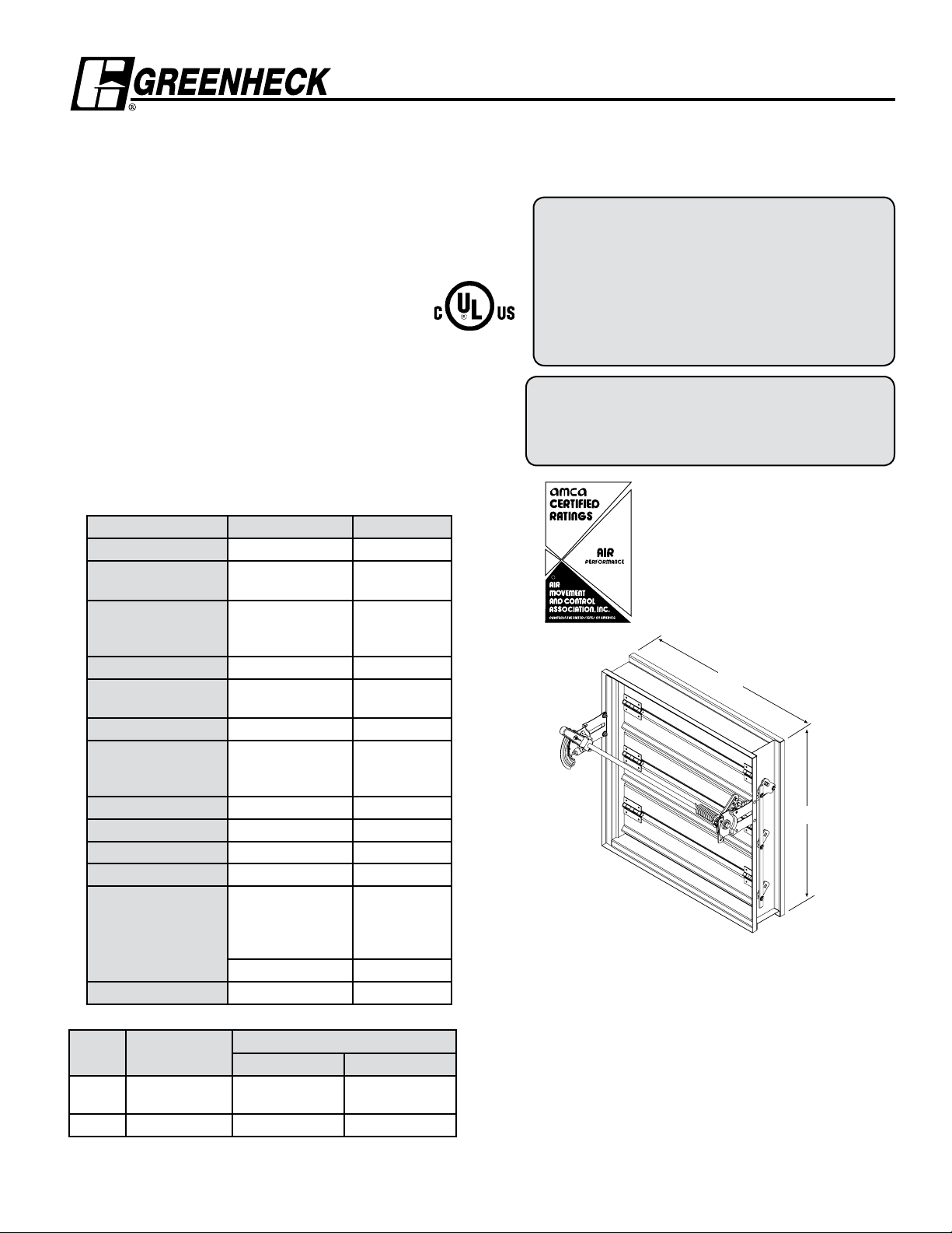
Model DFD-M210
R
Application
Model DFD-M210 is a multi-blade fire damper with 3V style blades.
The DFD-M210 has been qualified to 10.2 m/s (2000 fpm) and 1.0kPa
(4 in. wg.) for operation and dynamic closure in emergency fire
situations. Model DFD-M210 may be installed vertically (with blades
running horizontal) or horizontally and is rated for airflow in either
direction.
Model DFD-M210 has also been tested in accordance with BS476 to
4 hours at Warrrington Fire, UK, and is approved for fire partitions of 4
hours or less where British Standards are required.
Ratings
UL 555 Fire Resistance Rating
Fire Rating: 1
Dynamic Closure Rating: Actual limits are size dependent
Maximum Velocity: 20.3 m/s (4000 fpm) up to
813mm x 1270mm( 32 in. x 50 in.)
10.2 m/s (2000 fpm)sizes greater
than that.
Maximum Pressure: 2.5 kPa (10 in. wg)
BS476 Fire Resistance Rating
Fire Rating: 4 hours
Construction Standard Optional
Frame Material Galvanized steel -
Frame Material
Thickness
Frame Type 127mm x 25mm
Blade Material Galvanized steel -
Blade Material
Thickness
Blade Type 3V -
Linkage Plated steel out of
airstream, concealed
Axle Bearings Bronze -
Axle Material Plated steel -
Jamb Seals 304SS -
Closure Device Fusible link -
Closure Temperature
69°C (155°F) BS476 -
Actuator Manual quadrant -
W x H Minimum Size
mm 203 x 152 914 x 914 or
Inches 8 x 6 36 x 36 or 32 x 50 64 x 50
Installation instructions available at www.greenheck.com
1
⁄2 Hours
1.5mm
(16 ga.)
(5 in. x 1in.)
hat channel
1.5mm
(16 ga.)
in jamb
74°C (165°F) UL 100°C (212°F),
-
-
-
-
141°C (286°F),
177°C (350°F)
UL
Maximum Size
Single Section Multi-Section
813 x 1270
1626 x 1270
Multi-Blade FIRE DAMPER
Steel 3V Blades
UL555 11/2 Hour Fire Resistance Rating
4 hour Fire Resistance Rating (BS476)
Model DFD-M210 is intended for installation in
accordance with fire damper requirements
established by:
National Fire Protection Association
NFPA Standards 80, 90A & 101
IBC International Building Codes
British Standard BS476
Tested to 4 hours at Warrington Fire, UK
“UL CLASSIFIED (see complete marking on
product)”
“UL CLASSIFIED to Canadian safety standards
(see complete marking on product)”
Standard 555 (Listing #R13317)
Greenheck Kunshan Co. Ltd. and Greenheck Fan
Corporation certifies that the model DFD-M210
shown herein is licensed to bear the AMCA
Seal. The ratings shown are based on tests and
procedures performed in accordance with AMCA
Publication 511 and comply with the requirements
of the AMCA Certified Ratings Programs. The
AMCA Certified Ratings Seal applies to air
performance ratings only.
W
RH
LH
* W & H dimensions furnished approximately 6mm (1/4 in.) undersize.
(Add sleeve thickness for overall sleeved damper dimension)
Features
• Frames are constructed with reinforced corners. Low
profile head and sill are used on sizes less than 432mm
(17 in.) high.
• Blades are reinforced with 3 longitudinal structurally
designed vee's.
Options
• Extra Fusible Links
• Flanges
• OCI (Open Closed Indication switches)
• POC retaining angles
• Sleeves
• Transitions (R, C)
H
Page 2
Pressure Drop Data DFD-M210
5D 6D
5D
D
4 (W) (H
)
3.14
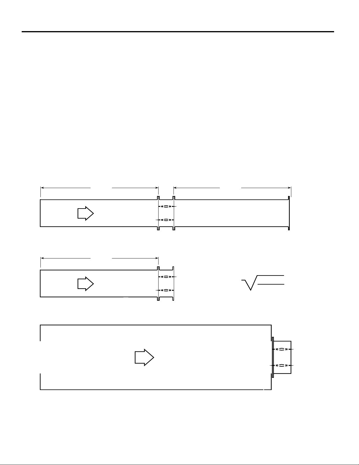
This pressure drop testing was conducted in accordance with AMCA Standard 500-D using the three configurations shown. All
data has been corrected to represent standard air at a density of 1.201 kg/m3.
Actual pressure drop found in any HVAC system is a combination of many factors. This pressure drop information along with an
analysis of other system influences should be used to estimate actual pressure losses for a damper installed in a given HVAC
system.
AMCA Test Figures
Figure 5.3 Illustrates a fully ducted damper. This configuration has the lowest pressure drop of the three test configurations
because entrance and exit losses are minimized by straight duct runs upstream and downstream of the damper.
Figure 5.2 Illustrates a ducted damper exhausting air into an open area. This configuration has a lower pressure drop than
Figure 5.5 because entrance losses are minimized by a straight duct run upstream of the damper.
Figure 5.5 Illustrates a plenum mounted damper. This configuration has the highest pressure drop because of extremely high
entrance and exit losses due to the sudden changes of area in the system.
Page 3

AMCA 5.2 Pressure Drop DFD-M210
5D 6D
D
4 (W) (H)
3.14
R
5D
VELOCITY VS. PRESSURE DROP
1000
305mm x 305mm
610mm x 610mm
914mm x 914mm
305mm x 1219mm
1219mm x 305mm
610 x 610
914 x 914
1219 x 305
305 x 1219
100
305 x 305
305mm x 305mm
Velocity
(m/s)
Pressure
Drop (Pa)
2.5 10
5.1 35
7.7 80
10 135
12.6 207
15.5 311
17.8 411
20.8 561
10
PRESSURE DROP- PASCALS
2 5 10 30
FACE VELOCITY- METERS/SECOND
AMCA 5.2
610mm x 610mm
Velocity
(m/s)
Pressure
Drop (Pa)
2.5 5
5.2 17
7.8 42
10.3 72
12.9 115
15.4 162
18.1 224
20.8 296
914mm x 914mm
Velocity
(m/s)
2.6 3
5.1 10
7.6 22
10.2 42
12.7 65
15.3 95
17.7 127
20.3 167
Pressure
Drop (Pa)
305mm x 1219mm
Velocity
(m/s)
Pressure
Drop (Pa)
2.5 3
5.1 15
7.6 32
10.3 57
12.9 90
15.3 125
18 174
20.5 227
1219mm x 305mm
Velocity
(m/s)
Pressure
Drop (Pa)
2.5 8
5.1 27
7.7 57
10.3 105
12.9 164
15.6 242
17.9 316
20.7 424
Greenheck Kunshan Co. Ltd. and Greenheck Fan
Corporation certifies that the model DFD-M210
shown herein is licensed to bear the AMCA Seal. The
ratings shown are based on tests and procedures
performed in accordance with AMCA Publication
511 and comply with the requirements of the AMCA
Certified Ratings Programs. The AMCA Certified
Ratings Seal applies to air performance ratings only.
Page 4

R
AMCA 5.3 Pressure Drop DFD-M210
5D 6D
VELOCITY VS. PRESSURE DROP
1000
305mm x 305mm
610mm x 610mm
914mm x 914mm
305mm x 1219mm
1219mm x 305mm
1219 x 305
100
305 x 305
305 x 1219
PRESSURE DROP- PASCALS
305mm x 305mm
Velocity
(m/s)
2.4 5
5.1 22
7.8 52
10.3 92
12.9 145
15.4 209
17.7 274
20.8 379
Pressure
Drop (Pa)
610 x 610
914 x 914
10
2 5 10 30
FACE VELOCITY- METERS/SECOND
AMCA 5.3
610mm x 610mm
Velocity
(m/s)
2.5 3
5 10
7.7 22
10.3 40
12.8 62
15.5 92
17.9 122
20.8 167
Pressure
Drop (Pa)
914mm x 914mm
Velocity
(m/s)
2.5 3
5.1 8
7.6 15
10.1 27
12.8 42
15.3 62
17.7 82
20.3 107
Pressure
Drop (Pa)
305mm x 1219mm
Velocity
(m/s)
2.5 3
5.1 10
7.7 25
10.3 42
12.9 67
15.7 100
18.7 140
20.9 174
Pressure
Drop (Pa)
1219mm x 305mm
Velocity
(m/s)
2.5 5
5.1 20
7.6 40
10.1 72
12.7 112
15.3 164
18 227
20.6 299
Pressure
Drop (Pa)
Greenheck Kunshan Co. Ltd. and Greenheck Fan
Corporation certifies that the model DFD-M210
shown herein is licensed to bear the AMCA Seal. The
ratings shown are based on tests and procedures
performed in accordance with AMCA Publication
511 and comply with the requirements of the AMCA
Certified Ratings Programs. The AMCA Certified
Ratings Seal applies to air performance ratings only.
Page 5

R
AMCA 5.5 Pressure Drop DFD-M210
5D 6D
5D
D
4 (W) (H)
3.14
VELOCITY VS. PRESSURE DROP
1000
305mm x 305mm
610mm x 610mm
914mm x 914mm
305mm x 1219mm
1219mm x 305mm
305 x 1219
914 x 914
610 x 610
1219 x 305
100
305 x 305
305mm x 305mm
Velocity
(m/s)
2.5 13
5 55
7.5 122
10.2 222
12.7 349
15.4 508
17.9 688
20.6 907
Pressure
Drop (Pa)
10
PRESSURE DROP- PASCALS
2 5 10 30
610mm x 610mm
Velocity
(m/s)
2.5 8
5 35
7.6 75
10.3 140
12.8 217
15.3 309
17.7 409
20.8 568
FACE VELOCITY- METERS/SECOND
Pressure
Drop (Pa)
AMCA 5.5
914mm x 914mm
Velocity
(m/s)
2.5 8
5.1 30
7.7 67
10.2 115
12.9 184
15.5 269
18.1 354
20.6 471
Pressure
Drop (Pa)
305mm x 1219mm
Velocity
(m/s)
2.6 8
5.1 32
7.7 75
10.2 130
12.7 202
15.5 301
18.1 416
20.6 536
Pressure
Drop (Pa)
1219mm x 305mm
Velocity
(m/s)
2.5 1
5 42
7.7 95
10.3 172
12.7 264
15.3 381
17.9 521
20.8 707
Pressure
Drop (Pa)
Greenheck Kunshan Co. Ltd. and Greenheck Fan
Corporation certifies that the model DFD-M210
shown herein is licensed to bear the AMCA Seal. The
ratings shown are based on tests and procedures
performed in accordance with AMCA Publication
511 and comply with the requirements of the AMCA
Certified Ratings Programs. The AMCA Certified
Ratings Seal applies to air performance ratings only.
Page 6

DIMENSIONAL DATA SPECIFICATIONS
Damper Sizing Information
The following figure shows maximum damper section size.
Multi Section
Single Section
1270mm
H
w
914mm x 914mm
or
813mm x 1270mm
813mm
1626mm
Damper Sleeve Dimensional Data
The drawings below and corresponding table show the position of the DFD-M210 damper when mounted in a factory sleeve.
The standard mounting locations provide enough space for the mounting of manual quadrant, controls and allow space for
installation of retaining angles and duct connections.
The “A” dimension is the location of the damper mounted in a
factory sleeve. The table below shows the Standard, Minimum,
and Maximum “A” dimensions.
"A" Dimension
Standard Minimum Maximum
All Dampers 183mm 137mm 406mm
1
All dampers w/o OCI.
Note: Entire damper frame is not required to be installed
within the wall.
The damper blades, when closed, should be contained
in the wall.
152mm
LH RH
Right hand drive is shown
Left hand drive available upon request
Varies
95mm
137mm
A
Sleeve Length
38mm max.
127mm
Specifications
Fire Dampers meeting the following specifications shall be furnished and
installed where shown on plans and/or as described in schedules. Dampers
shall meet the requirements of the latest edition of NFPA 80, 90A and 101.
Dampers shall be tested, rated and labeled in accordance with the latest
edition of UL Standard 555. Dampers shall have a UL 555 fire rating of
1½ hours. Each damper shall be equipped with a heat responsive device
which has been tested and approved for use with the damper assembly
in accordance with UL 555. The heat responsive device shall have a
temperature rating of (specifier select one of the following) 74ºC, 100ºC,
141ºC, or 177ºC. Dampers shall be UL labeled for use in dynamic systems.
The damper shall have a dynamic closure pressure rating of 1 kPa.
Damper actuator shall be manual quadrant. Manufacturers submittal data
shall indicate actuator space requirements around the damper.
The Damper Manufacturers submittal data shall certify all air performance
pressure drop data is licensed in accordance with the AMCA Certified
Ratings Program for Test Figures 5.2, 5.3 and 5.5. Damper air performance
data shall be developed in accordance with the latest edition of AMCA
Standard 500-D.
Damper blades shall be 1.5mm galvanized steel 3V type with three
longitudinal grooves for reinforcement. Blades shall be completely
symmetrical relative to their axle pivot point, presenting identical resistance
to airflow and operation in either direction through the damper (blades that
are non-symmetrical relative to their axle pivot point or utilize blade stops
larger than 13mm are unacceptable).
Damper frame shall be 1.5mm galvanized steel formed into a structural hat
channel shape with reinforced corners. Bearings shall be sintered bronze
sleeve type rotating in extruded holes in the damper frame for maximum
service. Axles shall be square and positively locked into the damper blade.
Jamb seals shall be stainless steel compression type.
Basis of design is Greenheck Model DFD-M210.
Copyright © 2010 Greenheck Fan Corpation
DFD-M210 Rev. 5 November 2010
 Loading...