

Page 1
Application
Model FD-M150 is approved for use in walls, floors and
partitions with fire resistance ratings less than 3 hours.
This model carries a 11⁄2 hour UL fire damper label. UL 555
classifies static rated fire dampers for use in HVAC systems
that are automatically shut down in the event of fire .
Construction
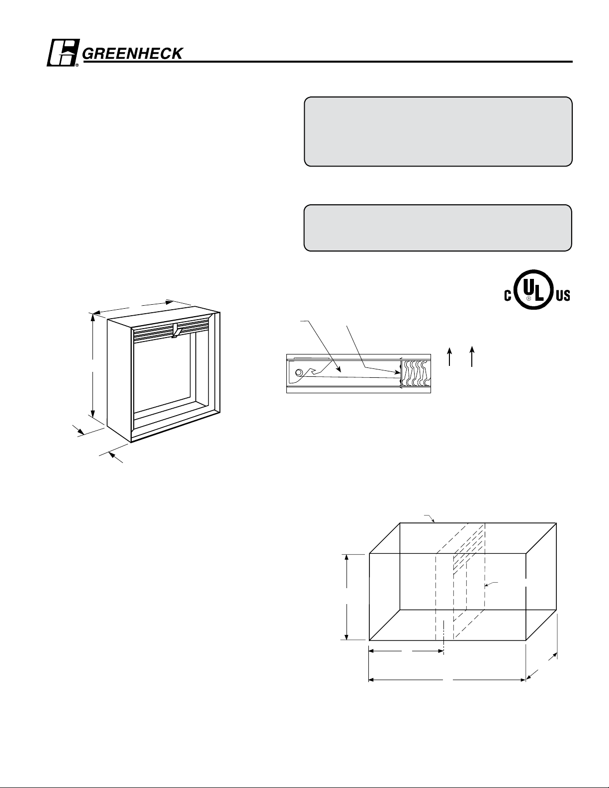
Galvanized steel (in gauges required by UL listing R13317)
Model FD-M150
Static Rated Fire Dampers
1 1/2 Hour Fire Resistance Rating
Model FD-M150 meets the requirements for fire dampers
established by:
National Fire Protection Association
(NFPA Standards 80, 90A & 101)
IBC International Building Codes
Installation
All fire damper installations require the use of sleeves,
angles and methods described in Greenheck Fire Damper
Installation Instructions #464089, included with every
damper shipment. Sleeves can be field fabricated or factory
furnished as a complete damper/sleeve assembly. See
Factory Sleeve Option below for details.
W*
Stainless Steel
Closure Spring
H*
94mm
VERTICAL MOUNT
“UL CLASSIFIED (see complete marking on product)”
“UL CLASSIFIED to Canadian safety standards (see
complete marking on product)”
Standard 555 (Listing #R13317)
Fusible Link (replaceable)
74° C Standard (100° C available)
“K” Side
HORIZONTAL MOUNT
* These dimensions are furnished approximately
6mm undersize. (Add sleeve thickness for overall
sleeved damper dimension)
Factory Sleeve Option
FD-M150 Fire Dampers are available in factory furnished sleeves.
Sleeves are galvanized steel and are available in 1.0mm - 1.5mm
thicknesses and lengths up to 914mm .
“K” dimension specifies location of damper within the sleeve.
Minimum is 102mm, maximum is “L” less 102mm, which allows
for mounting angle installation and duct connection at each end of
sleeve. If “K” dimension is not specified, it will be provided as one
half of “L” dimension (damper centered in sleeve).
Horizontal dampers must be installed with the “K” dimension on the
bottom side.
Installation instructions available at www.greenheck.com
Sleeve
Damper
H*
K
Damper
Location
Overall Sleeve Length
CL Damper Frame
L
W*
Page 2
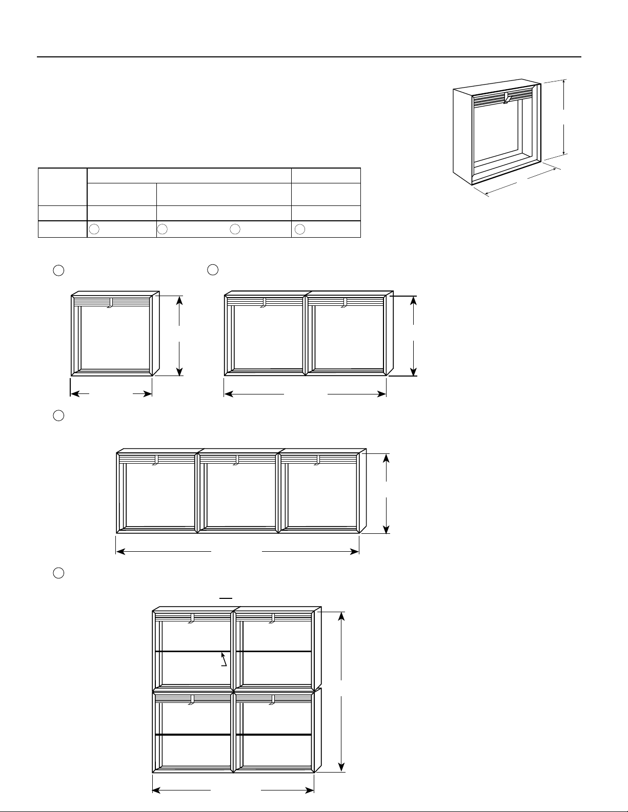
Dampers larger than maximum single section size are supplied in 2 or more sections
of equal size. If ordered with a factory sleeve, multi-section dampers are factory
assembled ready for installation. If ordered without a factory sleeve, multi-section
dampers require field assembly. (See Greenheck Fire Damper Installation Instructions
#464089)
The following chart and illustrations show minimum and maximum damper section size
and assembly configurations for multi-section dampers.
Size Limitations
Single Multi- Multi mm Section Section Section
Minimum 102 x 102 NA NA
Maximum 1219 x 1219 2438 x 1219 or 3048 x 1016 1880 x 1880
Installation of sizes larger than the maximums shown requires approval of the authority
having jurisdiction.
1
1 2 3
Maximum Single
Vertical or Horizontal
2
Section Dimensions
Vertical
4
Multi-Section Limitations
Maximum height is 1219mm when width is 2438mm or less.
FD-M150 TYPE ASIZING DATA
H*
W*
1219mm max.
1219mm max.
Multi-Section Limitations
3
Maximum height is 1016mm when width is greater than 2438mm and less
than or equal to 3048mm.
3048mm max.
Multi-Section Limitations
4
Maximum height is 1880mm when width is less than or equal to 1880mm. (Vertical mullion
provided on
dampers over 940mm wide
and 1219mm high. )
2438mm max.
1219mm max.
1016mm max.
Reinforcement
Rods
1880mm max.
1880mm max.
Page 3

Maximum Single
Dampers larger than maximum single section size are supplied in 2 or more
sections of equal size. If ordered with a factory sleeve, multi-section dampers are
factory assembled ready for installation. If ordered without a factory sleeve, multisection dampers require field assembly. (See Greenheck Fire Damper Installation
Instructions #464089)
The following chart and illustrations show minimum and maximum damper section
size and assembly configurations for multi-section dampers.
Size Limitations
Single Multi- Multi mm Section Section Section
Minimum 102 x76 NA NA
Maximum 1219 x 1092 2438 x 1092 or 3048 x 889 1880 x 1753
Installation of sizes larger than the maximums shown requires approval of the authority
having jurisdiction.
1
Section Dimensions
1219mm max.
Multi-Section Limitations
3
Maximum height is 889mm when width is greater than 2438mm and less than
or equal to 3048mm.
Multi-Section Limitations
4
Maximum height is 1753mm when width is less than or equal to 1880mm. (V
provided on dampers over 940mm wide and 1092mm high.)
Vertical or Horizontal Vertical
1 2 3
Multi-Section Limitations
2
Maximum height is 1092mm when width is 2438mm or less
1092mm max.
3048mm max.
Reinforcement
Rods
2438mm max.
1753mm max.
4
889mm max.
ertical mullion
1092mm max.
FD-M150 TYPE BSIZING DATA
Overall Damper
H* O*
76 127
102 152
127 178
152 203
178 229
203 254
229 279
254 305
279 330
305 356
330 381
356 406
381 457
406 483
432 508
457 533
483 559
508 584
533 610
559 660
584 686
610 711
635 737
660 762
686 787
711 813
737 838
762 864
787 889
813 914
838 965
864 991
889 1016
914 1041
940 1067
965 1092
991 1118
1016 1143
1041 1168
1067 1194
1092 1219
Dimensions
W*
H* O*
1118 1219
1143 1245
1163 1270
1194 1295
1219 1321
1245 1346
1270 1372
1295 1397
1321 1422
1346 1448
1372 1473
1397 1499
1422 1524
1448 1549
1473 1575
1499 1600
1524 1626
1549 1651
1575 1676
1600 1702
1626 1727
1651 1778
1676 1803
1702 1829
1727 1854
1752 1880
H*
O*
1880mm max.
These dimensions are furnished approximately
*
6mm undersize. (All ‘H’ dimensions larger than
1092mm are two sections high. The bottom
section is a Type A and the top section is a
Type B.)
Page 4

Dampers larger than maximum single section size are supplied as
a factory assembly of two or more sections of equal size.
Transition is centered on damper frame (or frame assembly for
multiple section dampers).
SIZE LIMITATIONS
Vertical or Horizontal Vertical Only
Minimum 76mm dia. NA
Maximum 1168mm dia. 1829mm dia.
Maximum size based on 51mm offset.
Type ‘R’ dampers over 1829mm dia. utilize
reinforcement rods and a vertical mullion.
FD-M150 TYPE RSIZING DATA
76mm min.
1829mm max.
GREENHECK
P.O. BOX 410 SCHOFIELD, WISCONSIN 54476-0410
PH. 715-359-6171
www.greenheck.com
Copyright © 2006 Greenheck Fan Corporation
FD-M150 Rev 3 July 2006
 Loading...