

Page 1

Model DFDAF-330
Application
Model DFDAF-330 is a multi-blade fire damper with airfoil style
blades for use in walls, floors, and partitions with fire resistance
rating of 3 hours or more. The DFDAF-330 is qualified to 4,000
fpm (20.3 m/s) and 8 in. wg (2 kPa) for dynamic closure in
emergency fire situations. Model DFDAF-330 may be installed
vertically or horizontally (with blades running horizontal) and is
rated for airflow in either directions.
Ratings
UL 555 Fire Resistance Rating
Fire Rating: 3 Hour
Dynamic Closure Rating: Actual ratings are size dependent
Velocity: Up to 4,000 fpm (20.3 m/s) on sizes
up to 32 in. x 36 in.
(813mm x 914mm); 2,000 fpm
(10.2 m/s) on sizes greater than
32 in. x 36 in. (813mm x 914mm)
Pressure: Up to 8 in. wg (2 kPa)
Construction Standard Optional
Frame Material Galvanized steel -
Frame Material
Thickness
Frame Type
Blade Material Galvanized steel -
Blade Material
Thickness
Blade Type Double skin airfoil -
Linkage
Axle Bearings 316SS -
Axle Material Plated steel -
Jamb Seals Stainless Steel -
Closure Device Fusible link -
Closure
Temperature
Actuator Manual quadrant -
Features
• Frames are constructed with reinforced corners. Low
profile head and sill are used on sizes less than 17
in. (432mm) high.
• Blades are double skin airfoil shape of galvanized
steel with full length structural reinforcement.
16 ga. (1.5mm) -
5 in. x 1 in.
(127mm x 25mm)
hat channel
14 ga. (2mm)equivalent -
Plated steel out of
airstream, concealed
in jamb
212°F (100°C),
165°F (74°C)
286°F (141°C),
350°F (177°C)
-
-
W x H
Inches 8 x 6
mm 203 x 152
Multi-blade FIRE DAMPER
Steel Airfoil Blades
UL555 3 Hour Fire Resistance Rating
*W & H dimensions furnished approximately 1⁄4 in. ( 6 mm)
undersize in case of nominal sizing only.
(Add sleeve thickness for overall sleeved damper dimension)
Model DFDAF-330 meets the requirements for fire
dampers established by:
National Fire Protection Association
NFPA Standards 80, 90A & 101
IBC International Building Codes
See complete marking on
product.
UL 555 Classification
R13317
Maximum Size
Minimum
Size
Single
Section
32 x 36 (V)
or
30 x 48 (H or V)
813 x 914
or
762 x 1219
Multi-Section
2000 fpm
(10.2 m/s)
120 x 96 (V)
or
144 x 96 (H)
3048 x 2438
or
3658 x 2438
4000 fpm
(20.3 m/s)
30 x 48 (V)
762 x 1219
Installation instructions available at www.greenheck.in
Page 2
5D 6D
5D
D
4 (W) (H)
3.14
5D 6D
Options & Pressure Drop Data DFDAF-330
Options available for DFDAF-330:
• Factory mounted accessories
- Retaining angles
- Quick connect breakaway connections
- Slip & Drive connections
- TDF Flange
• OCI (Open Closed Indication switches): Units will
be supplied with one OCI per row per separately
controlled section
Pressure Drop Data
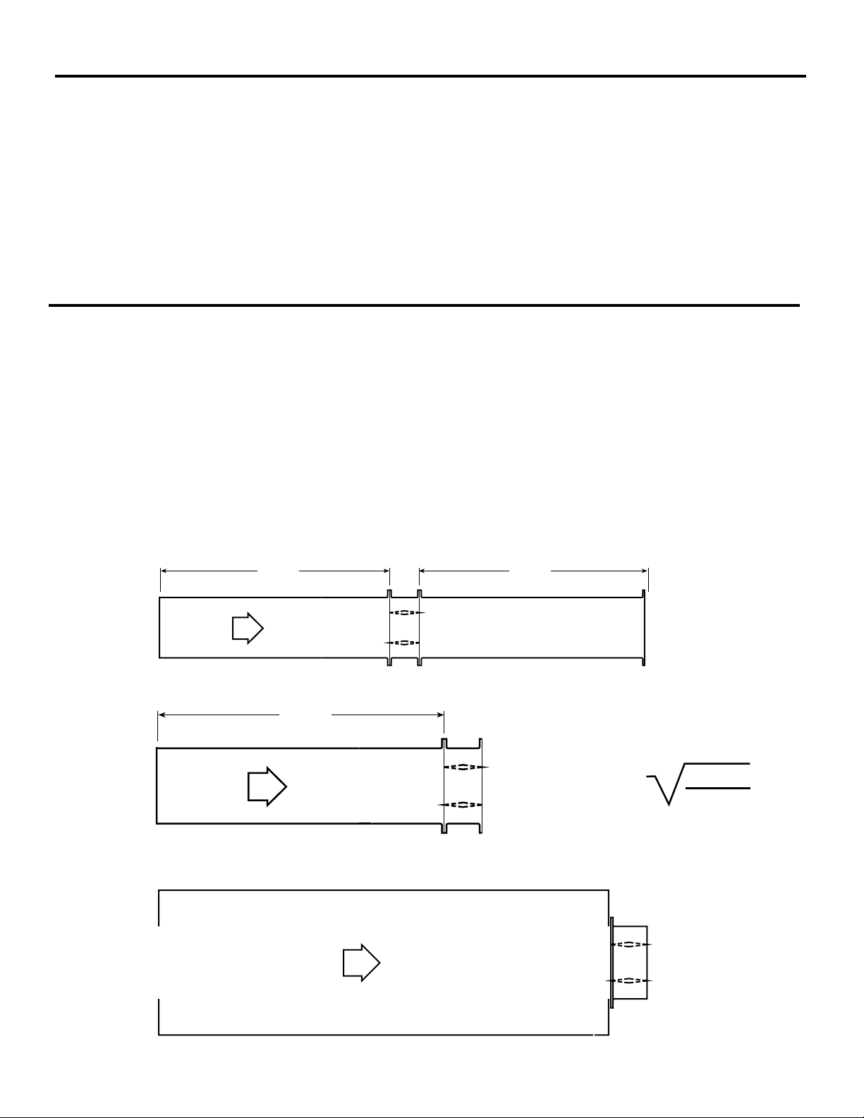
This pressure drop testing was conducted in accordance with AMCA Standard 500-D using the three configurations
shown. All data has been corrected to represent standard air at a density of .075 lb/ft3(1.201 kg/m3).
Actual pressure drop found in any HVAC system is a combination of many factors. This pressure drop information
along with an analysis of other system influences should be used to estimate actual pressure losses for a damper
installed in a given HVAC system.
AMCA Test Figures
Figure 5.3 Illustrates a fully ducted damper. This configuration has the lowest pressure drop of the three test
configurations because entrance and exit losses are minimized by straight duct runs upstream and downstream of the
damper.
Figure 5.2 Illustrates a ducted damper exhausting air into an open area. This configuration has a lower pressure drop
than Figure 5.5 because entrance losses are minimized by a straight duct run upstream of the damper.
Figure 5.5 Illustrates a plenum mounted damper. This configuration has the highest pressure drop because of
extremely high entrance and exit losses due to the sudden changes of area in the system.
• POC retaining angles
• Sleeves
• Transition (R)
5D 6D
Figure 5.3
5D
Figure 5.2
D
4 (W) (H
3.14
)
Figure 5.5
Page 3
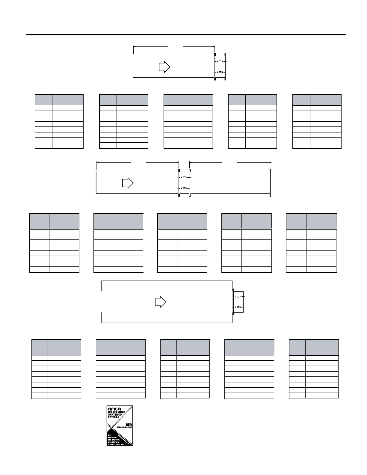
AMCA Pressure Drop DFDAF-330
Velocity
(fpm)
Pressure Drop
(in. wg)
Velocity
(fpm)
Pressure Drop
(in. wg)
Velocity
(fpm)
Pressure Drop
(in. wg)
Velocity
(fpm)
Pressure Drop
(in. wg)
Velocity
(fpm)
Pressure Drop
(in. wg)
500 0.03 500 0.01 500 0.01 500 0.01 500 0.02
1000 0.12 1000 0.06 1000 0.061000 0.051000 0.08
1500 0.26 1500 0.12 1500 0.121500 0.12 1500 0.18
2000 0.46 2000 0.22 2000 0.222000 0.21 2000 0.33
2500 0.72 2500 0.34 2500 0.342500 0.332500 0.51
3000 1.04 3000 0.49 3000 0.493000 0.483000 0.74
3500 1.41 3500 0.67 3500 0.673500 0.653500 1.00
4000 1.84 4000 0.87 4000 0.884000 0.854000 1.31
12in. X 48 in.
(
305mm x 1219mm) 48 in. x 12 in. (1219mm x 305mm) 24 in. x 24 in. (610mm x 610mm) 36in. x 36 in. (914mm x 914mm) 12 in. x 12 in. (305mm x 305mm)
5D 6D
5D
Figure 5.3
Figure 5.2
D
=
4 (W) (H)
3.14
5D 6D
5D
D
4 (W) (H)
3.14
Velocity (fpm)
Pressure Drop
(in. wg) Velocity (fpm)
Pressure Drop
(in. wg) Velocity (fpm)
Pressure Drop
(in. wg)Velocity (fpm)
Pressure Drop
(in. wg)Velocity (fpm)
Pressure Drop
(in. wg)
500 0.01 500 0.01 500 0.01 500 0.01 500 0.01
1000 0.06 1000 0.02 1000 0.02 1000 0.02 1000 0.04
1500 0.13 1500 0.06 1500 0.05 1500 0.06 1500 0.10
2000 0.23 2000 0.10 2000 0.09 2000 0.10 2000 0.18
2500 0.37 2500 0.16 2500 0.14 2500 0.16 2500 0.29
3000 0.53 3000 0.23 3000 0.21 3000 0.24 3000 0.42
3500 0.73 3500 0.32 3500 0.29 3500 0.33 3500 0.57
4000 0.95 4000 0.42 4000 0.38 4000 0.43 4000 0.74
24 in. x 24 in.
(
610mm x 610mm)36in. x 36 in. (914mm x 914mm
)
12in. X 48 in. (305mm x 1219mm)48 in. x 12 in. (1219mm x 305mm
)
12 in. x 12 in. (305mm x 305mm
)
Velocity
(fpm)
Pressure Drop
(in. wg)
Velocity
(fpm)
Pressure Drop
(in. wg)
Velocity
(fpm)
Pressure Drop
(in. wg)
Velocity
(fpm)
Pressure Drop
(in. wg)
Velocity
(fpm)
Pressure Drop
(in. wg)
5000.04500 0.03 5000.03500 0.03 5000.03
1000 0.18 1000 0.13 1000 0.12 1000 0.12 1000 0.14
1500 0.42 1500 0.29 1500 0.27 1500 0.27 1500 0.32
2000 0.75 2000 0.52 2000 0.48 2000 0.49 2000 0.57
2500 1.17 2500 0.81 2500 0.75 2500 0.77 2500 0.89
3000 1.68 3000 1.17 3000 1.08 3000 1.11 3000 1.28
3500 2.29 3500 1.60 3500 1.48 3500 1.51 3500 1.75
4000 2.99 4000 2.14 4000 1.93 4000 1.97 4000 2.29
24 in. x 24 in.
(
610mm x 610mm
)
36in. x 36 in. (914mm x 914mm)12in. X 48 in. (305mm x 1219mm)48 in. x 12 in. (1219mm x 305mm
)
12 in. x 12 in. (305mm x 305mm
)
AMCA Figure 5.2
AMCA Figure 5.3
AMCA Figure 5.5
5D 6D
Figure 5.3
Greenheck India Private Limited certifies that
the model DFDAF-330 shown herein is licensed
to bear the AMCA Seal. The ratings shown are
based on tests and procedures performed in
accordance with AMCA Publication 511 and
comply with the requirements of the AMCA
Certified Ratings Programs. The AMCA Certified
Ratings Seal applies to air performance ratings
only.
Page 4
36 in.
96 in. (2435mm)
(914mm)
32 in. (813mm)
48 in.
32 in. (813mm)
64 in. (1626mm)
36 in.
96 in. (2435mm)
(1219mm)
(914mm)
32 in. (813mm)
Damper Sizing Information
A
5 in.
Sideplate
Length**
6 in.
53/8 in.
5 in.A
Sleeve Length
Varies
33/4 in.
11/2 in. max.
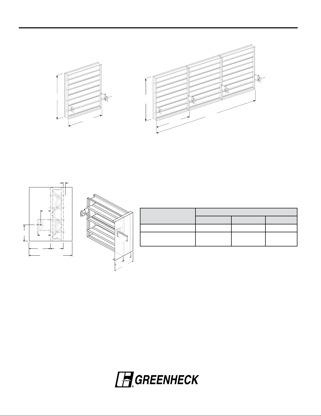
Dampers larger than maximum single section size are supplied as a factory assembly of two or more sections of equal
size. The following figures show maximum damper section size and assembly configurations for multi-section dampers.
Larger damper sizes may ship in multiple sections.
Single Section
36 in.
(914mm)
Multi-Section
32 in. (813mm)
Damper Sleeve Dimensional Data
The drawings below and corresponding table show the position of the DFDAF-330 damper when mounted in a factory
sleeve. The standard mounting locations provide enough space for the mounting of manual quadrant, controls and
allow space for installation of retaining angles and duct connections.
The “A” dimension is the location of the damper mounted in a factory sleeve. The table below shows the Standard and
Maximum “A” dimensions.
11/2 in.
max.
Sideplate
33/
Varies
4
in.
53/8
in.
A
Sleeve Length
Sleeve
in. (mm)
All Dampers 7
When Height is 11 in.
(279) or less with OCI
5
in.
NOTE: Entire damper frame is not required to be installed within the wall. The
Sleeve Std Sleeve Max Sideplate
3
⁄16 in. (183) 16 (406) 63⁄16 (157)
12 (305) 16 (406) 12 (305)
damper blades, when closed should be contained within the wall.
"A" Dimension
Specifications
Fire Dampers meeting the following specifications shall be furnished
and installed where shown on plans and/or as described in schedules.
Dampers shall meet the requirements of the latest edition of NFPA 80,
90A and 101.
Dampers shall be tested, rated and labeled in accordance with the
latest edition of UL Standard 555. Dampers shall have a UL 555
fire rating of 3 hours. Each damper shall be equipped with a heat
responsive device which has been tested and approved for use with
the damper assembly in accordance with UL 555. The heat responsive
device shall have a temperature rating of (specifier select one of the
following) 165°F (74°C), 212°F (100°C), or 350°F (177°C).
Dampers shall be UL labeled for use in dynamic systems. The damper
shall have a dynamic closure pressure rating of 4 in. wg (1 kPa) or
8 in. wg (2 kPa). UL 555 Dynamic Closure Ratings shall be qualified
for airflow and pressure in either direction through the damper. UL
ratings shall allow for mounting damper vertically (with blades running
horizontal) or horizontally.
Greenheck India: 201-202, 2nd Floor, Landmark Cyber Park, Sector 67, Gurgaon
Damper actuator shall be manual quadrant. Manufacturer's submittal
data shall indicate actuator space requirements around the damper.
Damper blades shall be 14 ga. (2mm) galvanized steel airfoil style.
Blades shall be completely symmetrical relative to their axle pivot
point, presenting identical resistance to airflow and operation in either
direction through the damper (blades that are non-symmetrical relative
to their axle pivot point or utilize blade stops larger than 1⁄2 in. (13mm)
are unacceptable).
Damper frame shall be 16 ga. (1.5mm) galvanized steel formed into a
structural hat channel shape with reinforced corners. Bearings shall
be 316SS type rotating in extruded holes in the damper frame for
maximum service. Axles shall be square and positively locked into the
damper blade. Jamb seals shall be stainless steel compression type.
Testing and ratings to be in accordance with AMCA standard 500-D.
Basis of design is Greenheck Model DFDAF-330.
Copyright © 2020 Greenheck India Private Limited
DFDAF-330 Rev. 5 December 2020
 Loading...