

Page 1
Document 462865
Hinge Kit
®
G/GB - Sizes 220-540
CUE/CUBE - Sizes 220-480
Installation, Operation and Maintenance Manual
Please read and save these instructions for future reference. Read carefully before attempting to assemble,
install, operate or maintain the product described. Protect yourself and others by observing all safety
information. Failure to comply with instructions could result in personal injury and/or property damage!
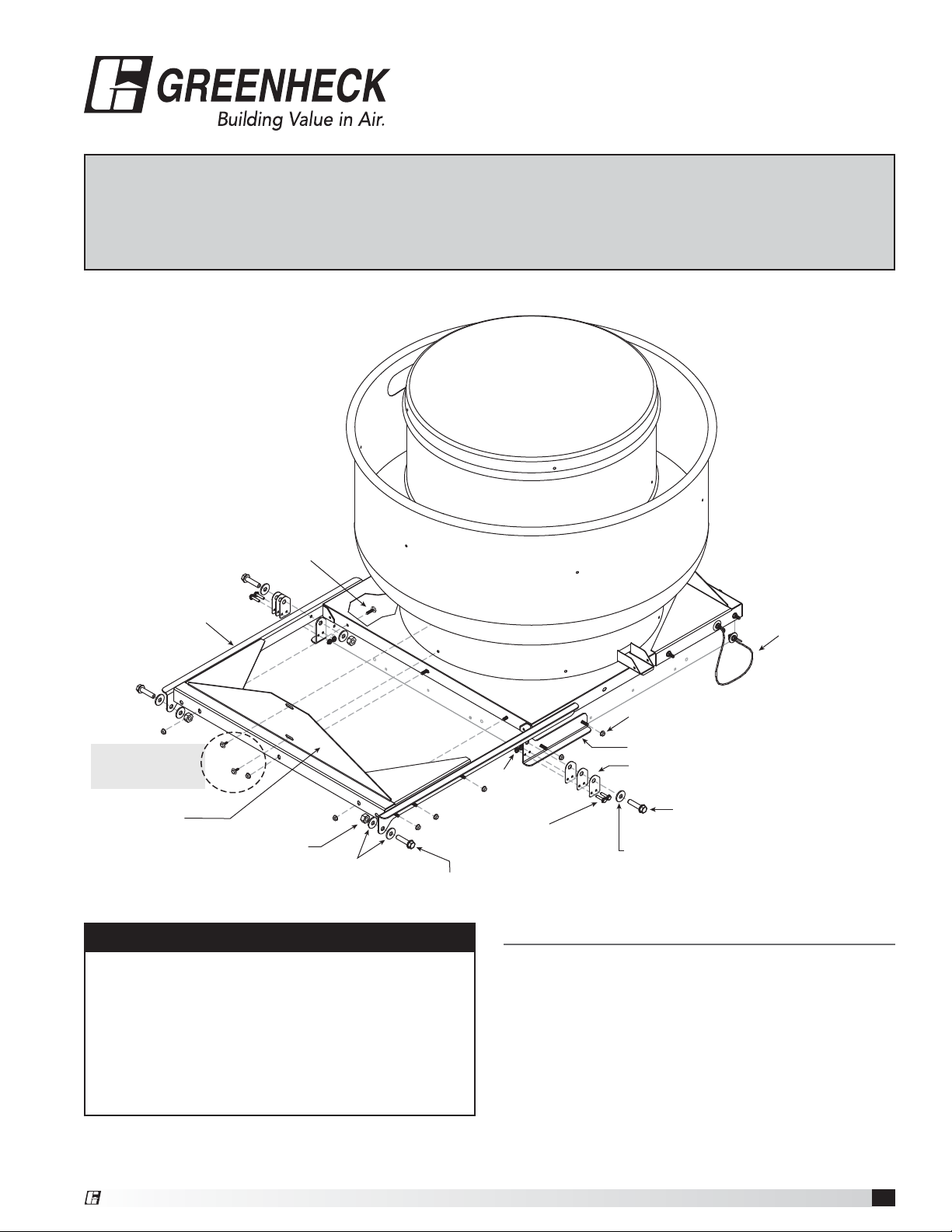
FIGURE 1
Fan
Weld Bolt
5/16-18 x 1
Top Hinge
Step 1:
Remove from fan
unit and reuse
Reinforcing
Assembly Plate
Nut 1/2-13
Nylock
Flat Washer
1/2 x 1-1/16
Bolt 1/2-13 x 2
WARNING
Disconnect power and observe proper lock out tag
out procedures per OSHA regulation (Title 29 code of
federal regulations part 1910.147 & 1910.333).
Note: If fan is connected to electrical source via rigid
connection, a qualified electrician will need to change
the rigid connection to a flexible connection long
enough per local electrical codes to allow for fan
movement.
Restraining
Cable
Curb Cap
Nut 5/16-18
Bottom Hinge
Nut
1/4-20
Hinge Spacer(s)
Bolt 1/2-13 x 2
Bolt
1/4 x 20 x 1¼
Flat Washer
1/2 x 1-1/16
Installation
1. Step 1, remove bolts/screws from fan unit that will
be used to connect the reinforcing assembly plate.
FIGURE 1.
If fan is currently installed on a curb, remove screws
holding the cap to the curb. If this does not apply
go to Step 2.
®
Hinge Kit
1
Page 2
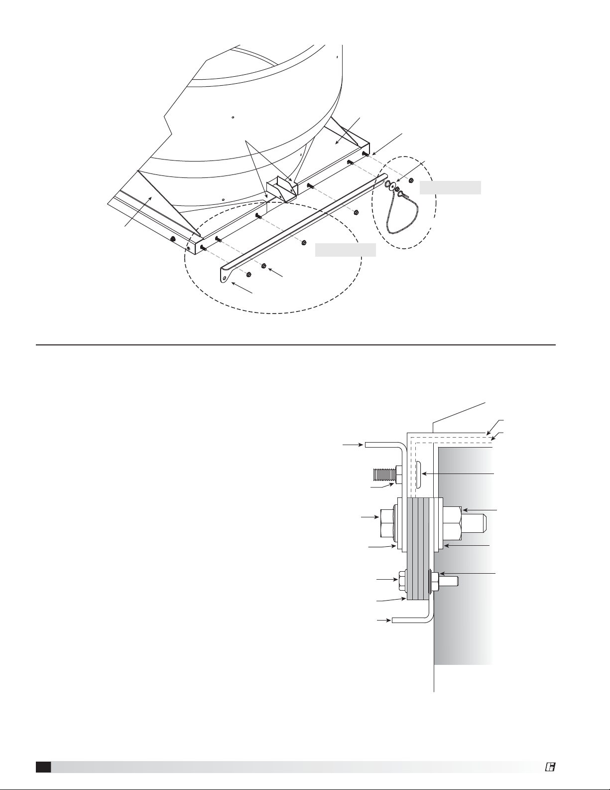
FIGURE 2
Curb Cap
Reinforcing
Assembly
Plate
Weld Bolt
5/16-18 x 1
Fender Washer
5/16-18 x 1
Step 4
Reinforcing
Assembly
Plate
Top Hinge
2. Place reinforcing assembly on the curb cap; loosely
install the four screws removed in Step 1.
If cap has factory holes that line up with hinge
holes, go to Step 3. If cap does not have matching
holes from the factory, mark the remaining hole
locations for drilling. Drill a 5/16 inch hole in the
curb cap at these locations.
3. Attach each top hinge and reinforcing assembly to
the curb cap with 5/16 inch - 18 x 1 inch long weldbolt screws and 5/16 inch spinlock nuts. Refer to
FIGURE 2.
NOTE: The stop cable is installed to the top hinge
under the nut furthest from the pivot point. Secure
the cable with the 5/16 inch x 1-1/4 inch fender
washer. Allow the opposite end to hang loose until
Step 8. FIGURE 2
4. Set unit on roof curb or hinge base. Center curb cap
on the curb or hinge base so there is equal space
around the perimeter. If curb cap has a hinge base,
align hold down screws with threaded holes and
loosely install thumb screws.
Refer to FIGURE 4.
5. Attach each lower hinge to the upper hinge with
the 1/2 inch - 13 x 2 inch bolt, 1/2 inch washers
and 1/2inch nylock nut. Attach equal number of
hinge spacers to bottom hinge with 1/4 inch - 20 x
1-1/4inch bolts and 1/4 inch nut to take up the gap
between the top and bottom hinges. THE NUMBER
OF SPACERS WILL VARY FROM UNIT TO UNIT.
Refer to FIGURE 3.
Steps 2 and 3
Nut 5/16-18
FIGURE 3 - Reinforcing Assembly
Top
Hinge
Nut 5/16-18
Bolt
1/2-13 x 2
Flat Washer
1/2 x 1-1/16
Bolt
1/4 x 20 x 1¼
Hinge Spacer
Bottom Hinge
Restaining CableRestaining Cable
Fan Curb
Cap
Hinge
Frame
Weld Bolt
5/16-18 x 1
Nut 1/2-13
Flat Washer
1/2 x 1-1/16
Nut 1/4-20
Inside of curb
2
Hinge Kit
®
Page 3

6. Rotate the lower hinge
until parallel with the upper
hinge. If cap has factory
holes that line up with hinge
holes, go to Step 7. If cap
does not have matching
holes from the factory,
mark the hole locations in
the curb and drill a 5/16
inch hole at each location.
Reference FIGURE 4.
FIGURE 4
Stop Cables
Thumb
Screws
Fan
Steps 6 and 7
Upper Hinge
Pivot Bolt
Lower Hinge
Optional
Hinge Base
Roof Curb
CAUTION
Roof curb or extended base should be properly
attached to the roof to support the fan and curb when
moved to the open position.
7. Install 5/16 inch weld bolts through lower hinge
into curb and install nuts. If necessary, disconnect
hinge bolt and remove unit from curb to install lower
hinge.
NOTE: If curb is of construction other than sheet
metal, use appropriate connector. For example,
if the curb is made of wood, use a lag bolt.
8. Attach the loose end of the stop cable to the curb
with appropriate fastener and fender washer.
See FIGURE 5 for hole location.
9. Wind gusts are capable of lifting the curb cap off
from the curb. Secure the curb cap to the curb
with the thumb screws provided with a hinge base
or other appropriate method.
FIGURE 5
Dimension A Model
8 inches 200 - 480
16 inches 500 - 540
A
4 inches
(101.6 mm)
Step 8
®
Hinge Kit
3
Page 4

G/GB Replacement Parts
Item
No.
1 Reinforcing Assembly 822348 829561 830873 830874 830875 868633
2 Hinge, Galvanized, Top, Left 742407 742410 742417 742413 742414 742415
3 Hinge, Galvanized, Top, Right 742448 742450 742578 742617 742669 742724
4 Hinge, Galvanized, Bottom, Left 742416 742412 742418 742419 742420 742421
5 Hinge, Galvanized, Bottom, Right 742449 742451 742579 742629 742670 742725
Description
Model No.
Length (inches) 34 40 46 52 58 64
220-240 260-300 330-360 420 480 500-540
CUE/CUBE Replacement Parts
Item
No.
1 Reinforcing Assembly 817129 817130 817133 817131 817132 N/A
2 Hinge, Galvanized, Top, Left 742407 742410 742417 742413 742414 742415
3 Hinge, Galvanized, Top, Right 742448 742450 742578 742617 742669 742724
4 Hinge, Galvanized, Bottom, Left 742416 742412 742418 742419 742420 742421
5 Hinge, Galvanized, Bottom, Right 742449 742451 742579 742629 742670 742725
Description
Model No.
Length (inches) 34 40 46 52 58 64
220-240 300 360 420 480 N/A
4
3
1
5
3
Our Commitment
As a result of our commitment to continuous improvement, Greenheck reserves the right to change specifications
without notice.
Specific Greenheck product warranties are located on greenheck.com within the product area tabs and in the
Library under Warranties.
®
Phone: 715.359.6171 • Fax: 715.355.2399 • Parts: 800.355.5354 • E-mail: gfcinfo@greenheck.com • Website: www.greenheck.com
462865 • Hinge Kit, Rev. 2, July 2013 Copyright 2013 © Greenheck Fan Corporation
4
 Loading...