


Greenheck Fan 455924 ERV-251, 455924 ERV-521, 455924 ERV-361, 455924 ERV-582, 455924 ERV-581 User Manual
...Part #455924
® |
Energy Recovery Ventilators |
|
Installation, Operation and Maintenance Manual
Please read and save these instructions. Read carefully before attempting to assemble, install, operate or maintain the product described. Protect yourself and others by observing all safety information. Failure to comply with instructions could result in personal injury and/or property damage! Retain instructions for future reference.
Models: ERV-251
ERV-361
ERV-521
ERV-581
ERV-522
ERV-582
General Safety Information
Only qualified personnel should install this system. Personnel should have a clear understanding of these instructions and should be aware of general safety precautions. Improper installation can result in electric shock, possible injury due to coming in contact with moving parts, as well as other potential hazards. Other considerations may be required if high winds or seismic activity are present. If more information
is needed, contact a licensed professional engineer before moving forward.
DANGER
Always disconnect power before working on or near this equipment. Lock and tag the disconnect switch or breaker to prevent accidental power up.
CAUTION
When servicing the unit, the internal components may be hot enough to cause pain or injury. Allow time for cooling before servicing.
CAUTION
Precaution should be taken in explosive atmospheres.
1 Model ERV Energy Recovery Unit
1.Follow all local electrical and safety codes, as well as the National Electrical Code (NEC), the National Fire Protection Agency (NFPA), where applicable.
Follow the Canadian Electric Code (CEC) in Canada.
2.All moving parts must be free to rotate without striking or rubbing any stationary objects.
3.Unit must be securely and adequately grounded.
4.Do not spin fan wheel faster than maximum cataloged fan RPM. Adjustments to fan speed significantly effects motor load. If the fan RPM is changed, the motor current should be checked to make sure it is not exceeding the motor nameplate amps.
5.Do not allow the power cable to kink or come in contact with oil, grease, hot surfaces or chemicals. Replace cord immediately if damaged.
6.Verify that the power source is compatible with the equipment.
7.Never open access doors to the unit while it is running.

Receiving
Upon receiving the product, check to make sure all items are accounted for by referencing the bill of lading to ensure all items were received. Inspect each crate for shipping damage before accepting delivery. Notify the carrier if any damage is noticed. The carrier will make notification on the delivery receipt acknowledging any damage to the product. All damage should be noted on all the copies of the bill of lading which is countersigned by the
delivering carrier. A Carrier Inspection Report should be filled out by the carrier upon arrival and the Traffic Department. If damaged upon arrival, file claim
with carrier. Any physical damage to the unit after acceptance is not the responsibility of Greenheck Fan Corporation.
Unpacking
Verify that all required parts and the correct quantity of each item have been received. If any items are missing report shortages to your local representative to arrange for obtaining missing parts. Sometimes it is not possible that all items for the unit be shipped together due to availability of transportation and truck space. Confirmation of shipment(s) must be limited to only items on the bill of lading.
Handling
Units are to be rigged and moved by the lifting brackets provided or by the skid when a forklift is used. Location of brackets varies by model and size. Handle each piece in such a manner as to keep from scratching or chipping the coating. Damaged finish may reduce ability of the unit to resist corrosion.
Storage
Units are protected against damage during shipment. If the unit cannot be installed and operated immediately, precautions need to be taken to prevent deterioration of the unit during storage. The user assumes responsibility of the unit and accessories while in storage. The manufacturer will not be responsible for damage during storage. These suggestions are provided solely as a convenience to the user.
Inspection and Maintenance during Storage
While in storage, inspect units once per month. Keep a record of inspection and maintenance performed
If moisture or dirt accumulations are found on parts, the source should be located and eliminated. At each inspection, rotate all moving components by hand ten to fifteen revolutions to distribute lubricant on motor and bearings. If paint deterioration begins, consideration should be given to touch-up or repainting. Units with special coatings may require special techniques for touch-up or repair.
Machined parts coated with rust preventive should be restored to good condition promptly if signs of rust occur. Immediately remove the original rust preventive coating with petroleum solvent and clean with lint-free cloths. Polish any remaining rust from surface with crocus cloth or fine emery paper and oil. Do not destroy the continuity of the surfaces. Wipe clean thoroughly with Tectyl® 506 (Ashland Inc.) or the equivalent. For hard to reach internal surfaces or for occasional use, consider using Tectyl® 511M Rust Preventive or WD-40® or the equivalent.
2 Model ERV Energy Recovery Unit
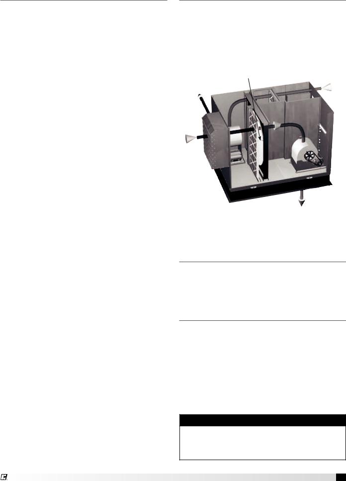
Table of Contents
Basic Operation |
|
|
|
|
3 |
Installation |
|
|
|
|
|
Supplemental Installation, Operation and |
|
|
|
|
|
Maintenance Manuals |
|
|
|
|
3 |
Installation Concerns . . . . . . . . |
. |
. |
. |
3 |
|
Lifting |
|
|
|
|
4 |
Roof Curb and Rail Mounting |
|
|
|
|
|
Recommended Roof Opening |
|
|
|
|
4 |
Roof Curb Mounting |
|
|
|
|
5 |
Curb Dimensions and Weights . . . . |
. |
. |
. |
5 |
|
Ductwork Connections |
|
|
|
|
5 |
Rail Mounting / Layout |
|
|
|
|
6 |
Service Clearances . . . . . . . . . |
. |
. |
. |
7 |
|
Electrical Information |
|
|
|
|
|
General Electrical Information |
|
|
|
|
8 |
Control Center Components . . . . . |
. |
. |
. |
9 |
|
Electric Heater Application/Operation . |
. |
. |
. |
9 |
|
Unit Accessories . . . . . . . . . . |
. |
. |
. |
9 |
|
Access Panel Description and Location |
. . 10-11 |
||||
Dimensional Data |
|
|
|
12-13 |
|
Optional Accessories |
|
|
|
|
|
Frost Control Application/Operation . . |
. |
. |
. 14 |
||
Economizer Application/Operation |
|
|
|
|
15 |
Variable Frequency Drives and Wiring . |
. . 16-17 |
||||
Typical Wiring Diagram . . . . . . . |
. |
. |
. 18 |
||
Sensors and Lights . . . . . . . . . |
. |
. |
. 19 |
||
Remote Control Panel and Wiring . . . |
. |
. |
. 20 |
||
Sensors Mounted by Factory . . . . . |
. |
. |
. 21 |
||
Sequence of Operation |
|
|
|
|
|
Start-Up |
|
|
|
|
|
Unit . . . . . . . . . . . . . . . |
. |
. |
. |
22 |
|
Optional Accessories . . . . . . . . |
. |
. |
. 23 |
||
Fan |
|
|
|
|
24 |
Energy Recovery Wheel . . . . . . . |
. |
. |
. 25 |
||
Routine Maintenance Checklist |
|
|
|
|
|
General |
|
|
|
|
26 |
Fan Belts . . . . . . . . . . . . . |
. |
. |
. 26 |
||
Fan Motors . . . . . . . . . . . . |
. |
. |
. 26 |
||
Fan Wheel and Fasteners |
|
|
|
|
27 |
Fan Bearings |
|
|
|
|
27 |
Filters |
|
|
|
|
27 |
Door Seal Maintenance . . . . . . . |
. |
. |
. 27 |
||
Energy Recovery Wheel Maintenance |
|
|
|
|
|
Accessing Energy Recovery Wheel |
|
|
|
27-28 |
|
Removing Wheel Segments |
|
|
|
|
28 |
Cleaning Wheel Segments . . . . . |
. |
. |
. 29 |
||
Wheel Belt |
|
|
|
|
29 |
Wheel Bearing . . . . . . . . . . |
. |
. |
. 29 |
||
Parts List |
|
|
|
|
30 |
Sequence of Operation . . . . . . . |
. |
. |
. |
31 |
|
Troubleshooting – Airflow . . . . . . |
. |
. |
. |
32 |
|
Troubleshooting – Unit |
|
|
33-34 |
||
Maintenance Log . . . . . . . . . . |
. |
. |
. |
35 |
|
Warranty |
Backcover |
||||
Basic Operation
The ERV brings in fresh, outdoor air and removes stale, exhaust air. Prior to discharging the exhaust air, the energy recovery wheel transfers energy from the exhaust air to the outdoor air at an efficiency
of 70-80%. Simply put, this unit preconditions the outdoor air to save money on heating and cooling costs.
|
Energy Recovery |
Exhaust air |
Exhaust air |
Wheel |
from building |
discharged |
|
|
outside |
|
|
Outdoor
air
Preconditioned air sent to space
Supplemental Installation,
Operation and Maintenance
Manuals
Refer to the following Installation, Operation and Maintenance Manuals for additional details:
Part #460988 — ERV-522 and ERV-582 Curbs Part #462844 — ERV Exhaust Weatherhood
Installation
The system design and installation should follow accepted industry practice, such as described in the ASHRAE Handbook.
Adequate space should be left around the unit for filter replacement and maintenance. Sufficient space should be provided on the side of the unit for routine service and component removal should that become necessary.
See Service Clearances and Access Panel Description sections for more details.
Warning
All factory provided lifting lugs must be used when lifting the unit. Failure to comply with this safety precaution could result in property damage, serious injury or death.
Model ERV Energy Recovery Unit 3
Lifting
1.Before lifting, be sure that all shipping material has been removed from unit.
2.To assist in determining rigging requirements, weights are shown below.
3.Unit must be lifted by all lifting lugs provided on base structure.
4.Rigger to use suitable mating hardware to attach to unit lifting lugs.
5.Spreader bar(s) must span the unit to prevent damage to the cabinet by the lift cables.
6.Always test-lift the unit to check for proper balance and rigging before hoisting to desired location.
7.Never lift units by weatherhoods.
8.Never lift units in windy conditions.
9.Preparation of curb and roof openings should be completed prior to lifting unit to the roof.
10.Check to be sure that gasketing has been applied to the curb prior to lifting the unit and setting on curb.
11.Do not use fork lifts for handling unit.
|
Unit Weights |
|
Unit Size |
|
Approx. Weight (lbs)* |
|
|
|
ERV-251 |
|
340 |
|
|
|
ERV-361 |
|
860 |
|
|
|
ERV-521 |
|
1290 |
|
|
|
ERV-581 |
|
1470 |
|
|
|
ERV-522 |
|
3230 |
|
|
|
ERV-582 |
|
3700 |
|
|
|
*Weight assumes outdoor unit with filters, weatherhoods and outdoor air intake damper.
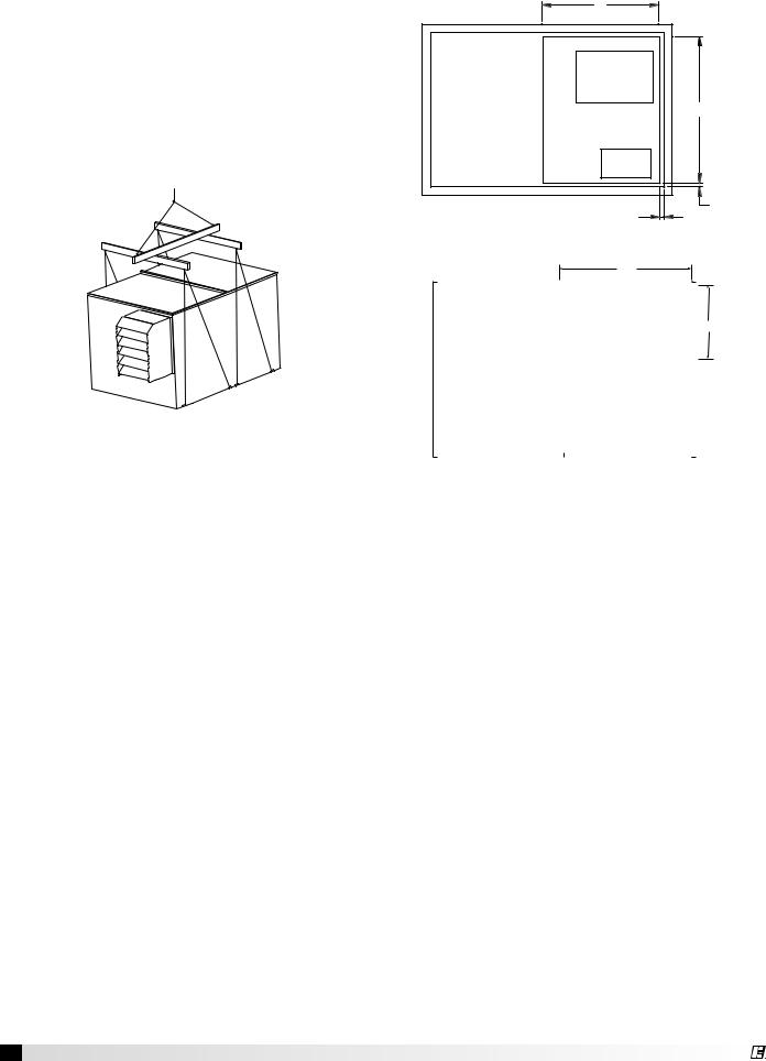
Recommended Roof Opening
V
EXHAUST
INTAKE
U
SUPPLY
DISCHARGE
0.50
0.50
ERV-251, 361, 521 and 581
U
|
EXHAUST |
|
|
|
|
|
|
|
INLET |
SUPPLY DISCHARGE |
V |
|
|
|
|
|
|
|
|
|
|
|
|
|
|
|
|
ERV-522 and 582
Position the unit roof
opening such that the supply discharge and exhaust inlet of the unit will line up with the corresponding ductwork. Be sure
to allow for the recommended service
Unit Size |
U |
V |
|
|
|
ERV-251 |
26.5 |
20 |
|
|
|
ERV-361 |
43 |
26 |
|
|
|
ERV-521 |
58 |
35 |
|
|
|
ERV-581 |
60 |
30 |
|
|
|
ERV-522 |
62 |
36 |
|
|
|
ERV-582 |
77 |
38 |
|
|
|
clearances when positioning opening
(see Service Clearances). Do not face the outdoor air intake of the unit into prevailing wind and keep the intake away from any other exhaust fans. Likewise, position the exhaust discharge opening away from outdoor air intakes of any other equipment.
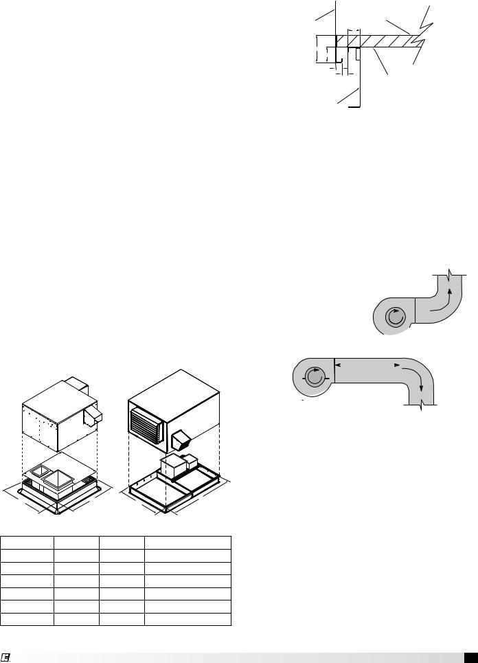
When cutting only duct openings, cut opening 1 inch (25mm) larger than duct size to allow clearance for installation. Area enclosed by roof curb must comply with clearance to combustible materials. If the roof is constructed of combustible materials, area within the roof curb must be ventilated, left open, or covered with non-combustible material which has an “R” value of at least 5. If area within curb is open, higher radiated sound levels may result.
Where the supply or warm air duct passes thru a combustible roof, a clearance of one inch must be maintained between the outside edges of the duct and combustible material in accordance with NFPA Standard 90A.
4 Model ERV Energy Recovery Unit
Roof Curb Mounting
Roof curb details including duct location dimensions, are available on ERV-522 & 582 Roof Curb Assembly Instructions, Part #460988.
Rooftop units require curbs to be mounted first. The duct connections must be located so they will be clear of structural members of the building.
1.Factory Supplied Roof Curbs: Roof curbs are Model GPI or GPNS for the ERV-251, 361, 521, 581. The GPI or GPNS ships assembled and includes a duct adapter.
Roof curbs are Model GKD for the ERV-522 and 582. The GKD ships in a knockdown kit (includes duct adapter) and requires field assembly (by others). Assembly instructions are included with the GKD curbs.
2.Install Curb: Locate curb over roof opening and fasten in place. (Refer to Recommended Roof Openings). Check that the diagonal dimensions are within ±1/8 inch of each other and adjust
as necessary. For proper unit operation, it is important that the installation be level. Shim as required to level.
3.Install Ductwork: Installation of all ducts should be done in accordance with SMACNA and AMCA guidelines. Duct adapter provided to support ducts prior to setting the unit.
4.Set the Unit: Lift unit to a point directly above the curb and duct openings. Guide unit while lowering to align with duct openings. Roof curbs fit inside the unit base. Make sure the unit is properly seated on the curb and is level.
Curb Outside Dimensions and Weights
W |
|
L |
L |
|
W |
||
ERV-251, 361, 521 and 581 |
ERV-522 and 582 |
||
Unit Size |
L |
W |
Curb Weight (lbs.) |
ERV-251 |
42.5 |
30.5 |
60 |
ERV-361 |
58.5 |
47.5 |
115 |
ERV-521 |
63.5 |
63.5 |
160 |
ERV-581 |
71.8 |
66 |
185 |
ERV-522 |
120.5 |
80.5 |
520 |
ERV-582 |
142.25 |
93 |
700 |
All dimensions are in inches. Weights are for 12-inch high GPI type curbs.
Curb Outside Dimensions - continued
Side of Unit |
|
Base |
|
|
|
|
|
A |
|
B |
|
|
C |
|
|
D |
|
|
E |
1-inch Insulation |
|
|
Roof Curb
Curb Cap Details for Factory Supplied Roof Curbs
Unit Size |
A |
B |
C |
D |
E |
|
|
|
|
|
|
ERV-251 |
1.75 |
2.00 |
1.00 |
1.125 |
0.750 |
|
|
|
|
|
|
ERV-361 |
1.75 |
2.00 |
1.00 |
1.200 |
0.875 |
|
|
|
|
|
|
ERV-521 |
1.75 |
2.00 |
1.00 |
0.813 |
0.875 |
|
|
|
|
|
|
ERV-581 |
1.75 |
2.00 |
1.00 |
0.813 |
0.750 |
|
|
|
|
|
|
ERV-522 |
1.813 |
4.00 |
1.75 |
1.000 |
0.750 |
|
|
|
|
|
|
ERV-582 |
1.938 |
4.125 |
1.938 |
1.125 |
0.625 |
|
|
|
|
|
|
All dimensions are in inches.
Ductwork Connections
Examples of poor and good fan-to-duct connections are shown. Airflow out of the fan should
be directed straight or curve |
|
|
|
|
|
|
|
|
|
|
|
|||||||||||||
same direction as the |
|
|
|
|
|
|
|
|
|
|
|
|
|
|
|
|||||||||
fan wheel rotates. Poor |
|
|
|
|
||||||||||||||||||||
|
|
tion |
|
|
||||||||||||||||||||
|
|
|
|
|
|
|
|
|
|
|
|
|
|
|
a |
|
|
|||||||
|
|
|
|
|
|
|
|
|
|
|
|
|
|
t |
|
|
|
|
|
|
|
|
|
|
duct installation will |
|
|
|
R |
o |
|
|
|
|
|
|
|
|
|
|
|||||||||
|
|
|
|
|
|
|
|
|
|
|
|
|
|
|||||||||||
|
|
|
|
|
|
|
|
|
|
|
|
|
|
|
||||||||||
result in low airflow and |
|
|
|
|
|
|
|
|
|
|
|
|
||||||||||||
|
|
|
|
|
|
|
|
|
|
|
|
|||||||||||||
|
|
|
|
|
|
|
|
|
|
|
|
|||||||||||||
other system effects. |
|
|
|
|
|
|
|
|
|
|
|
POOR |
||||||||||||
|
|
|
|
|
|
tion |
|
|
|
|
|
|
|
|
|
|
|
|
|
|
|
|
|
|
|
|
|
|
|
|
|
|
|
|
|
|
|
|
|
|
|
|
|
|
|
|
|
||
|
|
|
|
|
|
|
Length of Straight Duct |
|
|
|
|
|
|
|||||||||||
|
|
|
|
|
a |
|
|
|
|
|
|
|||||||||||||
|
|
|
|
t |
|
|
|
|
|
|
|
|
|
|||||||||||
|
|
|
R |
o |
|
|
|
|
|
|
|
|
|
|
|
|
|
|
|
|
|
|
|
|
|
|
|
|
|
|
|
|
|
|
|
|
|
|
|
|
|
|
|
|
|
|
|
|
|
|
|
|
|
|
|
|
|
GOOD |
|
|
|
|
|
|
|
|
|
|
|
|||||
|
|
|
|
|
|
|
|
|
|
|
|
|
|
|
|
|
|
|
||||||
|
|
|
|
|
|
|
|
|
|
|
|
|
|
|
|
|
|
|
||||||
|
|
|
|
|
|
|
|
|
|
|
|
|
|
|
|
|
|
|
||||||
|
|
|
|
|
|
|
|
|
|
|
||||||||||||||
Recommended Discharge Duct Size and Length |
||||||||||||||||||||||||
Model |
Blower Size |
|
Duct Size |
|
Straight Duct Length |
|||||||||||||||||||
|
|
|
|
|
|
|
|
|
|
|
|
|
|
|
|
|
|
|
|
|
||||
ERV-251 |
|
|
|
|
10 |
|
|
|
|
9 x 9 |
|
|
|
36 |
|
|||||||||
|
|
|
|
|
|
|
|
|
|
|
|
|
|
|
|
|
|
|
|
|
||||
ERV-361 |
|
|
|
|
10 |
|
|
|
|
14 x 14 |
|
|
|
36 |
|
|||||||||
|
|
|
|
|
|
|
|
|
|
|
|
|
|
|
|
|
|
|
|
|
||||
ERV-521 |
|
|
|
|
12 |
|
|
|
|
20 x 20 |
|
|
|
36 |
|
|||||||||
|
|
|
|
|
|
|
|
|
|
|
|
|
|
|
|
|
|
|
|
|
||||
ERV-581 |
|
|
|
|
15 |
|
|
|
|
28 x 28 |
|
|
|
60 |
|
|||||||||
|
|
|
|
|
|
|
|
|
|
|
|
|
|
|
|
|
|
|
|
|
||||
ERV-522S |
|
|
|
|
15 |
|
|
|
|
28 x 28 |
|
|
|
60 |
|
|||||||||
|
|
|
|
|
|
|
|
|
|
|
|
|
|
|
|
|
|
|
|
|
||||
ERV-522H |
|
|
|
|
18 |
|
|
|
|
32 x 32 |
|
|
|
60 |
|
|||||||||
|
|
|
|
|
|
|
|
|
|
|
|
|
|
|
|
|
|
|
|
|
||||
ERV-582 |
|
|
|
|
20 |
|
|
|
|
34 x 34 |
|
|
|
72 |
|
|||||||||
|
|
|
|
|
|
|
|
|
|
|
|
|
|
|
|
|
|
|
|
|
|
|
|
|
All dimensions shown in inches.
•Recommended duct sizes are based on velocities across the cfm range of each model at approximately 800 feet per minute (FPM) at minimum airflow and up to 1600 fpm at maximum airflow. Recommended duct sizes are only intended to be a guide and may not satisfy the requirements of the project. Refer to plans for appropriate job specific duct size and/or velocity limitations.
•Straight duct lengths were calculated based on 100% effective duct length requirements as prescribed in AMCA Publication 201. Calculated values have been rounded up to nearest foot.
Model ERV Energy Recovery Unit 5
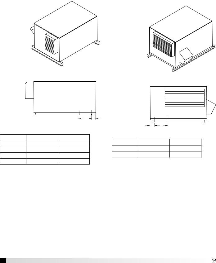
Rail Mounting / Layout
•Rails designed to handle the weight of the ERV should be positioned as shown on the diagram (rails by others).
•Make sure that rail positioning does not interfere with the supply air discharge opening or the exhaust air intake opening on the ERV unit. Avoid area dimensioned “B” below.
•Rails should extend beyond the unit a minimum of 12 inches on each side.
•Set unit on rails.
ERV-251 ERV-361 ERV-521 ERV-581
ERV-522 ERV-582
|
|
E |
|
AIR |
SID |
OUTDOOR |
|
|
|
|
Isometric view of
ERV on rails
OUTDOORA |
|
IR |
|
INT |
|
AKE |
END |
|
Isometric view of
ERV on rails
OUTDOOR |
|
|
AIR |
|
|
INTAKE |
|
OUTDOOR AIR SIDE |
HOOD |
|
|
|
|
SUPPLY/EXHAUST |
|
|
OPENING |
Side view of |
|
B A |
ERV on rails |
|
|
|
|
|
Unit Size |
A |
B |
ERV-251 |
4.50 |
16 |
ERV-361 |
4.75 |
18 |
ERV-521 |
5.75 |
24 |
ERV-581 |
4.875 |
22 |
All dimensions are in inches.
OUTDOOR AIR INTAKE HOOD
|
|
OUTDOOR AIR INTAKE END |
|
SUPPLY/EXHAUST |
|
|
OPENING |
|
Side view of |
|
|
ERV on rails |
A |
B |
Unit Size |
A |
B |
ERV-522 |
4.625 |
32 |
ERV-582 |
4.875 |
33.25 |
All dimensions are in inches.
6 Model ERV Energy Recovery Unit
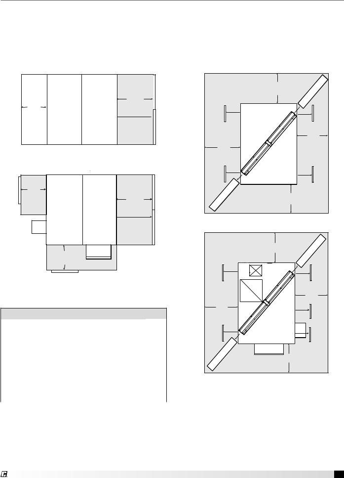
Service Clearances
ERV-251, 361, 521 and 581 units require minimum clearances to perform routine maintenance, such as filter replacement, energy wheel cassette inspection, and fan belt adjustment. Blower and motor assemblies, energy recovery wheel cassette and filter sections are always provided with a service door or panel for proper component access. Clearances for component removal may be greater than the service clearances, refer to drawings below for these dimensions.
ERV-251, ERV-361, ERV-521, ERV-581
Access |
T |
Exhaust |
Outdoor |
|
|
Side |
Air Side |
Panels |
|
||
|
|
|
|
|
|
|
|
|
|
|
|
*ERV-251, 361, and 521 only.
Arrangement A
R
Cassette slides out*
 Access Panels
Access |
T |
|
|
Panels |
Panel |
|
|
R |
|
|
|
|
|
|
|
Exhaust |
Outdoor |
|
Access |
|
Side |
Air Side |
Cassette slides out* |
|
|
|
|||
|
Exhaust |
|
|
|
|
Hood |
|
|
|
Intake Hood
S
Access Panel
*ERV-251, 361, and 521 only.
Arrangement B, C or D
Recommended Service Clearances
Unit Size |
R |
S |
T |
X |
|
|
|
|
|
ERV-251 |
32 |
30 |
30 |
|
|
|
|
|
|
ERV-361 |
44 |
30 |
30 |
|
(30 for maintenance) |
|
|||
|
|
|
|
|
ERV-521 |
60 |
40 |
40 |
|
(39 for maintenance) |
|
|||
|
|
|
|
|
ERV-581 |
65 |
40 |
40 |
|
(32 for maintenance) |
|
|||
|
|
|
|
|
ERV-522 |
|
|
|
38 |
|
|
|
|
|
ERV-582 |
|
|
|
42 |
|
|
|
|
|
All dimensions are in inches.
ERV-522, ERV-582 |
|
|
|
X |
Cassette |
|
|
|
Panel Access |
|
Access Panel |
|
|
X |
X |
|
|
Panel Access |
|
Access Panel |
Cassette |
|
X |
Arrangement A
|
X |
Cassette |
|
|
|
Panel Access |
|
Access Panel |
|
|
X |
X |
|
Panel |
|
|
Access |
Panel Access |
|
Access Panel |
|
|
Exhaust |
|
|
Weatherhood |
Cassette |
Supply |
X |
Weatherhood |
Arrangement B, C or D
Model ERV Energy Recovery Unit 7

Electrical Information
The unit must be electrically grounded in accordance with the current National Electrical Code, ANSI/NFPA 70. In Canada, use current CSA Standard C22.1, Canadian Electrical Code, Part 1. In addition, the installer should be aware of any local ordinances or electrical company requirements that might apply. System power wiring must be properly fused and conform to the local and national electrical codes. System power wiring is to the unit main disconnect (door interlocking disconnect switch standard
on most units) or distribution block and must be compatible with the ratings on the nameplate: supply power voltage, phase, and amperage (Minimum Circuit Amps - MCA, Maximum Overcurrent Protection - MOP). All wiring beyond this point has been done by the manufacturer and cannot be modified without affecting the unit’s agency / safety certification.
If field installing an additional disconnect switch, it is recommended that there is at least four feet of service room between the switch and system access
panels. When providing or replacing fuses in a fusible disconnect, use dual element time delay fuses and size according to the rating plate.
If power supply is desired through bottom of unit, run the wiring through the curb, cut a hole in the cabinet bottom, and wire to the disconnect switch. Seal penetration in cabinet bottom to prevent leakage.
The electric supply to the unit must meet stringent requirements for the system to operate properly. Voltage supply and voltage imbalance between phases should be within the following tolerances. If the power is not within these voltage tolerances, contact the power company prior to operating the system.
Voltage Supply: See voltage use range on the rating plate. Measure and record each supply leg voltage at all line disconnect switches. Readings must fall within the allowable range on the rating plate.
Voltage Imbalance: In a 3-phase system, excessive voltage imbalance between phases will cause motors to overheat and eventually fail. Maximum allowable imbalance is 2%. To determine voltage imbalance, use recorded voltage measurements in this formula.
Key: V1, V2, V3 = line voltages as measured VA (average) = (V1 + V2 + V3) / 3
VD = Line voltage (V1, V2 or V3) that deviates farthest from average (VA)
Formula: % Voltage Imbalance = [100 x (VA-VD)] / VA
CAUTION
If any of the original wire as supplied with the appliance must be replaced, it must be replaced with wiring material having a temperature rating of at least 105ºC.
8 Model ERV Energy Recovery Unit
WARNING
To prevent injury or death due to electrocution or contact with moving parts, lock disconnect switch open.
Most factory supplied electrical components are prewired. To determine what electrical accessories require additional field wiring, refer to the unit specific wiring diagram located on the inside of the unit control center access door. The low voltage control circuit is 24 VAC and control wiring should not exceed 0.75 ohms.
Refer to Field Control Wiring Length/Gauge table for wire length maximums for a given wire gauge.
Field Control Wiring Length/Gauge
Total |
Minimum |
Wire Length |
Wire Gauge |
125 ft. |
18 |
200 ft. |
16 |
300 ft. |
14 |
450 ft. |
12 |
Control wires should not be run inside the same conduit as that carrying the supply power. Make sure that field supplied conduit does not interfere with access panel operation.
If wire resistance exceeds 0.75 ohms, an industrialstyle, plug-in relay should be added to the unit control center and wired in place of the remote switch (typically between terminal blocks R and G on the terminal strip (refer to Typical Control Center Components). The relay must be rated for at least 5 amps and have a 24 VAC coil. Failure to comply with these guidelines may cause motor starters to “chatter” or not pull in which can cause contactor failures and/or motor failures.
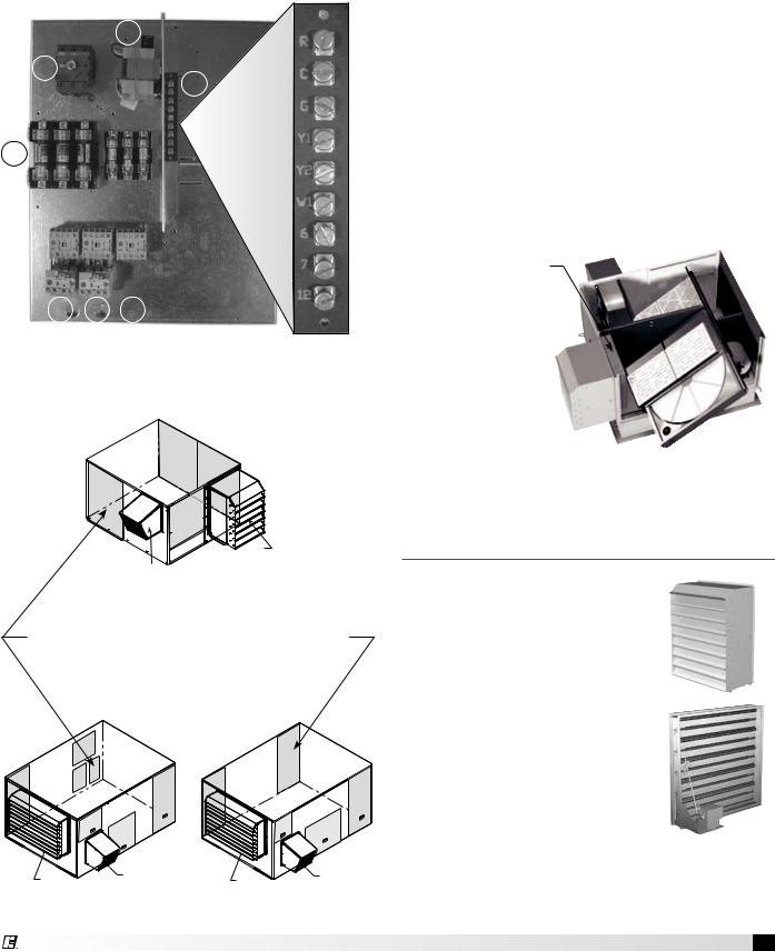
Typical Control Center Components
1.Main Disconnect (non-fusible, lockable)
2.Motor Starter – Exhaust Air Fan
3.Motor Starter – Outdoor Air Fan
4.Motor Contactor – Energy Wheel
5.24 VAC Control Transformer
6.24 VAC Terminal strip
7.Fuses for blower motors
5
1
6
7
2 3 4
Exploded Detail
of Terminal Strip
ERV-251, 361, 521, 581
Intake
Hood
Exhaust
Hood
Access to Control Center Components
is gained through the access panel indicated.
ERV-522 |
ERV-582 |
Intake |
Exhaust Hood |
Intake |
Exhaust Hood |
|
|||
Hood |
|
Hood |
|
Electric Heater Application/Operation
Factory installed electric heaters can be provided for preheat frost control. An electric preheater warms the outdoor air prior to the energy recovery wheel to prevent frosting on the wheel. Electric heaters are available in 208, 230, or 460 VAC (refer to heater nameplate for voltage).
Preheaters: Preheaters are standard as 2-stage, step control. Step control heaters are designed with multiple stages made up of equal increments of heating capability. For example, a 10 kW heater with two stages will be composed of two 5-kW stages. Preheaters are single point wired at the factory.
A temperature sensor (with field adjustable set point) is mounted in the outdoor airstream after the preheater to turn the preheater on. See Frost Control Application/Operation for typical set points. If the temperature falls below the set point and the wheel pressure drop sensor is triggered, the first stage of the preheater will turn on. If the first stage does not satisfy the set point, the second stage will also turn on.
Electric Preheater:
The preheater is single point wired to the unit control center. Access to
the preheater control panel is through
the outdoor air filter door.
Unit Accessories
Outdoor Air Weatherhood
Outdoor air weatherhood will be factory mounted.
Exhaust Weatherhood
The exhaust weatherhood is shipped separately as a kit with its own instructions.
Dampers
Backdraft dampers are always included as an integral part of the exhaust hood assemblies. Motorized outdoor air and exhaust air dampers are optional and are factory mounted (and wired) at the intake.
Model ERV Energy Recovery Unit 9

Access Panel Description and Location
ERV-251, ERV-361, ERV-521, ERV-581
Outdoor Air
Discharge
Exhaust Air |
|
Inlet |
1 |
2
3
4
Outdoor Air
Inlet
Exhaust Air
Discharge
Arrangement A
1
2
3
4
Intake
Hood
Exhaust
Hood
Arrangement B, C or D
1
Outdoor air blower and motor
Energy wheel cassette
Energy wheel cassette
Internal filters
2Outdoor air intake damper Frost control
Outdoor air sensors Main disconnect
3Electrical control center Internal filters
4Exhaust air blower and motor
10 Model ERV Energy Recovery Unit
ERV-522
|
Interior |
Outdoor Air |
|
Discharge |
|
|
|
|
|
5 |
Exhaust Air |
|
|
Inlet |
3 |
6 |
2 |
|
3
4
1
Outdoor Air Inlet
Exhaust Air Discharge
|
Arrangement A |
|
Rooftop |
|
|
|
|
5 |
3 |
6 |
2 |
|
||
3
4
1
 Exhaust Hood
Intake Hood
Arrangement B, C or D
1 Exhaust blower and motor
2
Electric control center
Main Disconnect
Energy wheel cassette
3
Internal filters
Frost control
Outdoor air sensors
4
Preheater controls
Outdoor air intake damper
5Supply blower and motor
6Exhaust air intake damper
ERV-582
|
Outdoor Air |
|
Discharge |
2 |
Exhaust Air |
|
Inlet |
3 |
3 |
4
1
Outdoor Air Inlet Exhaust Air Discharge
Arrangement A
2
3
3
4 1
Intake |
Exhaust Hood |
|
|
Hood |
|
Arrangement B, C or D
1Exhaust blower and motor Electric control center
2
Main disconnect
Supply blower and motor
Exhaust air intake damper
Energy wheel cassette
3
Internal filters
Frost control
Outdoor air sensor
4
Preheater controls
Outdoor air intake damper
Model ERV Energy Recovery Unit 11
 Loading...