

Page 1
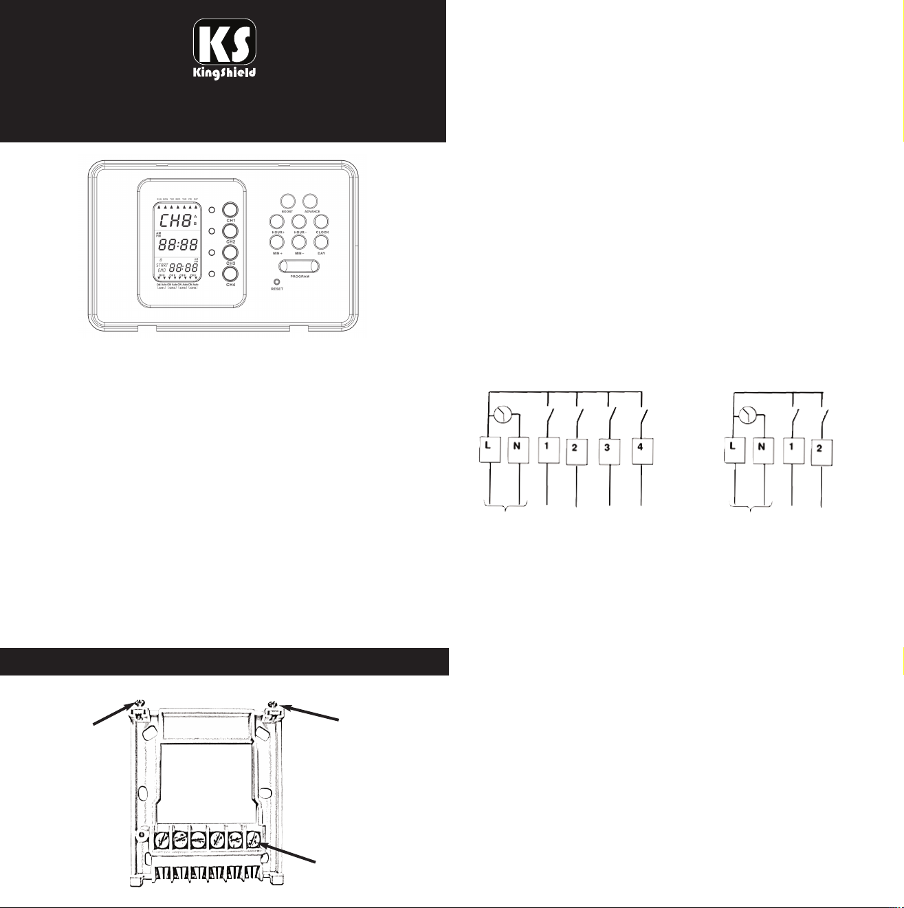
Installation/Operating
Instructions for Central Heating Programmers
- T612A-C & T634A-C
The mounting plate should be carefully removed from the timer by loosening the
two securing screws on the top of the timer and swinging out the mounting plate
away from the body of the timer. The mounting plate should be fitted with the
wiring terminals located at the bottom and in a position which allows the required
clearances around the mounting plate to allow re-fitting of the timer body.
WIRING BOX MOUNTING
The mounting plate may be fitted directly on to a single gang steel flush wiring box
complying with BS4662, using two 3.5mm screws. The T634A-C/T612A-C
programmer is suitable for mounting on a flat surface only; it must not be located
on a surface mounted box or on unearthed metal surfaces.
ELECTRICAL CONNECTIONS
All necessary electrical connections should now be made. Flush wiring can enter
from the rear through the aperture in the mounting plate. The mains supply
terminals are intended to be connected to the supply by means of fixed wiring.
The recommended cable sizes are 1.0mm
The T634A-C/T612A-C programmer is double insulated and does not require an
earth connection. Ensure that no conductors are left protruding outside the
central space encompassed by the mounting plate, and there are no strands of
loose conductors protruding from the terminals.
2
or 2.5mm2.
T612A-C
Central Heating Programmer
7 Day Electronic - 1-2 Channel
T634A-C
Central Heating Programmer
7 Day Electronic - 1-4 Channe
l
(Diagram shown)
The T612A-C (2 Channel)/ T634A-C (4 Channel) programmers are seven day
timers in a slim, elegant enclosure. Each of the two or four channels offers up to
forty programmed operating periods per channel, with a boost and advance
available on each.
Per Channel -
4 ON & 4 OFF settings for everyday of the week.
4 ON & 4 OFF settings for each day block:
Mon - Fri
Mon- Sun
Sat & Sun
This unit should be installed by a competent person in accordance with
the current IEE Wiring Regulations. If in doubt consult a qualified electrician.
Warning: ISOLATE MAINS SUPPLY BEFORE COMMENCING INSTALLATION
INSTALLATION INSTRUCTIONS
FITTING THE MOUNTING PLATE
Securing screws
Securing screws
INTERNAL WIRING DIAGRAM FOR T634A-C and T612A-C
Mains Supply
An example circuit diagram is shown above. This diagram is schematic and
should be used as a guide only. Please ensure that all installations comply with the
current IEE regulations.
FITTING THE PROGRAMMER
Make sure the two securing screws on the top of the mounting plate are loose.
Locate the two lugs on the lower edge of the mounting plate into the two
corresponding apertures on the timer. Swing the top of the timer into position,
ensuring that the connection pins on the rear of the unit locate into the terminal
slots on the mounting plate. Tighten the two securing screws.
T634A-C
Mains Supply
T612A-C
L N CH1 CH2 CH3 CH4
Wiring terminals
Page 2
OPERATING INSTRUCTIONS
This is a four/or two channel programmable timer. It is used for controlling home
appliances such as heaters, lighting systems etc. This timer has 1-2 or 1-4
individual channels. Each channel works in automatic or manual operating mode.
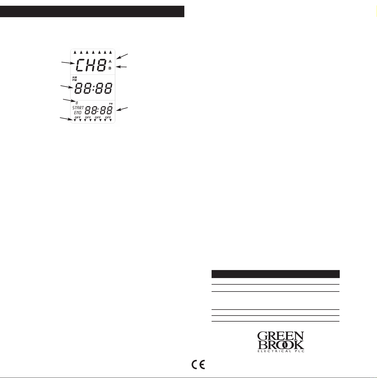
LCD Display Layout
Advance
Channel display
Current time
No of ON/Off
per channel
Channel
state display
Boost
Set time
Reviewing Programs - (applies to each Channel)
Hold down ‘Clock’ and then press a Channel button - the START and END times will
be displayed for 2 to 3 seconds one by one automatically. After completion, the
display will return back to normal LCD display.
Advance Function - (applies to each Channel)
*Used when Channel is in ‘auto mode’.
Hold down ‘Advance’ and then press a Channel button. This will turn on the
Channel. Icon ‘A’ will appear on the LCD screen.
The Channel will turn off at the next programmed ‘OFF’. Icon ‘A’ will disappear from
the LCD screen.
To deactivate hold down ‘Advance’ then press Channel button.
Boost Function - (applies to each Channel)
*Used when Channel is in ‘auto mode’.
Hold down ‘Boost’ and then press a Channel button. This will turn on the
Channel for 1 hour. Icon ‘B’ will appear on the LCD screen.
The Channel will turn off after 1 hour. Icon ‘B’ will disappear from the LCD screen.
To deactivate hold down ‘Boost’ then press Channel button.
IMPORTANT:
Timer to be charged for 1 hour before use.
Timer settings to be conducted while LCD display backlight is ON. The LCD
backlight will be activated when any button is pressed. If no other button is pressed
the backlight will turn OFF after 10 seconds.
Time Function
12hr and 24hr display format selection by pressing CLOCK and HOUR+. The
default is 24hr format, day, hour & minute are shown on the LCD.
Clock setting
Press ‘CLOCK’.
Press ‘Day’ to select correct day.
Press ‘Hour+’ or ‘Hour-’ to select correct hour of the day.
Press ‘Min+’ or ‘Min-’ to select correct minutes.
Note: If buttons are held down for more than 2 seconds they will change continously.
Programming - (Applies to each channel)
Hold down ‘PROGRAM’ and then press the desired channel button.
SET THE START TIME:
1. Press ‘Day’ to select the correct day or day block required.
2. Press ‘Hour+’ or ‘Hour-’ to select correct hour of the day.
3. Press ‘Min+’ or ‘Min-’ to select correct minutes (5 min steps)
4. Press ‘Program’.
SET THE OFF TIME:
1. Press ‘Day’ to select correct day or block required (must be the same as selected
from start time above).
2. Press ‘Hour+’ or ‘Hour-’ to select correct hour of the day.
3. Press ‘Min+’ or ‘Min-’ to select correct minutes.
4. Press ‘Clock’ to finish.
Channel Status Setting
Each Channels status can be set to one of the following settings by pressing the
appropiate Channel button -
Summer Time Setting
To change the time so that is will be one hour ahead.
1. Hold down ‘DAY’ and press ‘Min+’.
2. To cancel hold down ‘DAY’ and press ‘Min+’.
Normal LCD Display
Suppose all the channels are activated and all the channel LED’s are on, CH1 is the
default display even if the timer is in manual or auto mode.
Reset Function
Press RESET to erase all time settings. All the segments on LCD will turn on then
the LCD screen will go back to the normal LCD display. All the channels will work in
AUTO mode. The AUTO icon of each channel will turn on. Monday is selected.
Automatic Return Function
The LCD screen display will return to normal 60 secs after the last button was
pressed.
Backlight Function
The backlight is set to stay on for 10 seconds after a button is pressed.
Memory Kept by Backup Battery
When the power to the timer is lost (i.e. there is a power cut), the built-in battery
back up will ensure the timer stays on. The battery back up can last up to 7 days.
TECHNICAL INFORMATION
Display: LCD
Working Voltage: 230V-50Hz
Max Load of Single Channel:
Resistive - 3A, 690W
Inductive - 1.25A, 230W at 0.8 power factor
Independently Tested to: IEC 60730-2-7. IEC 60730-1
Working Condition: Indoor use only
Please keep these instructions for future reference.
Issue no: 703724
• ON (permanantly ON)
• OFF (permanantly OFF)
• AUTO (will follow programmed times)
WEST ROAD . HARLOW
ESSEX . CM20 2BG . UK
sa les@ gr eenb ro ok. co.u k
WW W.G RE ENB RO OK. CO .U K
 Loading...