

Page 1
nstallation/ Operating Instruction
I
for Fused Spur Switch with Boost Timer
- Model: T206-C
lease read the instructions fully before attempting installation.
P
IMPORTANT
his unit should be installed by a competent person
T
in accordance with the current IET Wiring Regulations.
f in doubt consult a qualified electrician
I
.
• Spur switch must not be mounted on a flammable surface.
• Ensure that the Spur switch does not come into contact with any combustible
materials such as towels or bedding.
• Ensure at least a 300mm air space is allowed around the Spur switch.
• A 12mm pattress is provided if extra spacing is required.
• Twin Earth terminal provided.
Note: Where earthing termination is required this must be connected to a earth
terminal as provided in a metal back box.
OPERATING INSTRUCTIONS
TECHNICAL INFORMATION
Display: LCD
Boost Time: 15 mins - 23 hours
Step Time: 15, 30, 60 Minutes
Working Voltage: 230V~50Hz
Operating Temp: -5°C to +40°C
Operation: Relay Control
Max Load:
Resistive - 13A
Inductive - 6A at 0.4 power factor inductive loading
Isolation: Double Pole Isolation Switch
Conforms to: BS 1363-4:1995+A4:2012,
BS EN 60730-1:2011,
BS EN 60730-2-7:2010.
Working Environment: Indoor use only
Pollution Degree: 2
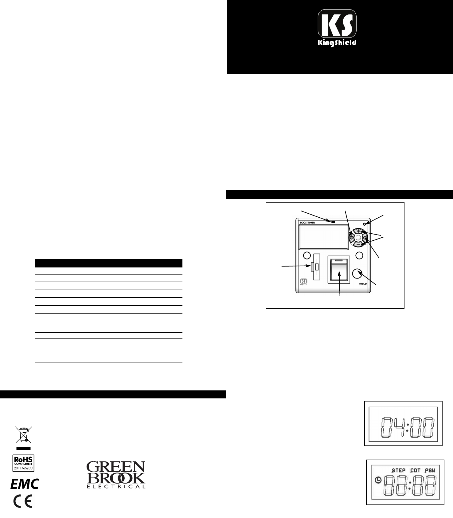
‘ON’ Indicator
Fuse
Holder
Dia.1
Double Pole
Isolation Switch
Set
Button
Reset
Button
‘+’ and ‘
Button
Start/Pause
Button
Front Cable
Entry
-’
Note: When first connected to the power this device will automatically
resort to the default setting
• When power is switched off the timer will automatically reset to
the last saved programmed setting.
• If no new program has been input, it will re-set to default setting
GUARANTEE
Your KingShield Fused Spur Switch with Boost timer
is guaranteed for 12 months from the date of purchase.
This does not affect your statutory rights.
PLEASE KEEP THESE INSTRUCTIONS
SAFE FOR FUTURE REFERENCE
WEST ROAD . HARLOW
ESSEX . CM20 2BG . UK
info @g re en b r ook. co .u k
W W W. G R EE N B R O O K. CO . U K
Default Setting:
- Password: 1234
- Default boost time: 4 hours
- Default step: 1/4 hour
A full display will show when the device reverts
to default screen (04.00) Dia.2.
TO RESET THE DEVICE TO DEFAULT SETTING
To fully reset this unit, press the recessed ‘Reset’
button with an insulated blunt probe, press and
hold simultaneously buttons ‘-’ and ‘set’ buttons
Issue no: 704405
for 10 seconds to reset the device to default setting
in operation - ‘operation’ mode.
(Dia.3 - Full display)
Dia.2
Dia.3
Page 2
HOW TO ‘OPERATE’ BOOST TIMER
ITHIN DEFAULT SETTING
W
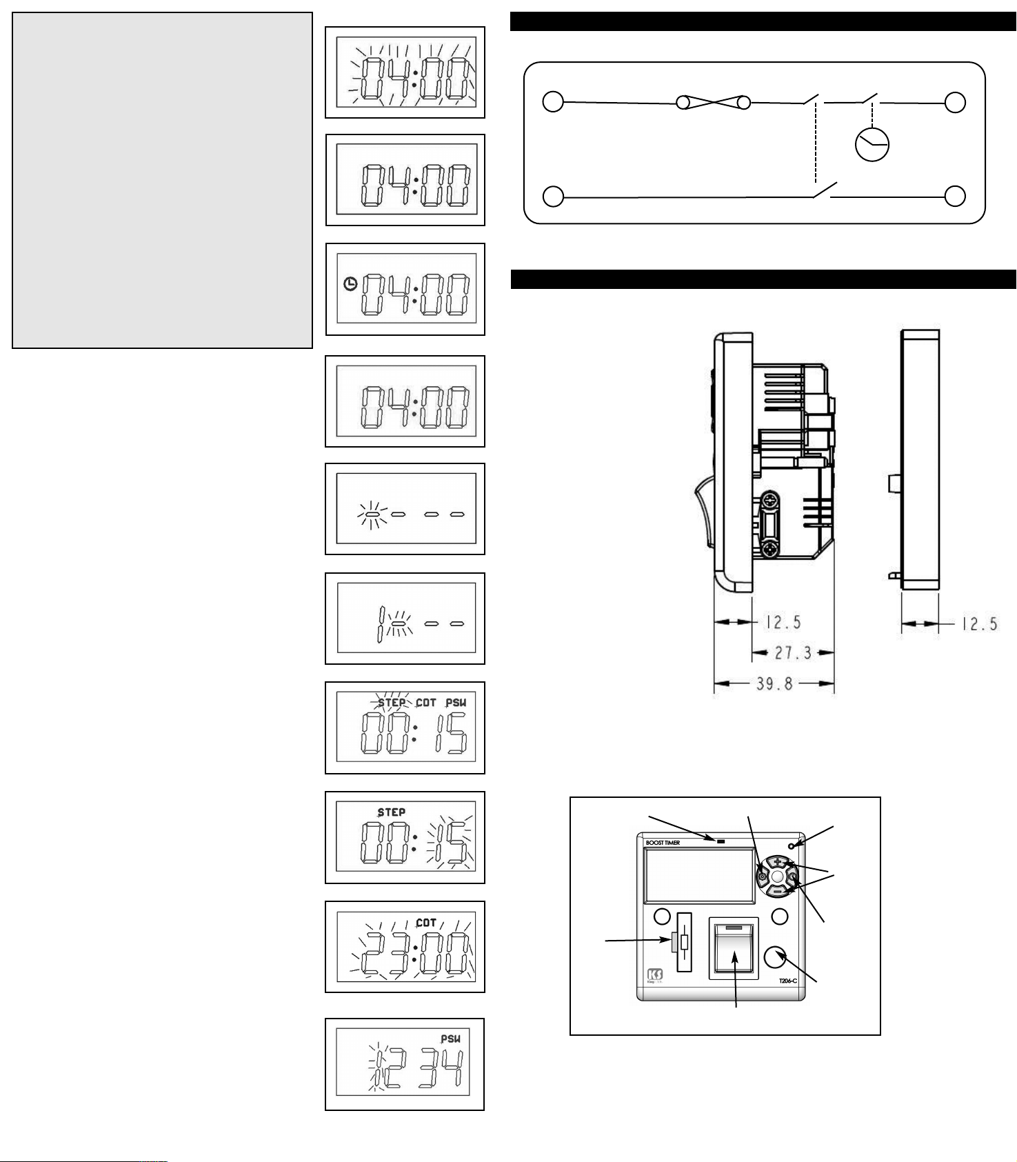
1. Press and hold ‘Set’ button to set the boost
time required. (The display will increase
by 15 minute steps in default mode upto the
limit of 4 hours). Dia.4.
2. Release the ‘Set’ button when the desired time
is shown, limit is now set. Dia.5.
3. Press ‘Start’ button to start or pause the
countdown. Dia.6&7.
Note:
• Pressing the ‘Start’ button to pause the
timer when the timer is running will turn off
power until ‘Start’ is pressed again.
• To reset boost timer to full boost time,
urn isolation switch off and then on.
t
• ‘On’ indicator will flash 2 minutes before timer
reaches ‘00.00’ time.
• The timer will stop automatically, if any setting
is changed.
HOW TO ‘PROGRAM’ FOR
INDIVIDUAL REQUIREMENTS
Display Codes:
STEP = Boost Time Steps CDT = Boost Time PSW = Password
1. Press and hold the ‘+’ and ‘-’ buttons for 2
seconds to enter the default password Dia.8.
To Change the password.Dia:13.
Press ‘+’ or ‘-’ buttons to select the ‘PSW’ and then
press ‘Set’ button to confirm.
Use the ‘+’ or ‘-’ button to change 1st digit as
required, press ‘Set’ to confirm and move to 2nd
digit, repeat for all 4 digits. Pressing ‘Set’ after 4th
digit will revert timer to operating mode.
2. Press the ‘+’ or ‘-’ button to select ‘STEP’, ‘CDT’
or ‘PSW’ setting.
Note: Password must be entered before any ‘STEP’,
‘CDT’ or ‘PSW’ changes can be made.
PRESS SET THEN:
A: Press the ‘+’ or ‘-’ button to set the ‘STEP’
required i.e 15mins, 30 mins or 1 hour. Press the
‘Set’ button to confirm and move to ‘CDT’.Dia:11.
B: Adjust (limit) the amount of hours the
boost timer can be used for - (i.e. 1/4 hour upto 23
hours)Dia:8. ‘CDT’ showing on screen.
Press ‘+’ or ‘-’ button to select maximum amount of
boost hours up to 23, and then press ‘Set’
button to confirm.
Note:
• Settings will return to operating mode, if no
buttons are pressed within 60 seconds.
• If ‘+’ or ‘-’ button is held for more than 2
seconds, the selected digit will add or decrease
quickly (about 3 steps per second)
• Settings will return to operating mode
immediately, if ‘Set’ button is held for more
than 2 seconds.
• When power is switched off the timer will
automatically reset to the last saved
programmed setting.
• The setting will NOT be saved if mains power
goes off whilst programming.
• If no new program has been input, timer will
re-set to default setting.
Dia.4
Dia.5
Dia.6
Dia.7
Dia.8
Dia.9
Dia.10
Dia.11
Dia.12
Dia.13
WIRING DIAGRAM
T206
ime Switch
T
L
In
13A Fuse
N
n
I
Isolation Switch
TECHNICAL DIAGRAM
Note:
This product is
designed to fit in a
25mm, 35mm or
40mm metal or plastic
back boxes.There is an
additional pattress for
mounting on 25mm
boxes.
Allowable Maximum
Load for Lighting
Circuits:
1,000W incandescent,
1000W Halogen, 500W
Fluorescent, 100W
Compact Fluorescent.
1000W LED’s.
‘ON’ Indicator
Fuse
Holder
Dia.1
Note - A separate label has been included in this pack to be located at
the installation site to instruct basic operation. We suggest that if this
unit is to be password protected that the Purchaser/Site Manager
retain the full instructions.
Double Pole
Isolation Switch
Set
Button
Reset
Button
‘+’ and ‘
Button
Start/Pause
Button
Front Cable
Entry
-’
Appliance
L
ut
O
N
ut
O
 Loading...