

GreenBrook PXCSSS-C, PXC105DT-C, PXC2GSW-C, PXC4GSW-C, PXC70TSKT-C Installation Instructions
Page 1
PXC Range of IP66 Rated
Weatherproof 13A Wiring Accessories
All KingShield, PowerX products are suitable for use
outdoors in severe conditions of rain and water spray
as well as dust contamination to IP66 as defined by
BS EN 60529. All PowerX products are for use with a
30V 50Hz supply.
2
INSTALLATION GUIDE - IMPORTANT
This product should only be installed by a competent
and authorised person (e.g. a qualified electrician) in
ccordance with the instructions supplied and in
a
accordance with the appropriate clauses of the current
edition of the IEE Wiring Regulations.
Important -
• Always disconnect the mains supply via the
switch in the main fuse board or consumer unit
before commencing any electrical work.
• Ensure that all terminal screws are fully tightened
and that earth wires are sleeved and that no bare
wires are showing.
• Cable glands must be used which maintain the IP
rating. The warranty is invalid if IP rating is not
maintained.
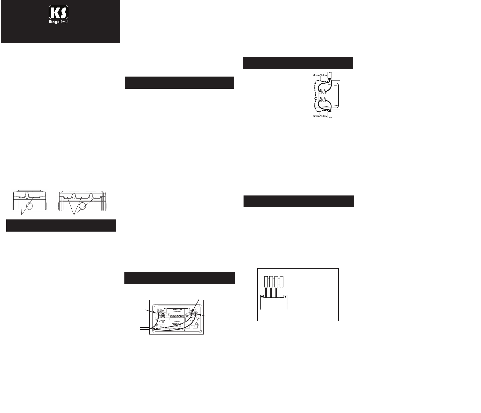
Opening the lid
To open the lid use your thumbs to un-clip the end
snap-shut clips. The lid should then pop open.
SNAPS (lift to open)
INSTALLING THE BOX/ENCLOSURE
1. Ensure that mounting surface is flat and free from
loose particles and dirt.
2. Remove the fitted product by lifting the lid and
unscrewing the two screws. Then remove the
upper portion from the back box by removing the
4 screws on installation. Please note that it is
important to use a screwdriver of a size that
allows you to properly tighten these screws on
installation.
3. Take the back box and drill a small hole through
the drainage point that will be at the lowest point
when mounted. This is necessary to ensure that
any residual moisture or condensation has an
escape route at the back of the box.
4. Use a suitable drill/wall plug for the surface on
which you are mounting your weatherproof
enclosure and use No.8 countersunk screws (not
supplied) to secure the back box through the 4
corner holes.
5. Remove a suitable cable entry cover by pushing
through from the inside of the back box. If
circumstances permit the best entry point for the
supply cable is the bottom one.
6. If cable entry is via 20mm conduit use the conduit
gland to secure the conduit to the back box. If
entry of cable is to be direct use a suitable IP
rated cable gland.
7. Use only 3 core mains cable of sufficient rating for
your application.
8. Screw down the upper portion to the back box
ensuring the collar seal is in position between the
mating surface.
SNAPS (lift to open)
ee the instructions below on how to connect
S
individual products.
9. Mount the accessory onto the box using the
screws as removed in step 2. Ensure the screws
are securely tightened.
Your weatherproof accessory is designed so that IP66
rating can be maintained when an appliance is
plugged into the socket. This is only achieved when
the cover is pressed down firmly so that the cable runs
hrough the centre, and is fully enclosed by the special
t
seal. Always ensure that the cover is located correctly
in place. If in doubt, consult a qualified electrician.
INSTALLING THE INSIDE UNIT
Please refer to the following product sections for
specific information on installation, testing &
operating.
XC22MP-C
P
PXC92MP-C
PXC105DT-C
PXC70TSKT-C
PXC1SW-C, PXC2SW-C, PXC3SW-C, PXC4SW-C
PXCSSS-C, PXC2WTS-C, PXC92N-C
FOR ALL POWERBREAKER RCD UNITS THE
FOLLOWING TEST PROCEDURE APPLIES -
PLEASE CARRY OUT THIS SIMPLE TEST PROCEDURE
PRIOR TO EACH USE.
1. Press ON button - windowindicator will turn red.
3. Press TEST button (T).
4. Red indicator will disappear. This meansthatthe RCD
has tripped successfully.*
5. Toreset – press ON button and use as normal spur.
* If indicator failsto work, test fuse, if unit still fails to
work do not use andreturnto place of purchase.
NOTE 1:
If the Red indication disappears once the socket has been
reset and appliance is firmly plugged in the socket, this
may mean that the appliance or the cable lead is faulty,
and should be checked by a qualified electrician.
NOTE 2:
Remove this RCD from circuit before performing any high
voltage insulation tests.
PXC22MP-C INSTALLING & OPERATING
1. Connect the RCD Socket using the easy to follow
wiring diagram below.
Red (L)
or
Brown
2. If earth conductors are bare they must be sleeved with
appropriate green/yellow sleeving.
N.B. Green/yellow earth wire may be connected to
either earth terminal. Wiring insulation tests should
be completed before setting the PowerBreaker RCD
Socket to avoid misleading instrument readings and
possible internal damage to the unit.
3. Please follow the test procedure above prior to each
use.
IMPORTANT– FOR YOUR PROTECTION.
Electricity can bedangerous and the use of an RCDshould
not be regarded asa substitute for basic electrical safety
Green/Yellow (E)
Black
(N) or
Blue
precautions. Always switch off from supply when working
on equipment. This device will protect against live and
neutral leakage faults to earth, it will not protect against
electric shock due to contact with both conductors, short
ircuits between live and neutral, or a fault in the wiring
c
supplying this device. Should your PowerBreaker Safety RCD
FusedSpur Unit repeatedlytrip with an appliance connected
or fail totrip when tested, in accordance with the
instructions, return to place of purchase.
PXC92MP-C INSTALLING & OPERATING
Supply
Load
Supply
Load
Red or
Brown
Black
or Blue
Black
or Blue
Red or
Brown
. Install RCD spur andconnect
1
wires as shown inthe diagram
below.
2. Any bare earth conductors
ust be sleeved with
m
green/yellow sleeving.
IMPORTANT– FOR YOUR PROTECTION.
Electricity can bedangerous and the use of an RCDshould
not be regarded asa substitute for basic electrical safety
precautions. Always switch off from supply when working
on equipment. This device will protect against live and
neutral leakage faults to earth, it will not protect against
electric shock due to contact with both conductors, short
circuits betweenlive and neutral, or a fault inthe wiring
supplying this device. Should your PowerBreaker Safety RCD
FusedSpur Unit repeatedlytrip with an appliance connected
or fail totrip when tested, in accordance with the
instructions, return to place of purchase.
PXC105DT-C INSTALLING & OPERATING
1. Remove the 2 screws holding the timeswitch
cover to the backplate.
2. Remove the cover leaving the timeswitch hanging
loose by its connection wires to the backplate.
DO NOT INTERFERE WITH THESE FIXED
CONNECTIONS.
3. Connect all earth wires to earthing point in wall box.
4. Offer up the backplate to the wall box and connect
the wiring as shown in diagram. IMPORTANT Ensure all terminal screws are fully tightened.
1. Neutral from mains and
Neutral to appliance.
234
1
5. When the wiring is complete screw the backplate
to the fitted wall box using 3.5mm screws.
6. Push the timeswitch back in to its seating on the
backplate, taking care that all the wires are tucked
in. Fit the cover and tighten the two screws.
Current time and day setting
1. Press the R button to reset the timer to its default
settings, activate using a pencil or similar pointed
instrument (pressing R will delete all stored
programmes).
2. Press Y to enter function setup. (Note: If another
button is not pressed within 10 seconds the
display will revert to the normal screen).
3. Use the + or - button to scroll to the clock icon
2. Live in from mains.
3. Live output to appliance.
4. Not used.
DO NOT INTERFERE WITH
THESE FIXED CONNECTION
T105-C - 230V AC 50HZ 16AMP(2)
flashing) and press Y to enter the current time
(
setting mode (hours flashing).
4. If you keep the + or - buttons pressed for more
than 3 seconds, the display will enter fast scroll
mode.
. Use the + or - button to adjust the hours and
5
press Y to confirm, minutes will flash.
6. Use the + or - button to adjust the minutes and
press Y to confirm, day will flash.
7. Use the + or - button to adjust the day and press
to exit.
N
Programming the switching times
There are 24 ON/OFF programmes available
1. Press the Y button twice to enter the programme
etting mode, (Note: If another button is not
s
pressed within 10 seconds the display will revert
to the normal screen).
2. Default is programme 01 ON, this can be
changed if required by pressing the + or - button
o scroll through the 24 ON/OFF programmes as
t
required, pressing Y will confirm the programme.
3. Press the Y button to confirm programme 01 ON,
hours will flash.
4. Use the + or - button to adjust the hours and
press Y to confirm, minutes will flash.
5. Use the + or - button to adjust the minutes and
press Y to confirm, days will flash.
6. Apart from individual days of the week, the
following day combinations of multiple day blocks
can be selected by pressing the + or - buttons.
• Monday to Sunday
• Monday to Friday
• Saturday & Sunday
• Monday to Saturday
• Monday + Wednesday + Friday
• Tuesday + Thursday + Saturday
• Monday + Tuesday + Wednesday
• Thursday + Friday + Saturday
7. Select day or day block as required and press the
Y button to confirm.
8. Press the + button, this will select the programme
01 OFF, press Y to confirm.
9. Follow 4 to 7 above to set the 01 OFF programme.
(day or day block must be the same as
programme ON).
10. If no more programmes are required, press the N
button to exit.
11. If more programmes are required, follow from
step 3. above.
12. To cancel a programme once set, press and hold
the N button for more than 3 seconds when the
desired programme number is flashing, i.e. to
cancel programme 01 ON, press the Y button
twice and hold the N button down for more than
3 seconds to delete. Pressing the + button again
will select the 01 OFF.
13. Repeat 13 to delete 01 OFF. This procedure can
be repeated to delete any of the 24 programmes.
Timer Countdown function
1. Timer has a 100 hour countdown feature i.e. The
timer can be set to any period from 1 minute to
100 hours and will countdown in the ON state
and turn OFF at the end of the countdown period.
2. Press the Y button then use the + or - button to
select the "down" icon on the right hand side of
the display, press Y again to enter the countdown
mode.
3. Use the + or - button to adjust the hours and
press Y to confirm, minutes will flash.
4. Use the + or - button to adjust the minutes and
press Y to confirm and complete the countdown
Page 2
time setting.
5. Press the N button to start the countdown.
. Output switched to ON during the countdown
6
period.
7. Press the N button to pause the countdown
(output switched to OFF).
8. To resume countdown, press N button again.
. Press and hold the N button for more than 3
9
seconds to exit the countdown function.
Manual Override
1. When in normal clock mode, pressing N button
ill scroll through the following switching options.
w
• ALWAYS ON - timer is permanently ON.
• PROG - timer is in programme ON mode, will
switch off at the next programme OFF time.
ALWAYS OFF - timer is permanently OFF.
•
• PROG - timer is in programme OFF mode, will
switch on at the next programme ON time.
Summer time setting
1. Press the Y button, then use the + or - buttons to
scroll through to "summer" (flashing).
2. Press the Y button again to access the summer
time setting.
3. Press the + or - button to change between
summer on or off.
4. Press Y to confirm summer setting, time will
advance by 1 hour.
5. A "SUMMER" icon will appear in the display.
6. Use the same procedure to remove the
"SUMMER" icon when reverting to GMT in the
winter.
Random setting
The random setting allows the timer to switch ON and
OFF with a random delay of between 2 and 32
minutes. This function will only operate if one or more
switching programmes have been programmed into
the timer.
1. Press the Y button, then use the + or - buttons to
scroll through to "RANDOM" (flashing).
2. Press the Y button again to access the random
setting.
3. Pressing the + or - buttons will toggle the random
icon on and off.
4. Press the Y button to confirm random function.
5. "RANDOM" function icon will appear in display.
6. Timer will now operate in the random mode.
7. To cancel random feature use the procedure
above to remove the "RANDOM" icon from the
display.
Reset
Pressing the reset button R with a pencil or similar will
reset all programmed times and set time of day to
zero.
Reading your programmed times
1. Press Y button twice to enter programme mode.
2. Press the + or - buttons to scroll through the 24
ON/OFF programmes to check settings.
3. Press N button to exit and revert to clock mode.
place with the terminal screw. The screw must
lamp the copper wire not, the insulation fitted to
c
the wire.
3. Any bare earth conductors must be sleeved with
green/yellow sleeving.
Setting the clock
1. Turn the dial in the direction of the arrow
(clockwise) until the correct time and day is
exactly opposite the time set marker on the
clockface (24hr clock).
2. For the “ON” period push the switching green
segments out towards the outside edge of the
face. The timer will operate for the duration set
(each segment is approximately 15 minutes
uration) i.e. if it is required to switch on between
d
16:00 and 18:00, all the segments between these
times should be moved to the outer edge.
By moving the switch located centre right of clock
face the following operations can be achieved.
ON = Timer permanently ON.
AUTO = Timer will work to set program.
OFF = Timer permanently OFF.
PXC1SW-C, PXC2SW-C, PXC3SW-C,
PXC4SW-C INSTALLING & OPERATING
A 1-way switch allows light control from one location
only, 2-way switches control lighting from 2 separate
locations. A 2-way switch may also be used as a 1-way
switch by wiring in accordance with instructions.
1. Only cable of correct current rating and type can
be used. Domestic lighting should use 1.00mm
minimum T&E cable. (Twin and earth cable to
BS6004), although sometimes 3 core and earth is
used for 2-way light switches.
2. Remove only sufficient insulation to ensure direct
contact in the terminals.
3. Position of terminals may differ between fittings,
therefore carefully check the location of the
terminals.
4. Each wire must be connected to the correct
terminal as shown in the diagrams below.
LIGHT SWITCH 1-WAY
Lighting circuit showing 1-way switching
LIGHT SWITCH 2-WAY
Typical lighting circuit showing 2-way switching
2
XCSSS-C, PXC2WTS-C, PXC92N-C
P
INSTALLING & OPERATING
1. Only cable of correct current rating and type can
be used: Domestic 13A circuits normally use
2.5mm2T&E cable.
. Position of terminals may differ between fittings
2
therefore carefully check location of terminals.
3. Remove only sufficient insulation to ensure direct
contact in the terminals.
.a. FOR SOCKET OUTLETS - Each wire must be
4
connected to the correct terminal. The EARTH
wires to the terminal marked E, EARTH ensuring
wire is sleeved with green/yellow sleeving. The
RED or BROWN to terminal marked L. The
LACK or BLUE to terminal marked N.
B
4.b. FOR FUSED SPURS - Each wire must be
connected to the correct terminal. The T&E mains
cable should be connected to the terminals
marked “FEED”, as follows:
RED or BROWN to the terminal marked “L FEED”
BLACK or BLUE to the terminal marked “N
FEED”. The bare earth wires must be covered with
green/yellow PVC sleeving and connected to the
terminal marked .
Connection from this device to the appliance
should utilise flexible cable (to BS6500), of heat
resisting spec. where appropriate. Ensure cable
size suits power rating of appliance. The flexible
cable to the appliance should be connected to this
device using the terminal marked “LOAD”, as
follows: RED or BROWN to the load terminal
marked “LOAD”. BLACK or BLUE to the load
terminal marked “N LOAD”. GREEN/YELLOW to
terminal marked .
5. Ensure that all terminal screws are tightened.
CLEANING
If the unit needs cleaning it should be disconnected from the
mains supply. Wipe the surface with a dry cloth. Do not use a
damp or wet cloth or a solvent based cleaning agent, as this
may damage or impair the safety of the
product.
DISCLAIMER
This equipment is intended for domestic & light commercial
use only. It must be installed in accordance with these fitting
instructions. It should be fixed in the approved &
conventional way to a solid or suitably safe surface.
The equipment should be connected to a mains supply of the
appropriate voltage (indicated on the product). If you are
unsure, consult a qualified electrician before fitting. No liability can be accepted if this product is installed or used in any
other way.
PLEASE NOTE: Electricity is dangerous and can kill. If you
are in any doubt of how to fit your product or there appears
to be damage to the wiring, please consult a qualified
electrician.
PXC70TSKT-C INSTALLING & OPERATING
1. Fit the wiring conductors into the correct
terminals of the socket.
LIVE (L) = RED OR BROWN
NEUTRAL (N) = BLACK OR BLUE
EARTH (E) = GREEN/YELLOW
2. Check that all bare wires are firmly housed in the
correct terminals before clamping, tightening in
+ L LIVE = (Brown or Red)
- N NEUTRAL = (Black or Blue)
E EARTH = (Green/Yellow)
LIVE (L) = RED OR BROWN
NEUTRAL (N) = BLACK OR BLUE
EARTH (E) = GREEN/YELLOW
WEST ROAD . HARLOW
ESSEX . CM20 2BG . UK
sa le s@g re enbro ok .co .u k
W WW .G R E EN B RO O K .C O .U K
Issue No: 702727
 Loading...