

GREE GWHD(18)ND6MO, MUL18HP230V1R32AO, GWHD(24)ND6MO, MUL24HP230V1R32AO, GWHD(30)ND6MO User Guide
...Page 1

Change for life
Owner's Manual
Original Instructions
Split Air Conditioner
Thank you for choosing our product.
Please read this Owner’s Manual carefully before operation and
retain it for future reference.
If you have lost the Owner's Manual, please contact the local agent
or visit www.gree.com or send an email to JOREDO#FQJUHHFRP for
the electronic version.
Page 2
GWHD(18)ND6MO MUL18HP230V1R32A
GWHD(24)ND6MO MUL24HP230V1R32AO
GWHD(30)ND6MO MUL30HP230V1R32AO
GWHD(36)ND6MO MUL36HP230V1R32AO
GWHD(42)ND6MO MUL42HP230V1R32AO
O
Page 3
In line with the company’s policy of continual product improvement, the aesthetic and dimensional
characteristics, technical data and accessories of this appliance may be changed without notice.
CONTENTS
CONFORMITY AND RANGE
THE REFRIGERANT
SAFETY OPERATION OF FLAMMABLE REFRIGERANT
WARNING
THE INSTRUCTIONS BEFORE USE
GENERAL
NAME OF PARTS
INFORMATION
OUTDOOR UNIT WORKING TEMPERATURE RANGE
ELECTRICAL CONNECTIONS
INSTALLING THE OUTDOOR UNIT
BLEEDING
MAINTENANCE
INSTALLATION DIMENSION DIAGRAM
INSTALLER
CHECK AFTER INSTALLATION
SPECIALIST’S MANUAL
GENERAL INFORMATION
1
2
2
5
9
10
10
11
15
15
16
16
17
18
The products in this manual may be different with the real one, according to different models,
some models have displayer and some models without displayer, the position and shape of
the displayer please refer to the real one.
This appliance is not intended for use by persons (including children) with reduced physical,
sensory or mental capabilities, or lack of experience and knowledge, unless they have been
given supervision or instruction concerning use of the appliance by a person responsible for
their safety.
Children should be supervised to ensure that they do not play with the appliance.
If it needs to install, move or maintain the air conditioner, please contact dealer or local service
center to conduct it at first. Air conditioner must be installed, moved or maintained by appointed
unit. Otherwise, it may cause serious damage or personal injury or death.
When refrigerant leaks or requires discharge during installation, maintenance, or disassembly,
it should be handled by certified professionals or otherwise in compliance with local laws and
regulations.
Page 4
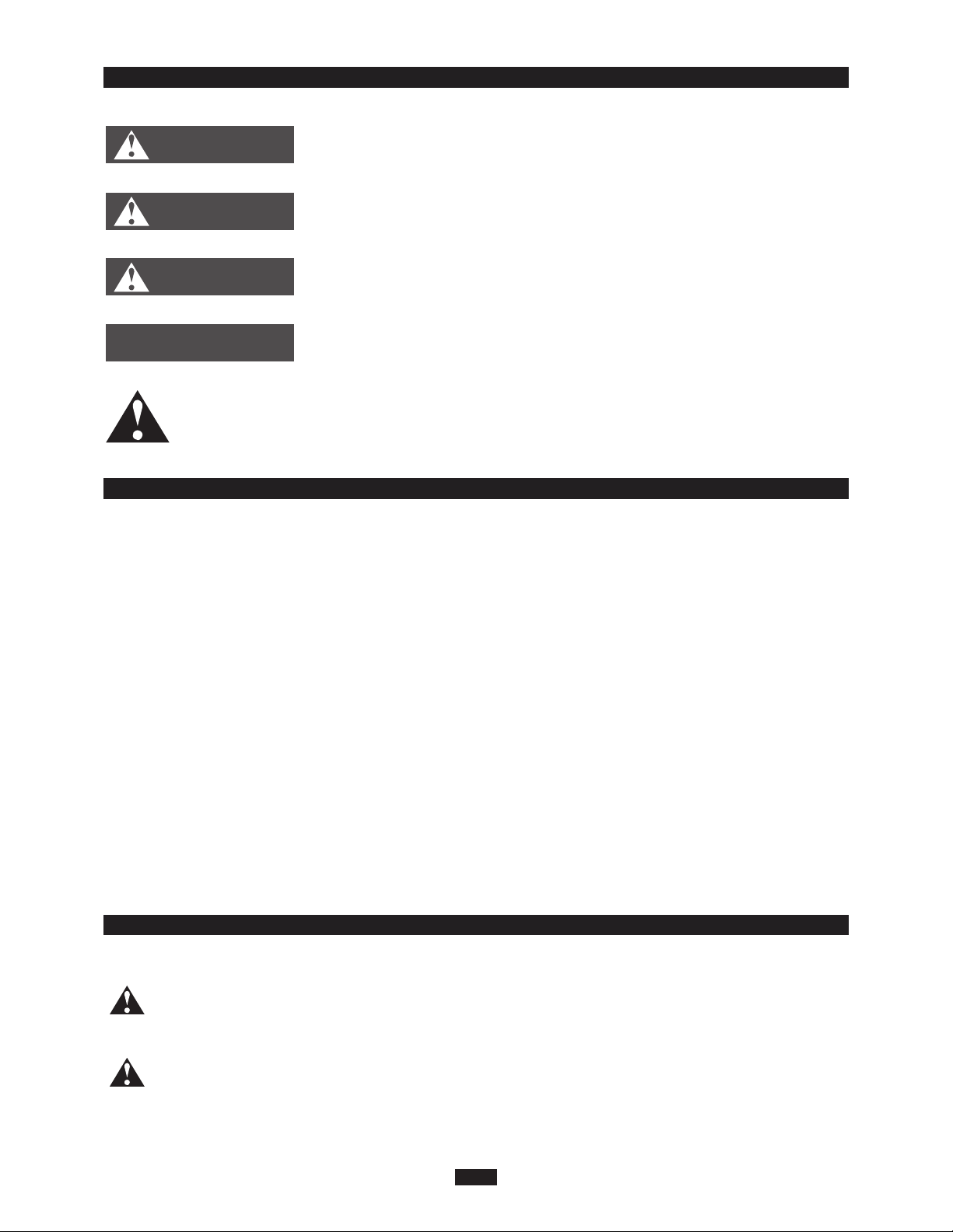
DANGER
WARNING
GENERAL INFORMATIONEXPLANATION OF SYMBOLS
Indicates a hazardous situation that, if not avoided, will
result in death or serious injury.
Indicates a hazardous situation that, if not avoided, could
result in death or serious injury.
CAUTION
result in minor or moderate injury.
Indicates important but not hazard-related information,
Indicates a hazardous situation that, if not avoided, may
NOTICE
used to indicate risk of property damage.
Indicates a hazard that would be assigned a signal word
WARNING or CAUTION.
GENERAL INFORMATIONEXCEPTION CLAUSES
Manufacturer will bear no responsibilities when personal injury or
property loss is caused by the following reasons.
1.Damage the product due to improper use or misuse of the product;
2.Alter, change, maintain or use the product with other equipment without abiding
by the instruction manual of manufacturer;
3.After verification, the defect of product is directly caused by corrosive gas;
4.After verification, the defects are due to improper operation during transportation
of product;
5.Operate, repair, maintain the unit without abiding by instruction manual or related
regulations;
6.After verification, the problem or dispute is caused by the quality specification or
performance of parts and components that produced by other manufacturers;
7.The damage is caused by natural calamities, bad using environment or force
majeure.
CONFORMITY AND RANGE
Please read this owner's manual carefully before operating the unit and keep it
carefully for consultation.
Only use the air conditioner as instructed in this booklet. These instructions are
not intended to cover every possible condition and situation. As with any electrical
household appliance, common sense and caution are therefore always
recommended for installation, operation and maintenance.
1
GENERAL INFORMATION
Page 5
The refrigerant
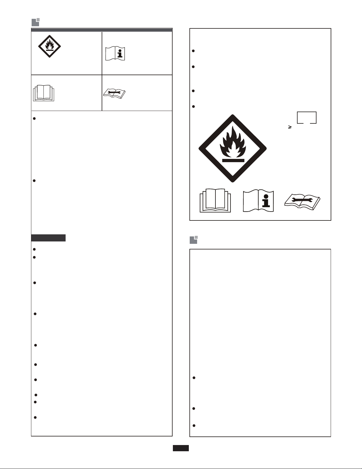
Refrigerant
Safety Group
A2L
Appliance filled with
flammable magas R32.
Before use the
appliance, read
the owner’s manual first.
T
o realize the function of the air conditioner unit,
a special refrigerant circulates in the system.
The used refrigerant is the fluoride R32, which
is specially cleaned.
and inodorous. Furthermore, it can lead to explosion
mability of the refrigerant is very low. It can be
ignited only by fire.
Compared to common refrigerants, R32 is a
nonpolluting refrigerant with no harm to the
ozonosphere . The influence upon the greenhouse effect is also lower . R32 has got very
good thermodynami c features which lead to a
really high energy e fficiency. The units there
fore need a less filling.
under certain conditions. But the flam-
The refrigerant is flammable
Before install the
appliance, read
the installation
manual first.
Before repair the
appliance, read
the service manual first.
process or to clean,other than those recomm-
ended by the manufacturer.
Servicing shall be performed only as recommended by the manufacturer.
Should repair be necessary,contact your nearest
authorized Service Centre. Any repairs carried out
by unqualified personnel may be dangerous.
Compliance with national gas regulations shall
be observed.
Read specialist’s manual.
2
2
PIW
Refrigerant
Safety Group
A2L
WARNING
Appliance filled with flammable gas R32.
$SSOLDQFHVKDOOEHLQVWDOOHGRSHUDWHGDQG
VWRUHGLQDURRPZLWKDIORRUDUHDQRWOHVVWKDQ
2
PIW
The appliance shall be stored in a room without
continuously operating ignition sources.
(for example:open flames,an operating gas appliance or an operating electric heater.)
The appliance shall be stored in a wellventilated area where the room size
corresponds to the room area as specified for
operation.
The appliance shall be stored so as to prevent
mechanical damage from occurring.
Ducts connected to an appliance shall not contain an ignition source.
Keep any required ventilation openings clear of
obstruction.
Do not pierce or burn.
Be aware that refrigerants may not contain an
odour.
Do not use means to accelerate the defrosting
2
Safety operation of flammable refrigerant
Qualification of workers
Qualification of the working personnel for
maintenance, service and repair operations
should according to UL 60335-2 -40、CAN/C-
SA-C22.2 No. 60335-2-40:22 Annex HH..
Every working procedure that affects safety
means shall only be carried out by competent persons according to Annex HH. Special
training additionalto usual refrigerating equipment repair procedures is required when
equipment with FLAMMABLE REFRIGERANTS is affected.
Installation notes
The air conditioner must be installed in a room
that is larger than the minimum room area. The
minimum room area is shown on the nameplate
or following table a.
It is not allowed to drill hole or burn the connection pipe.
Leak test is a must after installation.
2
Page 6
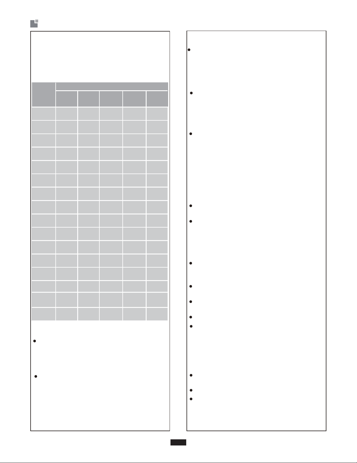
Safety operation of flammable refrigerant
table a - Minimum room area ( m 2 )
%DVHGRQ8/UHTXLUHPHQWV
7KHIROORZLQJLQVWDOODWLRQKHLJKWDQGDUHDIRU
FXVWRPHUUHIHUHQFH
Charge
amount
(kg)
1.85
1.9
1.95
2
2.05
2.1
2.15
2.2
2.3
+HLJKWRIYHQWLODWLRQRSHQLQJP
0.6
/
29.4
31.0
32.7
34.4
36.1
37.9
39.7
41.6
45.5
1.8
//
6.8
6.9
7.1
7.3
7.5
7.7
7.9
8.0
8.4
2.2
5.5
5.7
5.8
6.0
6.1
6.3
6.4
6.6
6.9
2.5 3
//
4.9 4.1
5.0 4.2
5.1 4.3
5.3 4.4
5.4 4.5
5.5 4.6
5.7 4.7
5.8 4.8
6.1 5.1
Check whether there is fire source or potential
fire source in the maintenance area.
- The naked flame is prohibited in the mainte-
nance area; and the “no smoking” warning
board should be hanged.
Check whether the appliance mark is in good
condition.
- Replace the vague or damaged warning mark.
Welding
If you should cut or weld the refrigerant system
pipes in the process of maintaining, please follow the steps as below:
Shut down the unit and cut power supply
a.
Eliminate the refrigerant
b.
Vacuuming
c.
Clean it with N
d.
e.
Cutting or welding
f.
Carry back to the service spot for welding
The refrigerant should be recycled into the specialized storage tank.
Make sure that there isn’t any naked flame ne-
ar the outlet of the vacuum pump and it’s well-
ventilated.
2
gas
2.4
2.5
2.6
2.7
2.8
2.9
49.5
53.7
58.1
62.6
67.4
72.3
8.8
9.1
9.5
9.8
10.2
10.6
7.2
7.5
7.8
8.1
8.4
8.7
6.3 5.3
6.6 5.5
6.8 5.7
7.1 5.9
7.4 6.2
7.6 6.4
Maintenance notes
Check whether the maintenance area or the room area meet
- It’s only allowed to be operated in the rooms
that meet the requirement of the nameplate.
Check whether the maintenance area is wellventilated.
- The continuous ventilation status should be
kept during the operation process.
the requirement of the nameplate.
Filling the refrigerant
Use the refrigerant filling appliances specialized for R32. Make sure that different kinds
of refrigerant won’t contaminate with each other.
The refrigerant tank should be kept upright at
the time of filling refrigerant.
Stick the label on the system after filling is finished (or haven’t finished).
Don’t overfilling.
After filling is finished, please do the leakage
detection before test running; another time of
leak detection should be done when it’s removed.
Safety instructions
for transportation and storage
Please use the flammable gas detector to check before unload and open the container.
No fire source and smoking.
According to the local rules and laws.
3
Page 7
Safety operation of flammable refrigerant
Safety of Construction
For appliances using FLAMMABLE REFRIGERANTS, all joints made in the installation
between parts of the REFRIGERATING
SYSTEM, with at least one part charged,
shall be made in accordance with the
following:
–
A brazed, welded, or mechanical connection
shall be made before opening the valves to
permit refrigerant to flow between the
REFRIGERATING SYSTEM parts. A vacuum
valve shall be provided to evacuate the interconnecting pipe or any uncharged REFRIGERATING SYSTEM part.
–
Mechanical connectors used indoors shall
comply with ISO 14903. When mechanical
onnectors are reused indoors, sealing parts
c
shall be renewed. When fl
ed indoors, the flare part shall be refabri-
reus
cated.
–
Refrigerant tubing shall be protected or
HQFORVHGWRDYRLGGDPDJH
ared joints are
Field-made refrigerant joints indoors shall
be tightness tested. The test method shall
have a sensitivity of 5 grams per year of
refrigerant or better under a pressure of at
least 0,25 times the maximum allowable
pressure. No leak shall be detected.
–
F
lexible refrigerant connectors (such as connecting lines between the indoor and outd
unit) that may be displaced during NORMAL
OPER
mec
ATION shall be protec
hanical damage.
ted against
Pressure test and leak detect
After completion of field piping for split
systems, the field pipework shall be pressure
tested with an inert gas and then vacuum
tested prior to refrigerant charging, according
to the following requirements.
The minimum test pressure for the low
side of the system shall be the low side
design pres-sure and the minimum test
pressure for the high side of the system
shall be the high side design pressure,
unless the high side of the system,
cannot be isolated from the low side of the
system in which case the entire system
shall be pressure tested to the low side
design pressure.
oor
4
Page 8
WARNING
GENERAL INFORMATION
Operation and Maintenance
This appliance can be used by children aged from 8 years and above and
persons with reduced physical, sensory or mental capabilities or lack of
experience and knowledge if they have been given supervision or instruction
concerning use of the appliance in a safe way and understand the hazards
involved.
Children shall not play with the appliance.
Cleaning and user maintenance shall not be made by children without
supervision.
Do not connect air conditioner to multi-purpose socket. Otherwise, it may
cause fire hazard.
Do disconnect power supply when cleaning air conditioner. Otherwise, it
may cause electric shock.
If the supply cord is damaged, it must be replaced by the manufacturer, its
service agent or similarly qualified persons in order to avoid a hazard.
Do not wash the air conditioner with water to avoid electric shock.
Do not spray water on indoor unit. It may cause electric shock or malfunction.
After removing the filter, do not touch fins to avoid injury.
Do not use fire or hair dryer to dry the filter to avoid deformation or fire hazard.
Maintenance must be performed by qualified professionals. Otherwise, it may
cause personal injury or damage.
Do not repair air conditioner by yourself. It may cause electric shock or damage.
Please contact dealer when you need to repair air conditioner.
Do not extend fingers or objects into air inlet or air outlet. It may cause personal
injury or damage.
Do not block air outlet or air inlet. It may cause malfunction.
Do not spill water on the remote controller, otherwise the remote controller may
be broken.
When below phenomenon occurs, please turn off air conditioner and disconnect
power immediately and then contact the dealer or qualified professionals for
service.
Power cord is overheating or damaged.
There’s abnormal sound during operation.
Circuit break trips off frequently.
Air conditioner gives off burning smell.
Indoor unit is leaking.
5
Page 9
WARNING
GENERAL INFORMATION
If the air conditioner operates under abnormal conditions, it may cause
malfunction,electric shock or fire hazard.
When turning on or turning off the unit by emergency operation switch, please
press this switch with an insulating object other than metal.
Do not step on top panel of outdoor unit, or put heavy objects. It may cause
damage or personal injury.
For appliances made up of more than one factory made assembly specified
by the manufacturer to be used together, instructions shall be provided for
completing the assembly to ensure compliance with the requirements.
Attachment
Installation must be performed by qualified professionals. Otherwise, it may
cause personal injury or damage.
Must follow the electric safety regulations when installing the unit.
According to the local safety regulations, use qualified power supply circuit
and circuit break.
Do install the circuit break. If not, it may cause malfunction.
Means for disconnection must be incorporated in the fixed wiring in accordance
with the wiring rules.
Including an circuit break with suitable capacity, please note the following table.
Air switch should be included magnet buckle and heating buckle function, it can
protect the circuit-short and overload.
Air Conditioner should be properly grounded. Incorrect grounding may cause
electric shock.
Don't use unqualified power cord.
Make sure the power supply matches with the requirement of air conditioner.
Unstable power supply or incorrect wiring may result in electric shock, fire
hazard or malfunction. Please install proper power supply cables before using
the air conditioner.
Properly connect the live wire, neutral wire and grounding wire of power socket.
Be sure to cut off the power supply before proceeding any work related to
electricity and safety.
Do not put through the power before finishing installation.
If the supply cord is damaged, it must be replaced by the manufacturer, its
service agent or similarly qualified persons in order to avoid a hazard.
The temperature of refrigerant circuit will be high, please keep the
interconnection cable away from the copper tube.
6
Page 10
WARNING
GENERAL INFORMATION
The appliance shall be installed in accordance with national wiring regulations.
Installation must be performed in accordance with the requirement of NEC and
CEC by authorized personnel only.
The air conditioner is the first class electric appliance. It must be properly
grounding with specialized grounding device by a professional. Please make
sure it is always grounded effectively, otherwise it may cause electric shock.
The yellow-green wire in air conditioner is grounding wire, which can't be used
for other purposes.
The grounding resistance should comply with national electric safety regulations.
The appliance must be positioned so that the plug is accessible.
All wires of indoor unit and outdoor unit should be connected by a professional.
If the length of power connection wire is insufficient,please contact the
supplier for a new one. Avoid extending the wire by yourself.
For the air conditioner with plug,the plug should be reachable after finishing
installation.
For the air conditioner without plug, an circuit break must be installed in the line.
If you need to relocate the air conditioner to another place, only the qualified
person can perform the work. Otherwise, it may cause personal injury or damage.
Select a location which is out of reach for children and far away from animals or
plants.If it is unavoidable, please add the fence for safety purpose.
The indoor unit should be installed close to the wall.
Before operation, please confirm whether power specification complies with
that on nameplate.
Before cleaning or maintaining the air conditioner, please turn off air conditioner
and pull out the power plug.
Make sure the power cord hasn’ t been pressed by hard objects.
Do not pull or drag the power cord to pull out the power plug or move the air
conditioner.
Do not insert or pull out the power plug with wet hands. Please use the grounded
power. Make sure the grounding is reliable.
If the SUPPLY CORD is damaged, it must be replaced by the manufacturer,
its service agent or similarly qualified persons in order to avoid a hazard.
If abnormal condition occurs (e. g. burned smell), please disconnect power
at once and then contact local dealer.
When nobody is taking care of the unit, please turn it off and remove the power
plug or disconnect power.
7
Page 11
WARNING
GENERAL INFORMATION
Do not splash or pour water on air co nditioner. Otherwise, it may cause short
circuit or damage to air conditioner.
Prohibit operating heating equipment around the air conditioner.
Prohibit operating the unit in the bathroom or laundry room.
Far away from fire source, inflammable and explosive objects.
Keep children from playing or climbing on the air conditioner.
Do not put or hang dripping objects above the air conditioner.
Do not repair or disassemble the air conditioner by yourself.
Do not block air outlet or air inlet.
Prohibit inserting any objects into the air conditioner.
Do not through sundries into the air duct. If there are sundries get into the air
duct, please contact the professionals to deal with it.
Do not use an extension cord.
A fuse or circuit breaker should be added at the product circuit. Please refer
to the MOP value on the nameplate for the detailed specification.
The appliance shall be installed in accordance with national wiring regulations.
If a STATIONARY APPLIANCE is not fitted with a SUPPLY CORD and a plug,
an all-pole disconnection switch having a contact separation of at least 3mm
in all poles should be connected in fixed wiring.
8
Page 12
THE INSTRUCTIONS BEFORE USE GENERAL INFORMATION
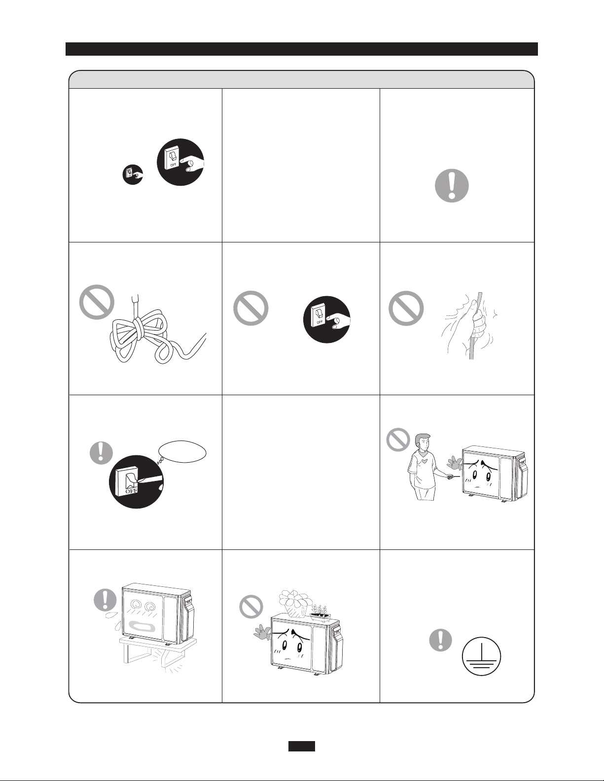
WARNING
When having a burning smell or
ƾƾ
smoke,please turn off the power
supply and contact with the service center.
If the abnormity still exists,the unit
may be damaged,and may cause
electric shock or fire.
Power must adopts the special
ƾ
circuit to prevent fire.
Otherwise, it can cause electric
shock or fire.
The power supply must adopt the
special circuit that with air switch
protection and assure it has enough capacity.The unit will be turned
on or off according to your requirement automatically,please do not
turn on or turn off the unit frequently,otherwise disadvantage effect
may be caused to the unit.
Disconnect the power supply if
ƾƾ
long putting the air conditioner
out of use.
Otherwise,the accumulated dusts
may cause overheating or fire.
Never cut off or damage power
ƾ
cables and control wires. If the
power cable and signal control
wire were damaged, change
them by professional.
Never damage the electric wire
or use the electric wire which is
not appointed.
Otherwise,it will cause overheating
or fire.
When cleaning,it is necessary
ƾƾ
to stop driving and turn off the
power supply.
Cut off power supply
Otherwise,it may cause electric
shock or damage.
Please note whether the insta-
ƾƾƾƾ
lled stand is firm enough or not.
If it is damaged, it may lead to the
fall of the unit and cause the injury.
Rated voltage of this air conditioner 208/230V, 60Hz, The compressor will vibrate sharply if the
voltage is too low, resappointed.
amage to refrigerating system.
Electrical component are easy to
damage if the voltage is too high.
The wrong repair will lead to an
electric shock or fire,so you should
contact the service center to repair.
Don't step on the top of the
outdoor unit or place something
on it.
As falling off the outdoor unit can be
dangerous.
Don't attempt to repair the air
conditioner by yourself.
Earthing: The unit must be reliably earthed.The earthing cable
shall be connected to the special earthing device in the construction.
Page 13
NAME OF PARTS GENERAL INFORMATION
WARNING
Be sure to cut off the power supply before cleaning the air conditioner; otherwise electric shock might happen.
any case.
Volatile liquids such as thinner or gasoline will cause damage to the appearance of air conditioner. (Only use
soft dry cloth moist cloth clean the air conditioner cabinet).
This product must not be disposed together with the domestic waste.
This product has to be disposed at an authorized place for recycling of electrical and electronic appliances.
The temperature of refrigerant circuit will be high,please keep the interconnection cable away from the copper
tube.
1
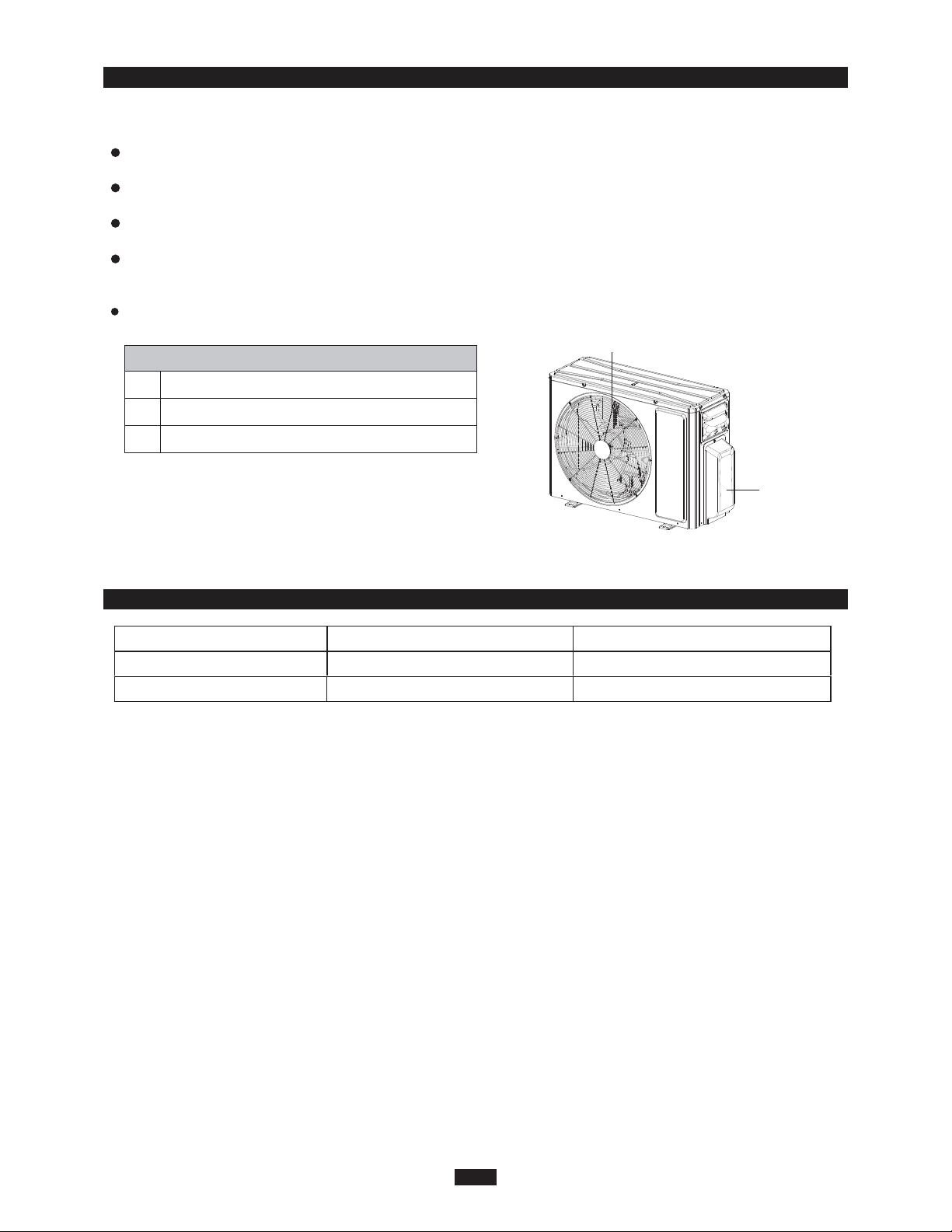
OUTDOOR UNIT
No. Description
1 Air outlet grille
2 Valve
ni renoitidnoc ria ruoy hsaw ot ton erus ekaM .kcohs cirtcele fo ksir eht esuac yam renoitidnoc ria fo gnitteW
Note: The above figures are only intended to a simple
diagram of the appliance and may not correspond to the
appearance of the units that have been purchased.
OUTDOOR UNIT WORKING TEMPERATURE RANGE GENERAL INFORMATION
2
Indoor side DB/WB(°C/°F) Outdoor side DB/WB(°C/°F)
Maximum cooling 26.7/19.4(80/67)
Maximum heating 26.7/-(80/-)
48/24(118/75)
23.9/18.3(75/65)
Ɣ The operating temperature range (outdoor temperature):
Cooling only unit: -30°C ~ 48°C(-22°F ~ 118°F);
Heat pump unit: for cooling mode is -30°C ~ 48°C(-22°F ~ 118°F);
for heating mode is -30°C ~ 24°C(-22°F ~ 75.2°F).
10
Page 14
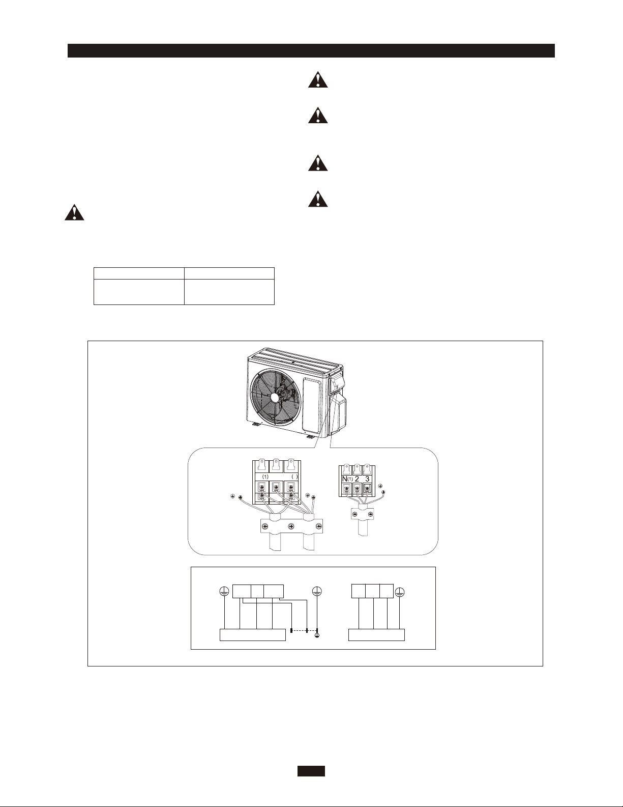
ELECTRICAL CONNECTIONS
Remove the handle at the right side plate of the
1.
outdoor unit (one screw).
2.
Remove the cable clamp, connect the power
connection cable with the terminal at the row of
connection and fix the connection. The fitting line
distributing must be consistent with the indoor
unit. terminal of line bank. Wiring should meet
that of indoor unit.
3. Fix power connection wire by wire clamp.
4.
Ensure wire has been fixed well.
5.
Install the handle.
Including an air switch with suitable capacity,
please note the following table. Air switch
should be included magnet buckle and heating
buckle function, it can protect the circuit-short
and overload. (Caution: please do not use the
fuse only for protect the circuit)
Air-conditioner Air switch capacity
INSTALLER
An all-pole disconnection switch having a contact
separation of at least 3mm in all pole should be
connected in fixed wiring.
Wrong wire connection may cause malfunction of
some electric components.After fixing cable, ensure
that leads between connection to fixed point have
some space.
The connection pipes and the connection wirings
of the unit A, unit B must be corresponding to each
other respective.
The appliance shall be installed in accordance with
national wiring regulations.
Note: The above figures are only intended to be a simple
diagram of the appliance and may not correspond to the
appearance of the units that have been purchased.
GWHD(18)ND6MO
20A
L1(1) L2(3)
L1
2
Power cord
A
To unit A
2
To unit B
3
L2
connecting
connecting
cable
cable
To the power supply
B
N(1)
23
green
white
(yellow
(blue)
-green)
INDOOR UNIT A
L1 L2
POWER
green
(yellow
-green)
white
black
(blue)(blue)
INDOOR UNIT B
black red red
white black
(brown) (brown)(brown)
11
green
(yellow
-green)
Page 15
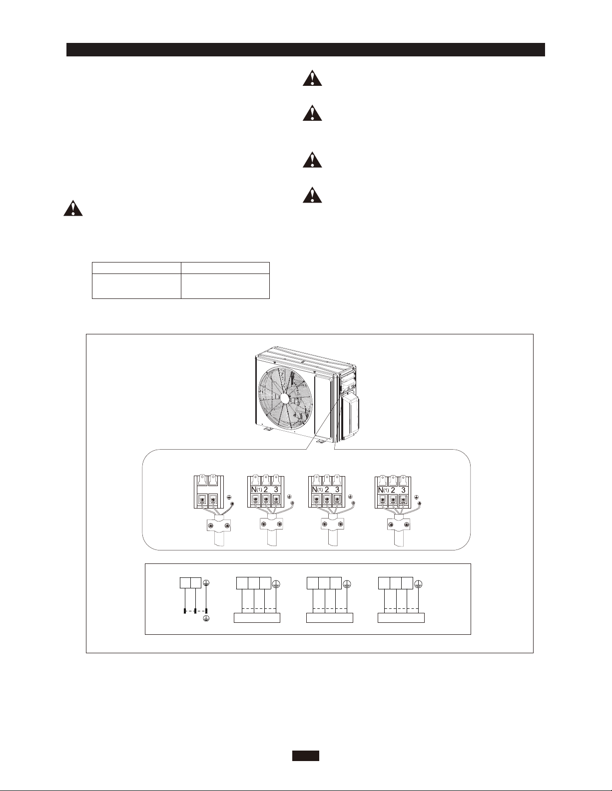
ELECTRICAL CONNECTIONS
Remove the handle at the right side plate of the
1.
outdoor unit (one screw).
2.
Remove the cable clamp, connect the power
connection cable with the terminal at the row of
connection and fix the connection. The fitting line
distributing must be consistent with the indoor
unit. terminal of line bank. Wiring should meet
that of indoor unit.
3. Fix power connection wire by wire clamp.
4.
Ensure wire has been fixed well.
5.
Install the handle.
Including an air switch with suitable capacity,
please note the following table. Air switch
should be included magnet buckle and heating
buckle function, it can protect the circuit-short
and overload. (Caution: please do not use the
fuse only for protect the circuit)
Air-conditioner Air switch capacity
INSTALLER
An all-pole disconnection switch having a contact
separation of at least 3mm in all pole should be
connected in fixed wiring.
Wrong wire connection may cause malfunction of
some electric components.After fixing cable, ensure
that leads between connection to fixed point have
some space.
The connection pipes and the connection wirings
of the unit A, unit B and unit C must be corresponding
to each other respective.
The appliance shall be installed in accordance with
national wiring regulations.
Note: The above figures are only intended to be a simple
diagram of the appliance and may not correspond to the
appearance of the units that have been purchased.
GWHD(24)ND6MO
black
(brown)
/ /
L1 L2
//
white
(blue)
32:(5
25A
Power cord
green
(yellow-green)
1
white red
black
(blue)
,1'22581,7$
To unit BTo unit A
connecting
cable
$
green
(brown)
(yellow-green)
1
white red
black
(blue)
,1'22581,7%
connecting
cable
%
(brown)
green
(yellow-green)
To unit C
connecting
cable
To the power supply
&
1
white red
(brown)
black
(blue)
,1'22581,7&
green
(yellow-green)
12
Page 16
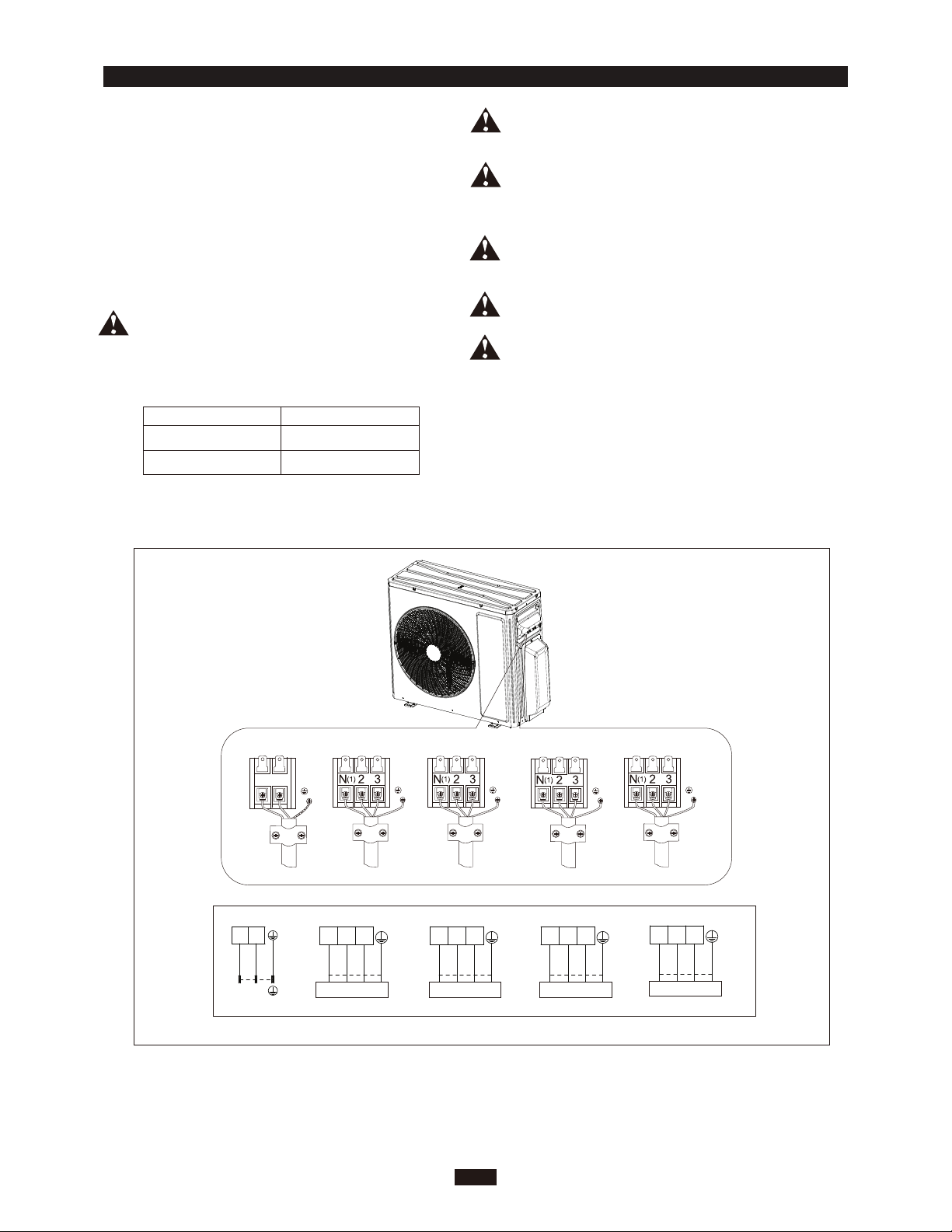
ELECTRICAL CONNECTIONS
1.
Remove the handle at the right side plate of the
outdoor unit (one screw).
2.
Remove the cable clamp, connect the power
connection cable with the terminal at the row of
connection and fix the connection. The fitting line
distributing must be consistent with the indoor
unit. terminal of line bank. Wiring should meet
that of indoor unit.
3. Fix power connection wire by wire clamp.
4.
Ensure wire has been fixed well.
5.
Install the handle.
Including an air switch with suitable capacity,
please note the following table. Air switch
should be included magnet buckle and heating
buckle function, it can protect the circuit-short
and overload. (Caution: please do not use the
fuse only for protect the circuit)
Air-conditioner Air switch capacity
GWHD(30)ND6MO
GWHD(36)ND6MO 45A
35A
INSTALLER
An all-pole disconnection switch having a contact
separation of at least 3mm in all pole should be
connected in fixed wiring.
Wrong wire connection may cause malfunction of
some electric components.After fixing cable, ensure
that leads between connection to fixed point have
some space.
The connection pipes and the connection wirings
of the unit A, unit B, unit C and unit D must be corresponding to each other respective.
The appliance shall be installed in accordance with
national wiring regulations.
WARNING: Communication cables should be laid
out through cabling trough, conduit tube or cable
channel; otherwise, it may cause electric shock
or death.
Note: The above figures are only intended to be a simple
diagram of the appliance and may not correspond to the
appearance of the units that have been purchased.
black
(brown)
/ /
L1 L2
//
white
(blue)
32:(5
Power cord
green
(yellow-green)
1
white red
black
(blue)
,1'22581,7$
To unit BTo unit A
connecting
cable
$
green
(brown)
(yellow-green)
connecting
cable
%
1
white red
black
(blue)
,1'22581,7%
(brown)
green
(yellow-green)
13
To unit C
connecting
cable
1
white red
black
(blue)
,1'22581,7&
To the power supply
&
green
(brown)
(yellow-green)
To unit D
connecting
cable
1
white red
black
(blue)
,1'22581,7'
'
(brown)
green
(yellow-green)
Page 17
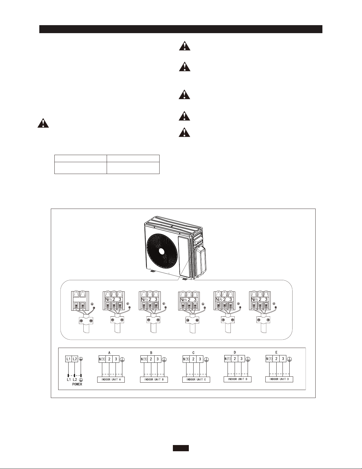
ELECTRICAL CONNECTIONS
1.
Remove the handle at the right side plate of the
outdoor unit (one screw).
2.
Remove the cable clamp, connect the power
connection cable with the terminal at the row of
connection and fix the connection. The fitting line
distributing must be consistent with the indoor
unit. terminal of line bank. Wiring should meet
that of indoor unit.
3. Fix power connection wire by wire clamp.
4.
Ensure wire has been fixed well.
5.
Install the handle.
Including an air switch with suitable capacity,
please note the following table. Air switch
should be included magnet buckle and heating
buckle function, it can protect the circuit-short
and overload. (Caution: please do not use the
fuse only for protect the circuit)
Air-conditioner Air switch capacity
GWHD(42)ND6MO
45A
INSTALLER
An all-pole disconnection switch having a contact
separation of at least 3mm in all pole should be
connected in fixed wiring.
Wrong wire connection may cause malfunction of
some electric components.After fixing cable, ensure
that leads between connection to fixed point have
some space.
The connection pipes and the connection wirings
of the unit A, unit B, unit C, unit D and unit E must
be corresponding to each other respective.
The appliance shall be installed in accordance with
national wiring regulations.
WARNING: Communication cables should be laid
out through cabling trough, conduit tube or cable
channel; otherwise, it may cause electric shock
or death.
Note: The above figures are only intended to be a simple
diagram of the appliance and may not correspond to the
appearance of the units that have been purchased.
black
(brown)
L1 L2
white
(blue)
Power cord
green
(yellow-green)
white red
black
(blue)
connecting
cable
(brown)
green
(yellow-green)
To unit BTo unit A
connecting
cable
white red
black
(blue)
(brown)
green
(yellow-green)
To unit C
white edr
(blue)
14
connecting
cable
(brown)
black
green
(yellow-green)
To unit D
connecting
cable
(blue)
black
edrwhite
(brown)
To unit E
connecting
cable
To the power supply
green
white edr
black
(blue)
(yellow-green)
(brown)
green
(yellow-green)
Page 18
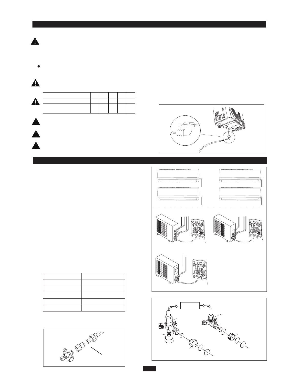
INSTALLING THE OUTDOOR UNIT INSTALLER
Location
Use bolts to secure the unit to a flat, solid floor.
When mounting the unit on a wall or the roof, make
sure the support is firmly secured so that it cannot
move in the event of intense vibrations or a strong
wind.
Do not install the outdoor unit in pits or air vents
Installing the pipes
Use suitable connecting pipes and equipment for
the refrigerant R32.
Models(ft)
Max. connection pipe length
Max. connection pipe length
(Simple one indoor unit)
18K 24K
131 196 262 262
65
The refrigerant pipes must not exceed the
maximum heights 49ft(24K), 82ft(30K).
Wrap all the refrigerant pipes and joints.
Tighten the connections using two wrenches working in opposite directions.
30K 36K 42K
65 82 82 82
328
Caution: Installation Must be Performed in
Accordance with the NEC/CEC by Authorized
Personnel Only.
Install the drain fitting and the drain hose
(for model with heat pump only)
Condensation is produced and flows from the outdoor unit when the appliance is operating in the
heating mode. In order not to disturb neighbours
and to respect the environment,install a drain fitting
and a drain hose to channel the condensate water.
Install the drain fitting and rubber washer on the
outdoor unit chassis and connect a drain hose to it
as shown in the figure.
BLEEDING INSTALLER
Humid air left inside the refrigerant circuit can cause compressor malfunction. After having connected the indoor
and outdoor units, bleed the air and humidity from the
refrigerant circuit using a vacuum pump.
(1) Unscrew and remove the caps from the 2-way and 3-
way valves.
(2) Unscrew and remove the cap from the service valve.
(3) Connect the vacuum pump hose to the service valve.
(4) Operate the vacuum pump for 10-15 minutes until an
absolute vacuum of 10 mm Hg has been reached.
(5) With the vacuum pump still in operation, close the
low-pressure knob on the vacuum pump coupling.
Stop the vacuum pump.
(6) Open the 2-way valve by 1/4 turn and then close it
after 10 seconds. Check all the joints for leaks using
liquid soap or an electronic leak device.
(7) Turn the body of the 2-way and 3-way valves. Discon nect the vacuum pump hose.
(8) Replace and tighten all the caps on the valves.
Diameter
1/4''
3/8''
5/8''
1/2''
3/4''
Twisting moment (ft lb)
11-22
25-29
44-47
33-36
51-55
When the adaptor is required for the connection of indoor
unit and outdoor unit, the method
follows:
of pipe connection as
conversion joint
Service
inlet
(2)Turn
(8) Secure
Refrigerant fluid di
3-w
Vacuum pump Vacuum pump
Vacuum pump
(2)Turn
(8) Secure
2-w
ay valve
(6) Open by 1/4 turn
(7)Turn to open fully
INDOOR
UNIT
rection of fiow
ay valve
(7)Turn to open fully
Valve cap
V
alve cap
(2)Turn
(8) Secure
Connect to the
indoor unit
15
Page 19
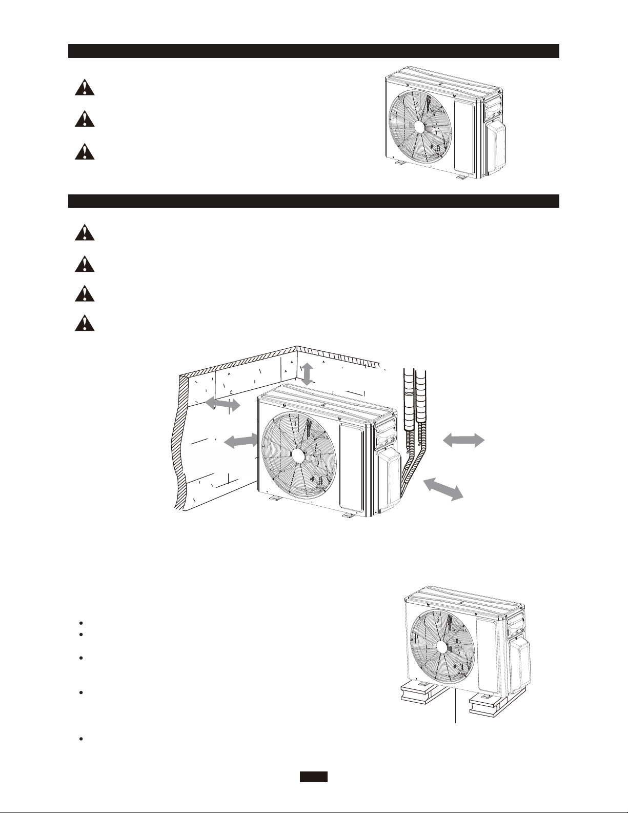
MAINTENANCE
Use suitable instruments for the refrigerant R32.
Do not use any other refrigerant than R32.
Do not use mineral oils to clean the unit.
INSTALLER
INSTALLATION DIMENSION DIAGRAM
The installation must be done by trained and qualified service personnel with reliability according to this
manual.
Contact service center before installation to avoid the malfunction due to unprofessional installation.
When picking up and moving the units, you must be guided by trained and qualified person.
Ensure that the recommended space is left around the appliance.
19"
or more Space
to the cover
11"
or above
Space to the cover
or above
78"
outlet side)
(Air
11"
(Air inlet side)
INSTALLER
or above
19"
or above
space
to
wall
Fix the support of outdoor unit (select it according to the actual installation situation)
1. Select installation location according to the house structure.
2. Fix the support of outdoor unit on the selected location with expansion
screws.
NOTICE:
Take sufficient protective measures when installing the outdoor unit.
Make sure the support can withstand at least four times of the unit
weight.
The outdoor unit should be installed at least 3cm above the floor in
order to install drain joint. (for the model with heating tube, the
installation height should be no less than 20cm.)
For the unit with cooling capacity of 2300W ~ 5000W, 6 expansion
screws are needed; for the unit with cooling capacity of 6000W~
8000W, 8 expansion screws are needed; for the unit with cooling
capacity of 10000W~16000W, 10 expansion screws are needed.
As for the shape of drainage joint, please refer to the current product.
Do not install the drainage joint in the severe cold area. Otherwise,
it will be frosted and then cause malfunction.
16
at least 1 3/16"above the floor
Page 20
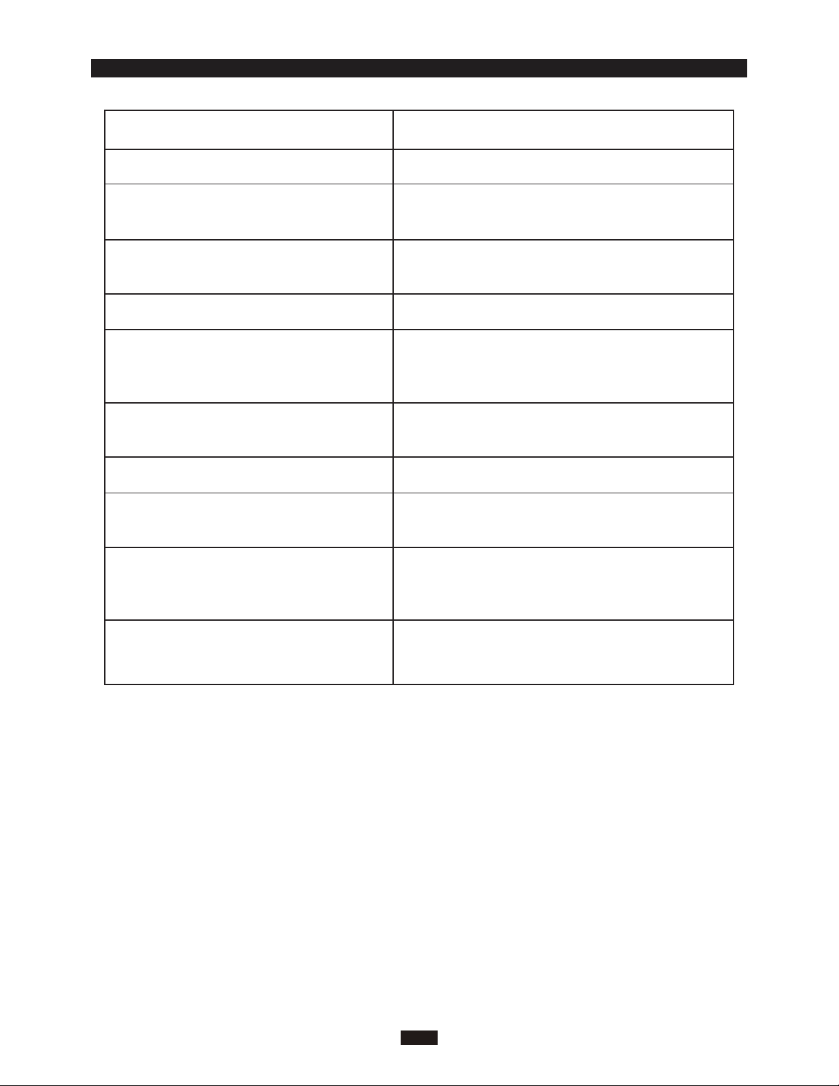
CHECK AFTER INSTALLATION INSTALLER
Check Ltems
Is the installation reliable?
Has the gas leakage been checked?
Is the thermal insulation of the unit
sufficient?
Is the drainage smooth?
Does the power supply voltage accord
with the rated voltage specified on the
nameplate?
Are the lines and pipelines correctly
installed?
Has the unit been safely grounded?
Are the models of lines in conformity
with requirements?
Problems Rwing to Lmproper Lnstallation
The unit may drop, vibrate or make noises
May cause unsatisfactory cooling (heating)
effect
May cause condensation and water dropping
May cause condensation and water dropping
The unit may bread down or the components
may be burned out
The unit may bread down or the components
may be burned out
Risk of electrical leakage
The unit may bread down or the components
may be burned out
Are there any obstacles near the air
inlet and outlet of the indoor and outdoor units?
Have the length of refrigerating pipe
and refrigerant charge amount been
recorded?
The unit may bread down or the components
may be burned out
It is not easy to decide the charge amount
of refrigerant.
17
Page 21

SPECIALIST’S MANUAL
INSTALLER
Aptitude requirement for maintenance
man(repairs should be done only be
specialists).
a.
Any person who is involved with working on or
breaking into a refrigerant circuit should hold a
current valid certificate from an industry-accredited
assessment authority,which authorises their competence to handle refrigerants safely in accordance with an industry recognised assessment
specification.
b.
Servicing shall only be performed as recommended by the equipment manufacturer. Maintenance and repair requiring the assistance of other
skilled personnel shall be carried out under the
supervision of the person competent in the use
of flammable refrigerants.
That pipe-work including piping material, pipe
routing, and installation shall include protection
from physical damage in operation and service,
and be in compliance with national and local
codes and standards, such as ASHRAE 15,
ASHRAE 15.2, IAPMO Uniform Mechanical Code,
ICC International Mechanical Code, or CSA B52.
All field joints shall be accessible for inspection
prior to being covered or enclosed.
ƔƔ
Checks to the area
Prior to beginning work on systems containing
flammable refrigerants, safety checks are necessary to ensure that the risk of ignition is mini-
mised. For repair to the refrigerating system, the
following precautions shall be complied with prior
to conducting work on the system.
Work procedure
Work shall be undertaken under a controlled
procedure so as to minimise the risk of a flammable gas or vapour being present while the work is
being performed.
Ɣ
General work area
All maintenance staff and others working in the
local area shall be instructed on the nature of
work being carried out. Work in confined spaces
shall be avoided.
Ɣ
Checking for presence of refrigerant
The area shall be checked with an appropriate
refrigerant detector prior to and during work, to
ensure the technician is aware of potentially toxic
or flammable atmospheres. Ensure that the leak
detection equipment being used is suitable for use
with all applicable refrigerants, i.e. non-sparking
adequately sealed or intrinsically safe.
Ɣ
Presence of fire extinguisher
If any hot work is to be conducted on the refrigerating equipment or any associated parts, appropriate fire extinguishing equipment shall be available to hand. Have a dry powder or CO2 fire
extinguisher adjacent to the charging area.
Ɣ
No ignition sources
No person c
erating system which involves exposing any pipe
work shall use any sources of ignition in such a
manner that it may lead to the risk of fire or explosion. All possible ignition sources, including cigarette smoking, should be kept sufficiently far away
from the site of installation, repairing, removing
and disposal, during which refrigerant can possibly be released to the surrounding space. Prior to
work taking place, the area around the equipment
is to be surveyed to make sure that there are no
flammable hazards or ignition risks. "No Smoking"
signs shall be displayed.
Ɣ
Ventilated area
Ensure that the area is in the open or that it is
adequately ventilated before breaking into the
system or conducting any hot work. A degree of
ventilation shall continue during the period that
the work is carried out. The ventilation should
safely disperse any released refrigerant and preferably expel it externally into the atmosphere.
Ɣ
Checks to the refrigerating equipment
Where electrical components are being changed,
they shall be fit for the purpose and to the correct
specification. At all times the manufacturer's maintenance and service guidelines shall be followed.
If in doubt, consult the manufacturer's technical
department for assistance.
The following checks shall be applied to installations using flammable refrigerants:
–
the actual refrigerant charge is in accordance
with the room size within which the refrigerant
containing parts are installed;
– the ventilation machinery and outlets are operating adequately and are not obstructed;
– if an indirect refrigerating circuit is being used,
the secondary circuit shall be checked
presence of refrigerant;
– marking to the equipment continues to be visible
,
and legible. Markings and signs that are illegible
shall be corrected;
–
refrigerating pipe or components are installed in
a position where they are unlikely to be ex
to any
containing components, unless the components
are constructed of materials which are inher
arrying out work in relation to a refrig-
substance which may corrode refrigerant
for the
posed
ently
18
Page 22

SPECIALIST’S MANUAL
INSTALLER
resistant to being corroded or are suitably protected against being so corroded.
Ɣ
Checks to electrical devices
Repair and maintenance to electrical components
shall include initial safety checks and component
inspection procedures. If a fault exists that could
compromise safety, then no electrical supply shall
be connected to the circuit until it is satisfactorily
dealt with. If the fault cannot be corrected immediately but it is necessary to continue operation, an
adequate temporary solution shall be used. This
shall be reported to the owner of the equipment so
all parties are advised.
Initial safety checks shall include:
– that capacitors are discharged: this shall be
done in a safe manner to avoid possibility
sparking;
–
that no live electrical components and wiring are
exposed while charging, recovering or purging
system;
–
that there is continuity of earth bonding.
Ɣ
Repairs to sealed components
Sealed electrical components shall be replaced.
Ɣ
Repair to intrinsically safe components
Intrinsically safe components must be replaced.
Ɣ
Cabling
Check that cabling will not be subject to wear,
corrosion, excessive pressure, vibration, sharp
edges or any other adverse environmental effects.
The check shall also take into account the effects
of aging or continual vibration from sources such
as compressors or fans.
Ɣ
Detection of flammable refrigerants
Under no circumstances shall potential sources of
ignition be used in the searching for or detection
of refrigerant leaks. A halide torch (or any other
detector using a naked flame) shall not be used.
The following leak detection methods are deemed
acceptable for all refrigerant systems.
Electronic leak detectors may be used to detect
refrigerant leaks but, in the case of flammable
refrigerants, the sensitivity may not be adequate,
or may need re-calibration. (Detection equipment
shall be calibrated in a refrigerant-free area.)
Ensure that the detector is not a potential source
of ignition and is suitable for the refrigerant used.
Leak detection equipment shall be set at a
percentage of the LFL of the refrigerant and shall
be calibrated to the refrigerant employed, and the
appropriate percentage of gas (25% maximum) is
confirmed.
Leak detection fluids are also suitable for use with
of
the
most refrigerants but the use of detergents containing chlorine shall be avoided as the chlorine
may react with the refrigerant and corrode the
copper pipe-work.
NOTE: Examples of leak detection fluids are
–
bubble method,
– fluorescent method agents.
If a leak is suspected, all naked flames
removed/extinguished.
If a leak
brazin
from the system, or isol
valves)
leak. Removal of refrigerant shall be according to
clause Remov
Ɣ
Removal and evacuation
When breaking into the refrigerant circuit to make
repairs – or for any other purpose –conventional
procedures shall be used. However, for flammable
refrigerants it is important that best practice be
followed, since flammability is a consideration.
The following procedure shall be adhered to:
–
national regulations;
The refrigerant charge shall be recovered into the
correct recovery cylinders if venting is not allowed
by local and national codes. For appliances containing flammable refrigerants, the system shall be
purged with oxygen-free nitrogen to render the
appliance safe for flammable refrigerants. This
process might need to be repeated several times.
Compressed air or oxygen shall not be used for
purging refrigerant systems.
For appliances containing flammable refrigerants,
refrigerants purging shall be achieved by breaking
the vacuum in the system with oxygen-free nitrogen and continuing to fill until the working pressure is achieved, then venting to atmosphere, and
finally pulling down to a vacuum (optional for A2L).
This process shall be repeated until no refrigerant
is within the system (optional for A2L). When the
final oxygen-free nitrogen charge is used, the
system shall be vented down to atmospheric pressure to enable work to take place.
The outlet for the vacuum pump shall not be close
to any potential ignition sources, and ventilation
shall be available.
age of refrigerant is found which require
g, all of the refrigerant shall be recove
ated (b
in a part of the system remote from the
al and evacuation.
safely remove refrigerant following local and
–
evacuate;
–
purge the circuit with inert gas (optional for A2L);
–
evacuate (optional for A2L);
–
continuously flush or purge with inert gas when
using flame to open circuit; and
–
open the circuit.
y means of shut off
shall be
s
red
19
Page 23
SPECIALIST’S MANUAL
INSTALLER
Ɣ
Charging procedures
In addition to conventional charging procedures,
the following requirements shall be followed.
– Ensure that contamination of different refrigerants does not occur when using charging equipment Hoses or lines shall be as short as possible
to minimise the amount of refrigerant contained in
them.
–
Cylinders shall be kept in an appropriate position according to the instructions.
–
Ensure that the refrigerating system is earthed
prior to charging the system with refrigerant.
–
Label the system when charging is complete (if
not already).
Extreme care shall be taken not to overfill the
–
refrigerating system.
Prior to recharging the system, it shall be pressure-tested with the appropriate purging gas.
system shall be leak-tested on completion of
chargin
leak test shall be carried out prior to leav
site.
Ɣ
Decommissioning
Before carrying out this procedure, it is essential
that the technician is completely familiar with the
equipment and all its detail. It is recommended
good practice that all refrigerants are recovered
safely. Prior to the task being carried out, an oil
and refrigerant sample shall be taken in case
analysis is required prior to re-use of recovered
refrigerant. It is essential that electrical power is
available before the task is commenced.
a)
b)
c)
d)
e)
f)
g)
g but prior to commissioning. A follow up
ing the
Become familiar with the equipment an
operation.
Isolate system electrically.
Before attempting the procedure, ensure that:
mec
hanical handling equipment is available,
if required, for handling refrigerant cylinders;
all personal protective equipment is available
and being used correctly;
the recovery process is supervised at all
times by a competent person;
recovery equipment and cylinders conform to
the appropriate standards.
Pump down refrigerant system, if possible.
If a vacuum is not possible
that refrigerant can be removed from various
parts of the system.
Make sure that cylinder is situated on the
scales before recovery takes place.
Start the recovery machine and operate in
accordance with instructions.
, make a manifold so
The
d its
h)
Do not overfill cylinders. (No more than 80%
volume liquid charge).
i)
Do not exceed the maximum working pressure
of the cylinder, even temporarily.
j)
When the cylinders have been filled correctly
and the process completed, make sure that the
cylinders and the equipment are removed from
site promptly and all isolation valves on the
equipment are closed off.
k)
Recovered refrigerant shall not be charged into
another refrigerating system unless it has been
cleaned and checked.
ƔƔ
Labelling
Equipment shall be labelled stating that it has
been de-commissioned and emptied of refrigerant.
The label shall be dated and signed. For appliances containing flammable refrigerants, ensure that
there are labels on the equipment stating the
equipment contains flammable refrigerant.
Recovery
When removing refrigerant from a system, either
for servicing or decommissioning, it is recommended good practice that all refrigerants are
removed safely.
When transferring refrigerant into cylinders,
ensure that only appropriate refrigerant recovery
cylinders are employed. Ensure that the correct
number of cylinders for holding the total system
charge are available. All cylinders to be used are
designated for the recovered refrigerant and
labelled for that refrigerant (i.e. special cylinders
for the recovery of refrigerant). Cylinders shall be
complete with pressure-relief valve and associated shut-off valves in good working order. Empty
recovery cylinders are evacuated and, if possible,
cooled before recovery occurs.
The recovery equipment shall be in good working
order with a set of instructions concerning the
equipment that is at hand and shall be suitable
for the recovery of the flammable refrigerant. If in
doubt, the manufacturer should be consulted. In
addition, a set of calibrated weighing scales shall
be available and in good working order. Hoses
shall be complete with leak-free disconnect couplings and in good condition.
The recovered refrigerant shall be processed
according to local legislation in the correct recovery cylinder, and the relevant waste transfer note
arranged. Do not mix refrigerants in recovery
units and especially not in cylinders.
If compressors or compressor oils are to be
removed, ensure that they have been evacuated
20
Page 24

SPECIALIST’S MANUAL
to an acceptable level to make certain that flammable refrigerant does not remain within the
lubricant. The compressor body shall not be
heated by an open flame or other ignition sources
to accelerate this process. When oil is drained
from a system, it shall be carried out safely.
Transportation, marking and storage for units
Transport of equipment containing flammable
refrigerants.
Attention is drawn to the fact that additional transportation regulations may exist with respect to
equipment containing flammable gas. The maximum number of pieces of equipment or the configuration of the equipment permitted to be transported together will be determined by the applicable
transport regulations.
Marking of equipment using signs
Signs for similar appliances used in a work area
are generally addressed by local regulations and
give the minimum requirements for the provision of
safety and/or health signs for a work location.
All required signs are to be maintained and
employers should ensure that employees receive
suitable and sufficient instruction and training on the
meaning of appropriate safety signs and the
actions that need to be taken in connection with
these signs.
The effectiveness of signs should not be diminished by too many signs being placed together.
Any pictograms used should be as simple as
possible and contain only essential details.
Disposal of equipment using flammable
refrigerants
See national regulations.
Storage of equipment/appliances
The storage of the appliance should be in accordance with the applicable regulations or instructions, whichever is more stringent.
Avoid other heat sources or direct sun light.
Avoid a place where is possible for inflammable
gas to leak out.
Storage of packed (unsold) equipment
Storage package protection should be constructed such a way that mechanical damage to the
equipment inside the package will not cause a leak
of the REFRIGERANT CHARGE.
The maximum number of pieces of equipment
permitted to be stored together will be determined
by local regulations.
INSTALLER
21
Page 25
GREE ELECTRIC APPLIANCES, INC. OF ZHUHAI
Add: West Jinji Rd, Qianshan, Zhuhai,Guangdong, China, 519070
Tel: (+86-756) 8522218
Fax: (+86-756) 8669426
E-mail: [email protected]
Web: www.gree.com
600005068089
CAT No. 09122024
 Loading...