

Gree GWHD(18)ND3CO, GWHD(36)ND3AO, GWHD(24)ND3CO, GWHD(30)ND3CO, GWHD(42)ND3AO User Manual
evo +MULTI
DUCTLESS INVERTER
HEAT PUMP
INSTALLATION MANUAL
Models:
GWHD(18)ND3CO
GWHD(24)ND3CO
GWHD(30)ND3CO
GWHD(36)ND3AO
GWHD(42)ND3AO
Thank you for choosing a
Gree Multi Ductless Heat Pump
for your customer.
Please read this installation manual carefully before installing and
starting up the Multi System. Take a moment to fill out the product
and installation form on the back cover. Retain both the manual
and installation record for future reference.
Contents
•
Safety Precautions
2
•
System Requirements
4
•
Suggested Tools
5
•
Site Instructions
6
•
Dimensions
7
•
Indoor Unit
9
•
Outdoor Unit
12
•
Refrigerant Piping
13
•
Power and Wiring
16
•
Vacuum Testing
19
•
Start-up
21
•
Troubleshooting
22
1
2
SAFETY PRECAUTIONS
Please read the following before installation.
Recognize safety information. This is the safety-alert symbol. When you see this
symbol on the unit and in instructions or manuals, be alert to the potential for personal
injury. Understand these signal words: DANGER, WARNING, and CAUTION. These
words are used with the safety-alert symbol.
DANGER identifies the most serious hazards which will result in severe personal injury
or death.
WARNING signifies hazards which could result in personal injury or death.
CAUTION is used to identify unsafe practices which may result in minor personal
injury or product and property damage.
NOTE is used to highlight suggestions which will result in enhanced installation,
reliability, or operation.
NOTE: Your actual heat pump system and related devices may differ from the images
shown in this manual.
This appliance is not intended for use by children without responsible adult supervision.
Proper care should be taken to ensure safety.
Heat pumps, air conditioners & heating equipment should be installed, started up, and
serviced only by qualified installers and service technicians. Air conditioning, heat pumps
and refrigeration systems are hazardous due to high voltage electrical components, high
refrigerant pressures, and moving parts.
WARNING
SAFETY PRECAUTIONS
• The unit should be installed and serviced only by trained, qualified installers and service
mechanics. Untrained personnel can perform basic maintenance functions such as
cleaning coils. All other operations should be performed by trained service personnel.
• Owner should be cautioned that children should not play with the appliance.
ELECTRICAL SHOCK HAZARD
Failure to follow this warning could result in personal injury or death.
• Before installing, servicing or modifying the system, the main electrical disconnect switch
must be in the OFF position. There may be more than one disconnect switch. Lock out
and tag all switches with a warning label.
General Safety Precautions
• A dedicated power supply circuit should be used in accordance with local electrical
safety regulations and National Electrical Codes (NEC).
• Ensure that the entire system is reliably grounded.
• Use proper size circuit breaker to protect equipment against short circuit and
overload conditions.
• The system must be positioned at least 5 feet from combustive surfaces.
• Observe all local codes and regulations.
INSTALLATION SITE INSTRUCTIONS
Proper installation site is vital for correct and reliable operation of the system.
Avoid the following installation locations :
• Strong heat sources, vapors, flammable gas or volatile liquids.
• High-frequency electro-magnetic waves, generated by radio equipment, welders
or medical equipment.
3
WARNING
CAUTION
5
• Standard Wrench
• Adjustable/Crescent Wrench
• Torque Wrench
• Hex Keys or Allen Wrenches
• Drill & Drill Bits
• Hole Saw
• Pipe Cutter
• Screw drivers (Phillips & Flat blade)
• Manifold and Gauges
• Level
• R410A Flaring Tool
• Clamp on Amp Meter
• Vacuum Pump
• Safety Glasses
• Work Gloves
• Refrigerant Scale
• Micron Gauge
SUGGESTED TOOLS

6
INSTALLATION SITE INSTRUCTIONS
Step 1
Installation Site of Indoor Unit
Select a site that allows for the following:
• Ensure the installation complies with the installation minimum dimensions and meets the
minimum and maximum connecting piping length and maximum change in elevation.
•
Air inlet and outlet will be clear of obstructions, ensuring proper airflow throughout the room.
• Condensate can be easily and safely drained.
• All connections can be easily made to outdoor unit.
• Indoor unit is out of reach of children.
• A wall strong enough to withstand the full weight and vibration of the unit.
• Filter can be easily accessed for cleaning.
• Leave enough free space to allow access for routine maintenance.
• Install at least 10 ft. (3 m) away from the antenna of TV set or radio. Operation of the air
conditioner may interfere with radio or TV reception in areas where reception is weak.
An amplifier may be required for the affected device.
• Do not install in a laundry room or by a swimming pool.
• Determine if condensate pumps are required to properly drain condensate water from
the indoor units.
Installation Site of Outdoor Unit
Select a site that allows for the following:
• Outdoor location meets all minimum installation distances defined in the Installation
Dimensions section.
• Sound from outdoor unit will not annoy neighbors.
• All connections can be easily made to indoor unit.
• Air inlet and outlet will be clear of obstructions to ensure proper airflow.
• Wall or roof is strong enough to withstand the full weight and vibration of the outdoor
unit (for wall or roof installation only).
• Outdoor unit is out of reach of children and does not obstruct walkways.
• Outdoor unit is not exposed to direct sunlight or strong wind.
• Maintenance and repairs can be easily performed on the outdoor unit.
• Ensure the installation complies with the minimum and maximum connecting piping
length and maximum change in elevation criteria.

8
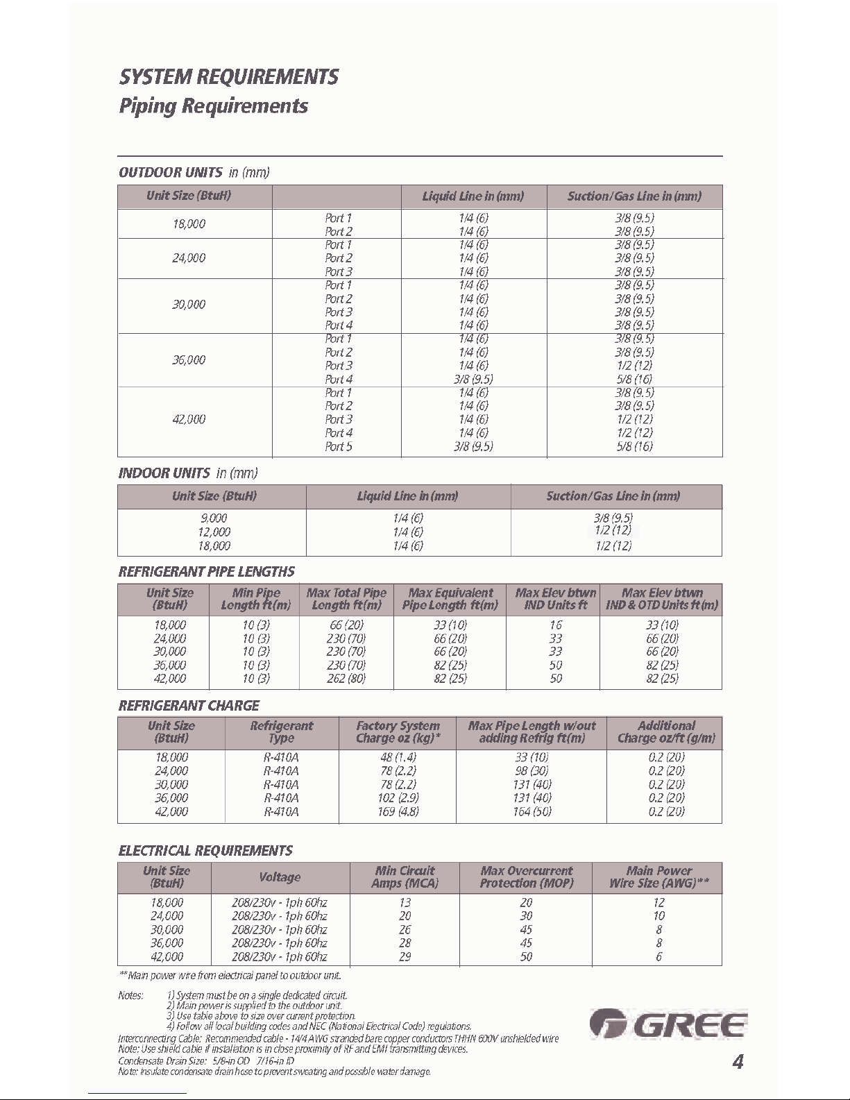
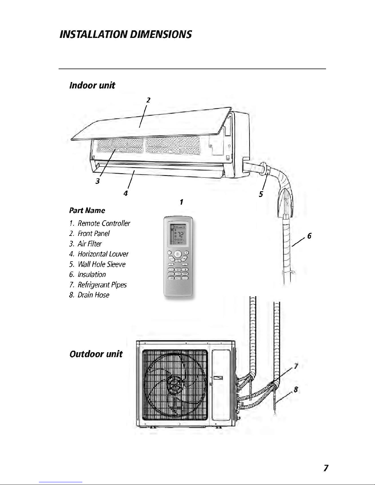
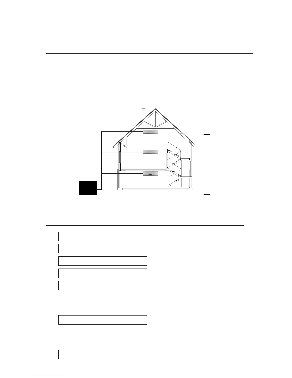
INSTALLATION DIMENSIONS
Minimum indoor clearances
Minimum outdoor clearances
Outdoor Unit
Minimum Distances
in (mm)
A 20 (500)
B 24 (610)
C 78 (2000)
D 12 (305)
E 20 (500)
5 in
(0.13m)
5 in
(0.13m)
6 ft (1.8m)
6 in (0.15m)
Air inlet
Air outlet
Ceiling
Floor
INSTALLATION OF INDOOR UNIT
Step 2
Piping Design and Layout
The piping design and layout are critical factors for the overall performance and reliability of the
system. Find the desired locations for each indoor unit and the outdoor unit.
Measure and record the piping length (L1,L2, L3….Ln) from the outdoor unit to each indoor unit.
NOTE: Min. refrigerant line length between the indoor and outdoor units is 10 ft. (3 m).
L1=
L2=
L3=
L4=
L5=
Find the indoor units with the greatest vertical distance from the outdoor unit. Measure the maximum
vertical height (H1) from the bottom of the outdoor unit to the bottom of the highest mounted indoor units.
H1=
Find the two indoor units with the greatest vertical distance from each other. Measure the maximum
vertical height (H2) between those two indoor units from bottom of one unit to bottom of the other unit.
H2=
9
L2
Ln
L1
H1
H2
 Loading...