

Gree GWHD(18)NK3FOGWHD(24)NK3FOGWHD(24)NK3GO, GWHD(42)NK3AO, GWHD(28)NK3FO, GWHD(36)NK3BO Service Manual

Change for Life
Service Manual
Models: GWHD(18)NK3FO
GWHD(24)NK3FO
GWHD(24)NK3GO
GWHD(28)NK3FO
GWHD(36)NK3BO
GWHD(42)NK3AO
(Refrigerant:R410A)
GREE ELECTRIC APPLIANCES,INC.OF ZHUHAI

Table of Contents
Service Manual
Part
1. Summary
2. Specications
: Technical Information
Ⅰ
......................................................................................................................1
..........................................................................................................2
3. Outline Dimension Diagram
4. Refrigerant System Diagram
5. Electrical Part
5.1 Wiring Diagram ...............................................................................................................14
5.2 PCB Printed Diagram .....................................................................................................20
6. Function and Control
Part
: Installation and Maintenance
Ⅱ
.........................................................................................................14
......................................................................................24
7. Notes for Installation and Maintenance
8. Installation Manual
8.1 Electrical Connections ....................................................................................................32
............................................................................................31
.......................................................................1
......................................................................10
....................................................................12
.................................................29
..........................................29
8.2 Installing the Outdoor Unit ..............................................................................................35
8.3 Installation Dimension Diagram ......................................................................................36
8.4 Check after Installation ...................................................................................................37
9. Maintenance
9.1 Precautions before Performing Inspection or Repair .....................................................47
9.2 Flashing LED of Indoor/Outdoor Unit and Primary Judgement .....................................48
9.3 Malfunction Checking and Elimination ...........................................................................49
9.4 Maintenance Method for Normal Malfunction .................................................................73
10. Exploded View and Parts List
11. Removal Procedure
Appendix:
Appendix 1: Reference Sheet of Celsius and Fahrenheit ..................................................106
Appendix 2: Conguration of Connection Pipe ...................................................................106
Appendix 3: Pipe Expanding Method .................................................................................107
Appendix 4: List of Resistance for Temperature Sensor ....................................................108
......................................................................................................................106
............................................................................................................47
..............................................................75
.......................................................................................86
Table of Contents
Service Manual
Part
Ⅰ
: Technical Information
1. Summary
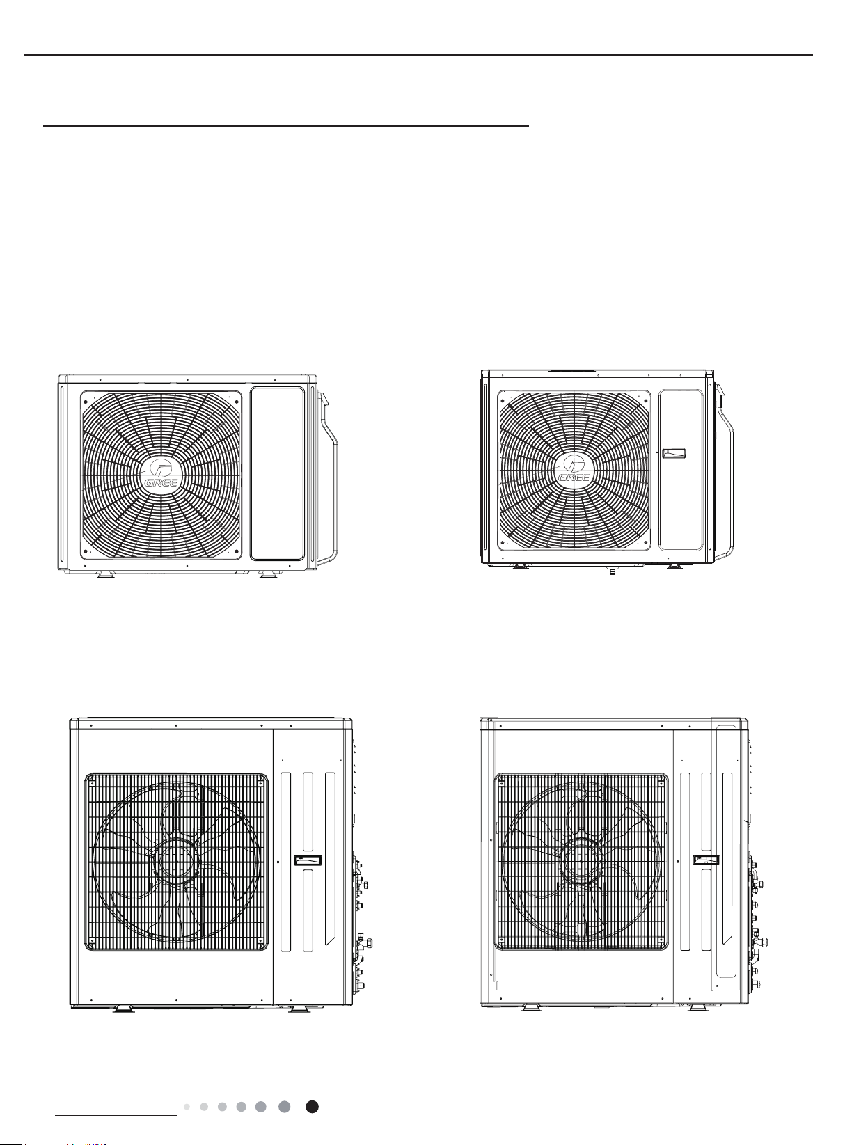
Outdoor Unit
GWHD(18)NK3FO GWHD(24)NK3FO
GWHD(24)NK3GO
GWHD(28) NK3FO
GWHD(42)NK3AOGWHD(36)NK3BO
Technical Information
1
2. Specications
Model GWHD(18)NK3FO
Product Code CB228W03500/CB228W03501
Power
supply
Cooling capacity(max~min) W 5000(2050~6200)
Heating capacity(max~min) W 5600(2500~6650)
Cooling Power Input(max~min) W 1550(500~2550)
Heating Power Input(max~min) W 1550(580~2700)
Cooling Current Input A 6.88
Heating Current Input A 6.88
Rated Power Input W 2700
Rated Current A 11.98
SEER W/W 5.6
SCOP W/W 3.8
Outdoor
Unit
Rated Voltage V~ 220-240V
Rated Frequency Hz 50
Phases 1
Compressor Trademark ZHUHAI LANDA COMPRESSOR CO.,LTD
Compressor Model QXA-B141zF030A
Compressor Refrigerant Oil Type RB68EP
Compressor Type Rotary
L.R.A A /
Compressor Rated Load Amp (RLA) A 7.2
Compressor Power Input W 1440
Compressor Thermal Protector 1NT11L-6233
Throttling Method Electron expansion valve
Cooling Operation Ambient Temperature Range
Heating Operation Ambient Temperature Range
Condenser Material Aluminum Fin-copper Tube
Condenser Pipe Diameter mm Φ7
Rows-Fin Gap(mm) mm 2-1.4
Coil length (l) X height (H) X coil width (L) mm 851X38.1X660
Fan Motor Speed (rpm) (H/M/L) rpm 630
Output of Fan Motor W 60
Fan Motor RLA A /
Fan Motor Capacitor μF /
Air Flow Volume of Outdoor Unit m3/h 3200
Fan Type-Piece Axial-ow
Fan Diameter mm Φ520
Defrosting Method Automatic Defrosting
Climate Type T1
Isolation I
Moisture Protection IP24
Permissible Excessive Operating Pressure for the
Discharge Side
Permissible Excessive Operating Pressure for the
Suction Side
Dimension (WXHXD) mm 963X700X396
Dimension of Package (LXWXH) mm 1026X455X735
Dimension of Package(LXWXH) mm 1029X458X750
Net Weight kg 50
Gross Weight kg 55
efrigerant Charge R410A
Refrigerant Charge kg 1.40
O
C -15~48
O
C -15~24
MPa 4.3
MPa 2.5
Service Manual
2
Technical Information

Service Manual
Cross-sectional Area of Power Cable Conductor mm
2
Recommended Power Cable(Core) N 3
Connection Pipe Connection Method - Flare Connection
Not Additional Gas Connection Pipe Length m 5
Connection Pipe Gas Additional Charge g/m 20
Outdoor
Unit
Outer Diameter of Liquid Pipe(GREE Allocation)
(Metric)
Outer Diameter of Gas Pipe(GREE Allocation)
(Metric)
Connection Pipe Max. Height Distance(indoor and
indoor)
Max. equivalent connection pipe length(outdoor to
last indoor)
mm Φ6
mm Φ9.52
m 5
m 10
Connection Pipe Max. Length Distance(total lenght) m 20
The above data is subject to change without notice; please refer to the nameplate of the unit.
2.50
Technical Information
3
Service Manual
Model GWHD(24)NK3FO GWHD(24)NK3GO
Product Code CB228W03301 CB228W03401/CB228W03400
Power
supply
Rated Voltage V~ 220-240V 220-240V
Rated Frequency Hz 50 50
Phases 1 1
Cooling capacity(max~min) W 7000(2200~10000) 7100(2200~10000)
Heating capacity(max~min) W 7700(2600~11000) 8500(3600~11000)
Cooling Power Input(max~min) W 2460(650~4550) 2400(650~4550)
Heating Power Input(max~min) W 2560(980~3950) 2350(980~3950)
Cooling Current Input A 10.91 10.91
Heating Current Input A 11.36 11.36
Rated Power Input W 4550 4550
Rated Current A 20.19 20.19
SEER W/W 5.1 5.1
SCOP W/W 3.8 3.8
Compressor Trademark
ZHUHAI LANDA
COMPRESSOR CO.,LTD
ZHUHAI LANDA
COMPRESSOR CO.,LTD
Compressor Model QXAS-D23zX090B QXAS-D23zX090B
Compressor Refrigerant Oil Type RB68EP RB68EP
Compressor Type Rotary Rotary
L.R.A A / /
Compressor Rated Load Amp (RLA) A 11.5 11.5
Compressor Power Input W 2550 2550
Compressor Thermal Protector 1NT11L-6233 1NT11L-6233
Throttling Method Electron expansion valve Electron expansion valve
Cooling Operation Ambient Temperature Range
Heating Operation Ambient Temperature Range
O
C -15~48 -15~48
O
C -15~24 -15~24
Condenser Material Aluminum Fin-copper Tube Aluminum Fin-copper Tube
Condenser Pipe Diameter mm Φ7 Φ7
Rows-Fin Gap(mm) mm 2-1.4 2-1.4
Coil length (l) X height (H) X coil width (L) mm 982.2X38.1X748 982.2X38.1X748
Fan Motor Speed (rpm) (H/M/L) rpm 710 710
Output of Fan Motor W 90 90
Outdoor
Unit
Fan Motor RLA A / /
Fan Motor Capacitor μF / /
Air Flow Volume of Outdoor Unit m3/h 4000 4000
Fan Type-Piece Axial-ow Axial-ow
Fan Diameter mm Φ552 Φ552
Defrosting Method Automatic Defrosting Automatic Defrosting
Climate Type T1 T1
Isolation I I
Moisture Protection IP24 IP24
Permissible Excessive Operating Pressure for the
Discharge Side
Permissible Excessive Operating Pressure for the
Suction Side
MPa 4.3 4.3
MPa 2.5 2.5
Dimension (WXHXD) mm 1001X790X427 1001X790X427
Dimension of Package (LXWXH) mm 1080X485X840 1080X485X840
Dimension of Package(LXWXH) mm 1083X488X855 1083X488X855
Net Weight kg 68 69
Gross Weight kg 73 74
efrigerant Charge R410A R410A
Refrigerant Charge kg 2.00 2.20
4
Technical Information
Service Manual
Cross-sectional Area of Power Cable Conductor mm
2
2.50 2.50
Recommended Power Cable(Core) N 3 3
Connection Pipe Connection Method - Flare Connection Flare Connection
Not Additional Gas Connection Pipe Length m 5 5
Connection Pipe Gas Additional Charge g/m 20 20
Outdoor
Unit
Outer Diameter of Liquid Pipe(GREE Allocation)
(Metric)
Outer Diameter of Gas Pipe(GREE Allocation)
(Metric)
Connection Pipe Max. Height Distance(indoor and
indoor)
Max. equivalent connection pipe length(outdoor to
last indoor)
mm Φ6 Φ6
mm Φ9.52 Φ9.52
m 5 10
m 10 20
Connection Pipe Max. Length Distance(total lenght) m 20 60
The above data is subject to change without notice. Please refer to the nameplate of the unit.
Technical Information
5
Model GWHD(28)NK3FO
Product Code CB228W03600/CB228W03601
Power
supply
Rated Voltage V~ 220-240V
Rated Frequency Hz 50
Phases 1
Cooling capacity(max~min) W 8000(2200~10000)
Heating capacity(max~min) W 9300(2800~11000)
Cooling Power Input(max~min) W 2490(650~4550)
Heating Power Input(max~min) W 2580(980~3950)
Cooling Current Input A 11.05
Heating Current Input A 11.45
Rated Power Input W 4550
Rated Current A 20.19
SEER W/W 5.1
SCOP W/W 3.8
Compressor Trademark ZHUHAI LANDA COMPRESSOR CO.,LTD
Compressor Model QXAS-D23zX090B
Compressor Refrigerant Oil Type RB68EP
Compressor Type Rotary
L.R.A A /
Compressor Rated Load Amp (RLA) A 11.5
Compressor Power Input W 2550
Compressor Thermal Protector 1NT11L-6233
Throttling Method Electron expansion valve
Cooling Operation Ambient Temperature Range
Heating Operation Ambient Temperature Range
O
C -15~48
O
C -15~24
Condenser Material Aluminum Fin-copper Tube
Condenser Pipe Diameter mm Φ7
Rows-Fin Gap(mm) mm 2-1.4
Coil length (l) X height (H) X coil width (L) mm 982.2X38.1X748
Fan Motor Speed (rpm) (H/M/L) rpm 710
Output of Fan Motor W 90
Outdoor
Unit
Fan Motor RLA A /
Fan Motor Capacitor μF /
Air Flow Volume of Outdoor Unit m3/h 4000
Fan Type-Piece Axial-ow
Fan Diameter mm Φ552
Defrosting Method Automatic Defrosting
Climate Type T1
Isolation I
Moisture Protection IP24
Permissible Excessive Operating Pressure for the
Discharge Side
Permissible Excessive Operating Pressure for the
Suction Side
MPa 4.3
MPa 2.5
Dimension (WXHXD) mm 1001X790X427
Dimension of Package (LXWXH) mm 1080X485X840
Dimension of Package(LXWXH) mm 1083X488X855
Net Weight kg 69
Gross Weight kg 74
efrigerant Charge R410A
Refrigerant Charge kg 2.20
Service Manual
6
Technical Information
Service Manual
Cross-sectional Area of Power Cable Conductor mm
2
Recommended Power Cable(Core) N 3
Connection Pipe Connection Method - Flare Connection
Not Additional Gas Connection Pipe Length m 5
Connection Pipe Gas Additional Charge g/m 20
Outdoor
Unit
Outer Diameter of Liquid Pipe(GREE Allocation)
(Metric)
Outer Diameter of Gas Pipe(GREE Allocation)
(Metric)
Connection Pipe Max. Height Distance(indoor and
indoor)
Max. equivalent connection pipe length(outdoor to
last indoor)
mm Φ6
mm Φ9.52
m 10
m 20
Connection Pipe Max. Length Distance(total lenght) m 70
The above data is subject to change without notice. Please refer to the nameplate of the unit.
2.50
Technical Information
7

Service Manual
Model GWHD(36)NK3BO GWHD(42)NK3AO
Product Code CN860W0131 CN860W0021
Power
supply
Rated Voltage V~ 220-240V 220-240V
Rated Frequency Hz 50 50
Phases 1 1
Cooling capacity(max~min) W 10500(2100~11000) 12100(2100~13600)
Heating capacity(max~min) W 12000(2600~13000) 13000(2600~14000)
Cooling Power Input W 3500 3590
Heating Power Input W 3750 3550
Cooling Current Input A 15.42 16.43
Heating Current Input A 15.20 16.22
Rated Power Input W 4880 5300
Rated Current A 21.65 23.50
SEER W/W 5.5 /
SCOP W/W 3.8 /
MITSUBISHI
ELECTRIC(GUANGZHOU)
COMPRESSOR CO.LTD
Compressor Trademark
ZHUHAI LANDA
COMPRESSOR CO.,LTD
Compressor Model QXAS-D32zX090A TNB306FPGMC
Compressor Refrigerant Oil Type RB68ER PVE(PV50S)
Compressor Type Inverter Rotary Inverter Rotary
L.R.A A / /
Compressor Rated Load Amp (RLA) A 14 13.5
Compressor Power Input W 3300 3010
Compressor Thermal Protector Internal Internal
Throttling Method Electron expansion valve Electron expansion valve
Cooling Operation Ambient Temperature Range
Heating Operation Ambient Temperature Range
O
C -15~48 -15~48
O
C -15~27 -15~27
Condenser Material Copper tube-Aluminum n Copper tube-Aluminum n
Condenser Pipe Diameter mm Φ7.94 Φ7.94
Rows-Fin Gap(mm) mm 2-1.4 2-1.4
Coil length (l) X height (H) X coil width (L) mm 1009.4X38.1X1056 1009.4X38.1X1056
Fan Motor Speed (rpm) (H/M/L) rpm 820 840/620/520
Outdoor
Unit
Output of Fan Motor W 170 140
Fan Motor RLA A / /
Fan Motor Capacitor μF / /
Air Flow Volume of Outdoor Unit m3/h 5200 5500
Fan Type-Piece Axial-ow Axial-ow
Fan Diameter mm Φ570-152 Φ570-152
Defrosting Method Automatic Defrosting Automatic Defrosting
Climate Type T1 T1
Isolation I I
Moisture Protection IPX4 IPX4
Permissible Excessive Operating Pressure for the
Discharge Side
Permissible Excessive Operating Pressure for the
Suction Side
MPa 4.3 4.3
MPa 2.5 2.5
Dimension (WXHXD) mm 1015X440X1103 1015X440X1103
Dimension of Package (LXWXH) mm 1155X490X1220 1155X490X1220
Dimension of Package(LXWXH) mm 1158X493X1235 1158X493X1235
Net Weight kg 94 102
Gross Weight kg 104 112
efrigerant Charge R410A R410A
Refrigerant Charge kg 4.3 4.8
8
Technical Information
Service Manual
Outdoor
Unit
Cross-sectional Area of Power Cable Conductor mm
2
4.0 4.0
Recommended Power Cable(Core) N 3 /
Connection Pipe Connection Method - Flare Connection Flare Connection
Not Additional Gas Connection Pipe Length m 40 50
Connection Pipe Gas Additional Charge g/m 22 22
Outer Diameter of Liquid Pipe(GREE Allocation)
(Metric)1
Outer Diameter of Gas Pipe(GREE Allocation)
(Metric)1
Outer Diameter of Liquid Pipe(GREE Allocation)
(Metric)2
Outer Diameter of Gas Pipe(GREE Allocation)
(Metric)2
Outer Diameter of Liquid Pipe(GREE Allocation)
(Metric)3
Outer Diameter of Gas Pipe(GREE Allocation)
(Metric)3
Outer Diameter of Liquid Pipe(GREE Allocation)
(Metric)4
Outer Diameter of Gas Pipe(GREE Allocation)
(Metric)4
Connection Pipe Max. Height Distance(indoor and
indoor)
Max. equivalent connection pipe length(outdoor to
last indoor)
mm Φ6 Φ6
mm Φ9.52 Φ9.52
Φ6 Φ6
Φ9.52 Φ9.52
Φ6 Φ6
Φ12 Φ12
Φ9.52 Φ6
Φ16 Φ12
m 7.5 7.5
m 20 25
Connection Pipe Max. Length Distance(total lenght) m 70 80
The above data is subject to change without notice. Please refer to the nameplate of the unit.
Technical Information
9
3. Outline Dimension Diagram
(1)Model:GWHD(18)NK3FO
Service Manual
892
963
560
341
700
396
368
(2)Models:GWHD(24)NK3FO GWHD(24)NK3GO GWHD(28) NK3FO
924 370
610
399
790
4271001
10
Unit:mm
Technical Information
Service Manual
950 341
4121022
572
840
378
Unit:mm
1103
360
1103
1015
(3)Model:GWHD(36)NK3BO
(4)Model:GWHD(42)NK3AO
1087
631
1015 360
401
440
Unit:mm
Technical Information
631
4401087
401
Unit:mm
11
4. Refrigerant System Diagram
outdoor
indoor
A1:
C1:C-unit electronic expansion valve D1:D-unit electronic expansion valve
A2:A-unit gas pipe temperature sensor B2:B-unit gas pipe temperature senso
C2:C-unit gas pipe temperature sensor D2:D-unit gas pipe temperature senso
A3:
C3:C-unit liquid pipe temperature sensor D3:D-unit liquid pipe temperature senso
Models:GWHD(18)NK3FO GWHD(24)NK3FO GWHD(24)NK3GO GWHD(28) NK3FO
Service Manual
A heat exchanger
B heat exchanger
C heat exchanger
D heat exchanger
A3
B3
C3
D3
filter
filter
filter
A1
B1
C
D1
filter
A2
B2
1
C2
outdoor heat exchanger
fan
4-way valve
SP
high pressure switch
Note: Not available for 14K/18K
model
discharge silencer
discharge temperature
sensor
inverter compressor
filter
A-unit electronic expansion valve B1:B-unit electronic expansion valve
A-unit liquid pipe temperature sensor B3:B-unit liquid pipe temperature sensor
12
D2
Note: Not available for 18K model
gas -liquid separator
r
r
r
Technical Information
Service Manual
Electronic
Expansion V
Models:GWHD(36)NK3BO,GWHD(42)NK3AO
Liquid Receiver
M
Heat Exchanger
Four-way Valve
Outdoor Unit
Capillary
Oil Separator
Stop Valve
Compressor
Gas/Liquid Separator
alve
Heating
Cooling
Indoor Unit
Heat Exchanger
Heat Exchanger
The outdoor and indoor units start to work once the power is switched on. During the cooling operation, the low
temperature, low pressure refrigerant gas from the heat exchanger of each indoor unit gets together and then is
taken into the compressor to be compressed into high temperature, high pressure gas, which will soon go to
the heat exchanger of the outdoor unit to exchange heat with the outdoor air and then is turned into refrigerant
liquid. After passing through the throttling device, the temperature and pressure of the refrigerant liquid will further
decrease and then go the main valve. After that, it will be divided and go to the heat exchanger of each indoor
unit to exchange heat with the air which needs to be conditioned. Consequently, the refrigerant liquid become low
temperature, low pressure refrigerant gas again. Such a refrigeration cycle goes round and round to achieve the
desired cooling purpose. During the heating operation, the four-way valve is involved to make the refrigeration
cycle run reversely. The refrigerant radiates heat in the heat exchanger of the indoor unit (so do the electric
heating devices) and absorb heat in the heat exchanger of the outdoor unit for a heat pump heating cycle so as to
achieve the desired heating purpose.
Heat Exchanger
Heat Exchanger
Heat Exchanger
Technical Information
13
5. Electrical Part
5.1 Wiring Diagram
●Instruction
Symbol Symbol Color Symbol Symbol Color Symbol Name
WH White GN GREEN COMP Compressor
YE Yellow BN Brown Grouding wire
RD Red BU Blue
YEGN Yellow/Green BK Black
VT Violet OG Orange
Service Manual
●
Outdoor Unit
(1)Model:GWHD(18)NK3FO(CB228W03501)
7(50,1$/
32:(5
/
1
,1'22581,7$
,1'22581,7%
&2035(6625
%$1'+($7(5
%1
%8
<(*1
<(*1
<(*1
%8
%.
%1
3(
%8
%.
%1
3(
%/2&.
;7
7(50,1$/
%/2&.
;7$
7(50,1$/
%/2&.
;7%
(+
3(
%8
%8
%1
/
5'
5'
/
%1
%8
/
<(*1
3(
%1
%21'+($7(5
5'
+($7&
$&/
1
(3(
%27720
(+
+($7%
2)$1
5'
%.
*<
$3
$&/
/
/
:+
1
1
)$
(.9
)$
0DLQ%RDUG$3
%8
%1
%8
)%
(.9
%.
78%($
)%
1
$&/
1
&20,11(5
76(1625
:$<
29&&203
78%(%
%.
:+
%8
8
<(
9
5'
:
&211(&725
:+
:+
57
57
57
97
97
;
<9
:$<9$/9(
/
%8
/
<(
/
5'
:
6$7
29(5/2$'
3527(&725
(;+$867
7(06(1625
2875220
7(06(1625
28778%(
7(06(1625
8
9
&203
&203
3(
14
:$51,1*
0
)$102725
<(*1
3(
:+
%.
4$ <$
57 57
5'
4%
<%
%.
5'%.
5757
287'22581,7
Technical Information
Service Manual
(2)Model:GWHD(18)NK3FO(CB228W03500)
7(50,1$/
32:(5
/
1
&2035(6625
%$1'+($7(5
%/2&.
%1
%8
<(*1
7(50,1$/
%/2&.
%8
%.
%1
<(*1
,1'22581,7$
3(
%8
%.
%1
<(*1
,1'22581,7%
3(
;7
;7$
7(50,1$/
%/2&.
;7%
(+
3(
%8
%8
%1
/
5'
5'
57
:$<
%.
:+
%8
8
<(
9
5'
:
&211(&725
:+
:+
57
57
97
97
;
<9
:$<9$/9(
/
%8
/
<(
/
5'
6$7
29(5/2$'
3527(&725
(;+$867
7(06(1625
2875220
7(06(1625
28778%(
7(06(1625
8
:
9
&203
&203
3(
/
%1
%8
$&/
1
/
$3
(3(
$&/
%8
1
%1
%8
1
1
$&/
1
76(1625
<(*1
3(
%1
+($7&
2)$1
/
%.
/
*<
)$
(.9
:+
)%
(.9
%.
)$
)%
$30DLQ%RDUG
78%($
&20,11(5
29&&203
78%(%
(3)Model:GWHD(24)NK3FO
XT1
XTA
XTB
2
3
2
3
:$51,1*
57 57
<%
%.
U
V
W
287'22581,7
RT1
RT2
RT3
HPS
X1
CONNECTOR
P
U
V
COMP
W
:+
%.
0
<(*1
)$102725
L1
L1
L'
L
N'
N
3(
N1
E(PE)
L4
L4
L3
5'
%. 5'
4%
5757
<$4$
L2
AC-L
L2
N2
N2
N1
LX2-2
LX2-1
Technical Information
Please don't touch any terminal when the voltage of
terminal P(DC+) and N(DC-) at AP1 is higher than
30V to prevent the risk of electrical shock!
M1
TUBE-A
TUBE-B
15
(4)Model:GWHD(24)NK3GO(CB228W03401)
L1
L2
Service Manual
XT1
L
N
2
3
XTA
2
3
XTB
2
3
XTC
Please don't touch any terminal when the voltage of
terminal P(DC+) and N(DC-) at AP1 is higher than
30V to prevent the risk of electrical shock!
L1
N1
L'
AC-L
L2
N2
N'
L4
L4
L4
L3
N1
RT1
RT2
RT3
HPS
P
LX2-2
LX2-1
U
V
W
CONNECTOR
X1
U
V
COMP
W
(5)Model:GWHD(24)NK3GO(CB228W03400)
7(50,1$/%/2&.
%1%.
/
%8
1
<(*1
32:(5
3(
7(50,1$/%/2&.
%8
%.
%1
<(*1
,1'22581,7$
3(
7(50,1$/%/2&.
%8
%.
%1
<(*1
3(
7(50,1$/%/2&.
%8
%.
%1
<(*1
,1'22581,7& ,1'22581,7%
3(
3OHDVHGRQWWRXFKDQ\WHUPLQDOZKHQ
WKHYROWDJHRIWHUPLQDO3'&DQG
1'&DW$3LVKLJKHUWKDQ9WR
SUHYHQWWKHULVNRIHOHFWULFDOVKRFN
/
1
;7
1
;7$
1
;7%
1
;7&
%1
%8
%8
%1
%1
%8
%8
%1
:$51,1*
%1
%8
/
1
),/7(5
/,1(
/
/
/
/2$'
1
(/(&7521,&
(;3$16,21
(.9
:+
2)$1
0
)$102725
$&/
1
$30DLQ%RDUG
/
%.
/
*<
/
:+
/
%8
(/(&7521,&
(/(&7521,&
(;3$16,21
(;3$16,21
9$/9(%9$/9($
9$/9(&
(.9
(.9
5'
%.
)&
)%)$
$30DLQ%RDUG
78%($
:+
3(
<(*1
57
3(
4$
<$
*DV9DOYH
/LTXLG9DOYH
7(036(16257(036(1625
%1
$&/
%8
1
(3(
<(*1
3(
%8
/
5($&725
/
/
2*
:+
/;/;
78%(%
%.
5'%.
57
*DV9DOYH
7(036(1625 7(036(1625
/
$&/
/
1
&20,11(5
1
/;
/;
/
/
5'
%.
57
57
<%4%
/LTXLG9DOYH
%.
76(1625
:+
<(
+33
%8
97
:$<
97
:+
29&&203
%8
8
<(
9
5'
:
&211(&725
:+
;
+($7&
78%(&
5'
5'
%.
57
57
<&4&
*DV9DOYH
/LTXLG9DOYH
7(036(1625 7(036(1625
5'
5'
57
57
57
+36
/
/
/
%8
<(
5'
3
<9
9
:
(;+$867
7(036(1625
2875220
7(036(1625
28778%(
7(036(1625
+LJK
3UHVVXUH
6ZLWFK
:$<
9$/9(
2YHUORDG
3URWHFWRU
6$7
8
&203
<(*1
&203
&RPSUHVVRU
%DQG+HDWHU
3(
3(
16
Technical Information
Service Manual
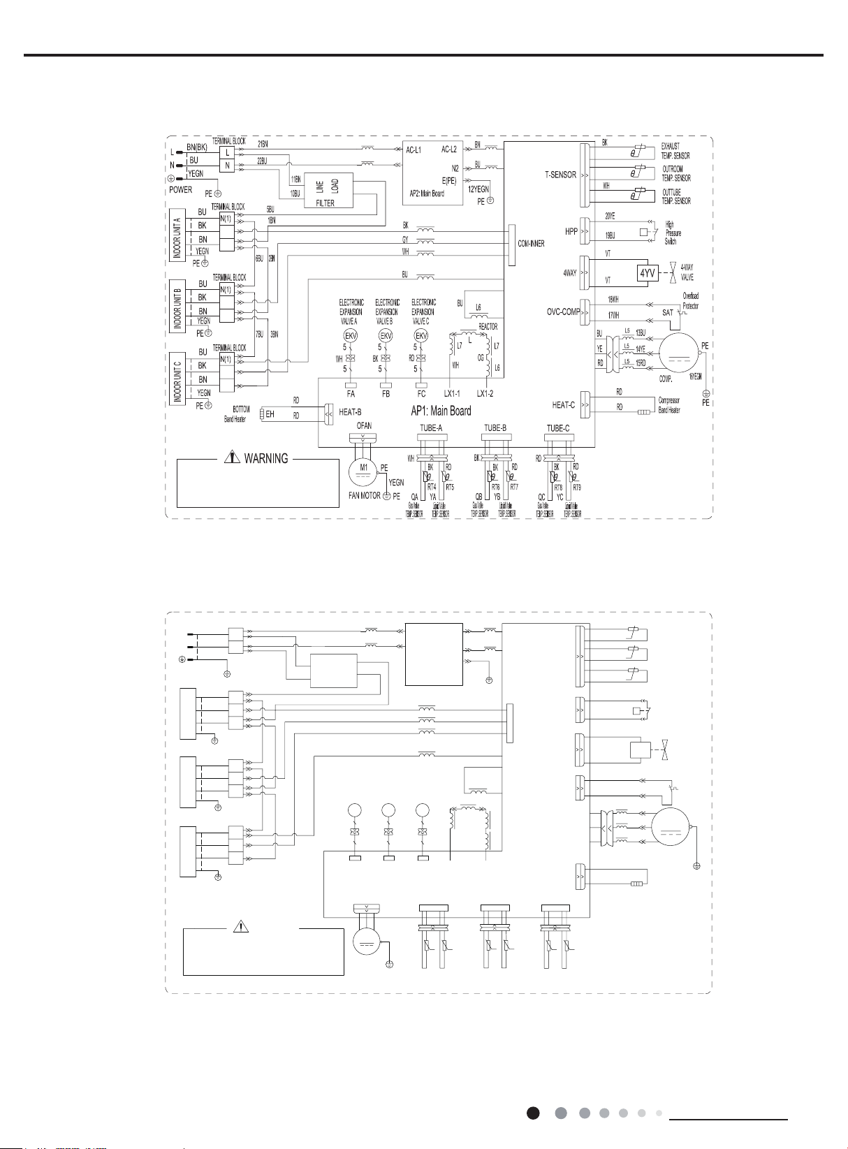
(6)Model:GWHD(28) NK3FO(CB228W03601)(CB228W03600)
XTA
XTB
XTC
XTD
XT1
L1
L1
N1
L'
L
N'
N
2
3
2
3
2
3
2
3
555
E(PE)
L4
L4
L4
L4
L3
5
555 5
L2
AC-L
L2
N2
N2
N1
LX2-2
LX2-1
U
V
W
RT1
RT2
RT3
HPS
X1
CONNECTOR
P
U
V
COMP
W
Technical Information
17
(7)Model:GWHD(36)NK3BO
29(5/2$'3527(&725
6$7
,12873,3(7(036(1625'
,12873,3(7(036(1625&
,12873,3(7(036(1625%
57
57
57
7(50,1$/%2$5'
3,3(7(036(1625
(19,5210(177(036(1625
',6&+$5*(*$67(036(1625
,12873,3(7(036(1625$
57
57
57
57
;7
:$<9$/9(
7(50,1$/%2$5'
&203&5$1.&$6(+($7(5
(+
;7
<9
&2035(6625
,1'8&7$1&(
/
&203
)$102725
/2:35(6685(6:,7&+
0
/3
<.%&
+,*+35(6685(6:,7&+
+3
<.%&
+,*+35(6685(6:,7&+
(/(&7521,&,1)/$7(9$/9(
+3
(.9
1$0(
0$,1%2$5'
$3
6<0%2/
&20321(17
326,7,21',$*5$0
$3
/
;7
Service Manual
;7
;7
;7
;7
3(
(
/
(.9
)$
$&/
/
(.9
(.9
(.9
57
3
6$7
:
:
3
+3
/3
3
+3
.
.
57
57
.
.
76(1625
)&
&20
:
/
)'
29&&203
+33
/33
+35(66
$3
78%($78%(%
2)$1
8
:
9
:
:
:
/
/
/
8
9
:
:
:
&203
/B
%1
/
3(
/
/
<(
/B
%8
/
/B
:+
/
/
/B
78%(&
/
0
/
3(
.
.
.
.
.
.
.
57
57
575757
57
57
)%
1
:
:
/
/
18
:
:
/
;7
32:(5
3(
78%('
:
(+
/ /
:
:
1
1
;7
1
,1'22581,7$
:
:
3(
1
;7
1
,1'22581,7%
:
:
;7
1
3(
1
,1'22581,7&
:
:
;7
1
3(
1
,1'22581,7'
3(
<9
+($7
9
57
Technical Information

Service Manual
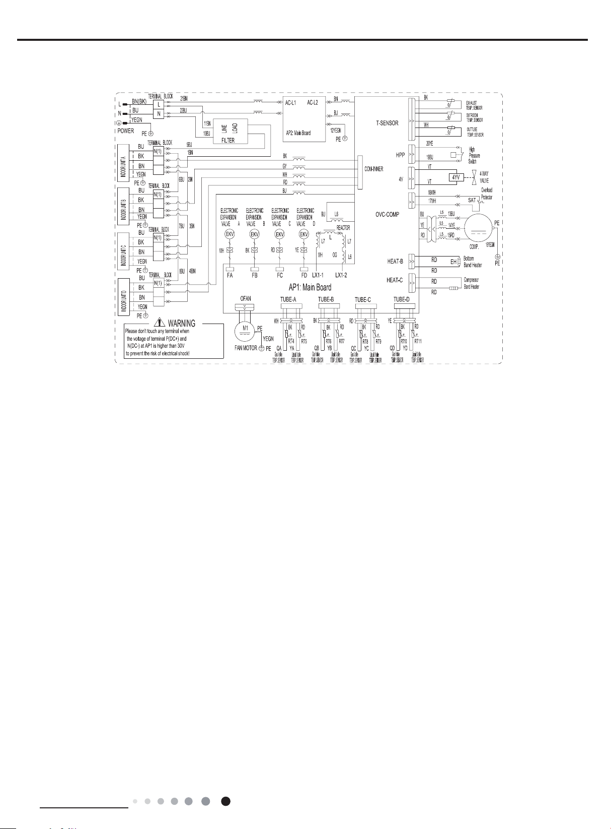
(8) Model:GWHD(42)NK3AO
C
AP
XT1
XT2
XT3
XT4
XT5
XT6
IN/OUT PIPE TEMP. SENSOR E
CAPACITOR FOR FAN MOTOR
OVERLOAD PROTECTOR
C
SAT
RT14/15
EKV1
IN/OUT PIPE TEMP. SENSOR C
IN/OUT PIPE TEMP. SENSOR D
RT12/13
RT10/11
EKV2
IN/OUT PIPE TEMP. SENSOR A
IN/OUT PIPE TEMP. SENSOR B
RT8/9
RT6/7
EKV3EKV4
PIPE TEMP.SENSOR
ENVIRONMENT TEMP.SENSOR
RT1
TERMINAL BOARD 2-6
TERMINAL BOARD 1
DISCHARGE GAS TEMP.SENSOR
RT2
RT3
COMP.CRANK CASE HEATER
INDUCTANCE
COMPRESSOR
L
FAN MOTOR
COMPMLP
4-WAY VALVE
XT2-6
XT1
EH
4YV
ELECTRONIC INFLATE VALVE 1-5
LOW PRESSURE SWITCH
HIGH PRESSURE SWITCH
HP
RT1
EKV5
W25
HP
SAT
W26
LP
θ
20K
MAIN BOARD
AP
EKV1-5
RT2
θ
15K
NAME
SYMBOL
RT3
θ
50K
COMPONENT POSITION DIAGRAM
L
20K
PE
T-SENSOR2
FB
FC
1
3
W16
W15
W14
FA
E1
AC-L
N
PE
W5
FE
FD
HPP
LPP
OVC-COMP
TUBE-ATUBE-B
TUBE-C
WH
OFAN
3
1
BK
YE
7
5
BU
V
W
W20
W21
V
W
3~
COMP
COM
5
7
9
W17
W18
AP
L1_1
BN
L2_1
YE
U
W19
U
PE
W22
L1
L2
BU
L2_2
WH
L1_2
L
TUBE-DTUBE-E
W23
BN
~
M
C
PE
RD
RT6
20K
RT7RT8
θθ
20K
20K
RT9
20K
RT10
θθ θ
20K
RT11RT12
θ
20K
θ
20K
RT13
θ
20K
RT14
θ
20K
RT15
θ
PE
INDOOR UNIT E
EH
4YV
W24
W2
W1
W6
W3
W4
L
N
XT1
POWER
N(1)
XT2
N(1)
W7
2
3
2
3
N(1)
XT3
PE
N(1)
INDOOR UNIT A
W8
W9
2
3
N(1)
XT4
PE
2
3
N(1)
INDOOR UNIT B
W10
W11
3
2
2
N(1)
XT5
PE
3
N(1)
INDOOR UNIT C
W12
W13
3
2
3
2
3
2
N(1)
XT6
PE
2
3
N(1)
INDOOR UNIT D
These circuit diagrams are subject to change without notice, please refer to the one supplied with the unit.
Technical Information
HEAT
4V1
19
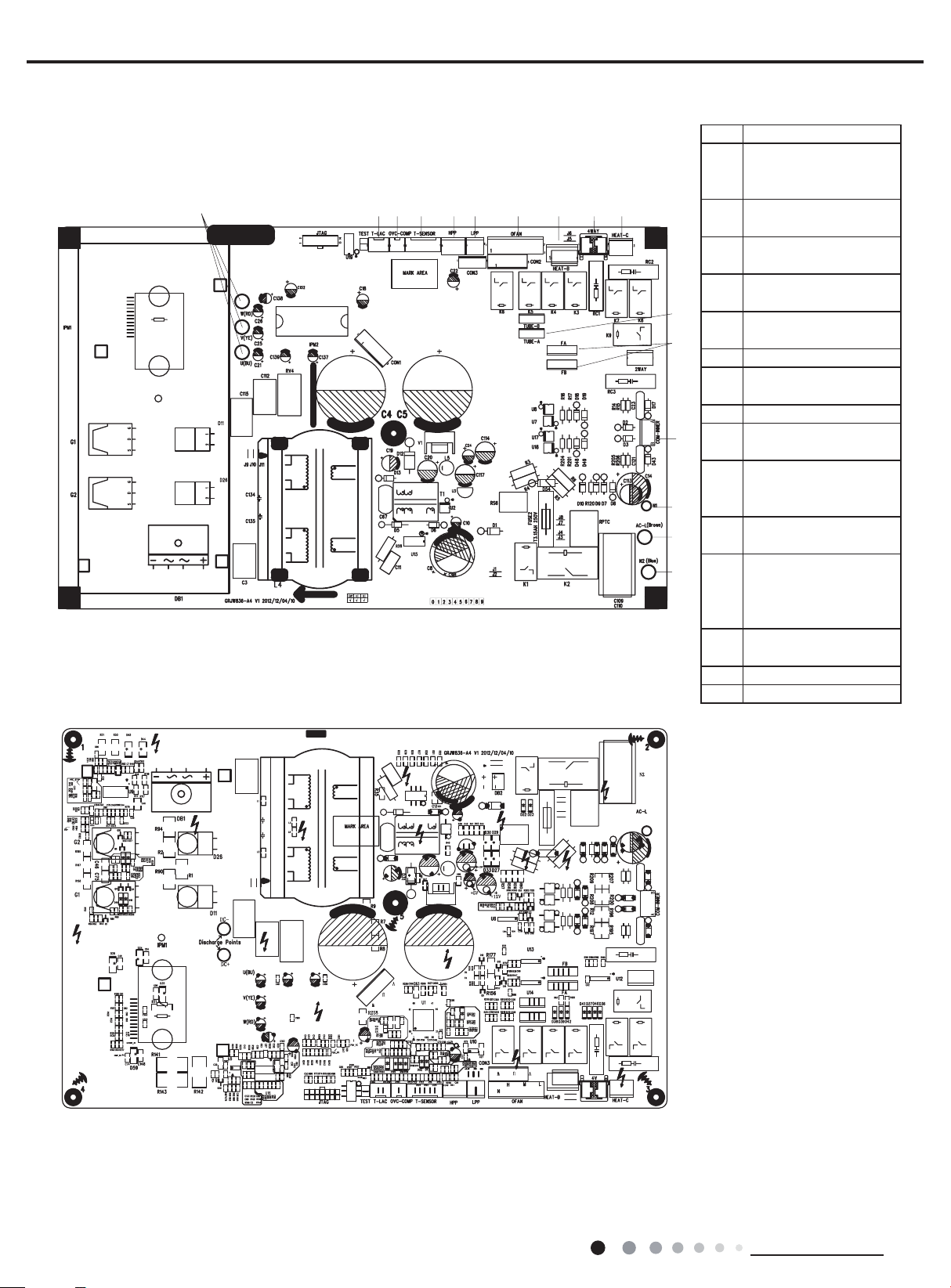
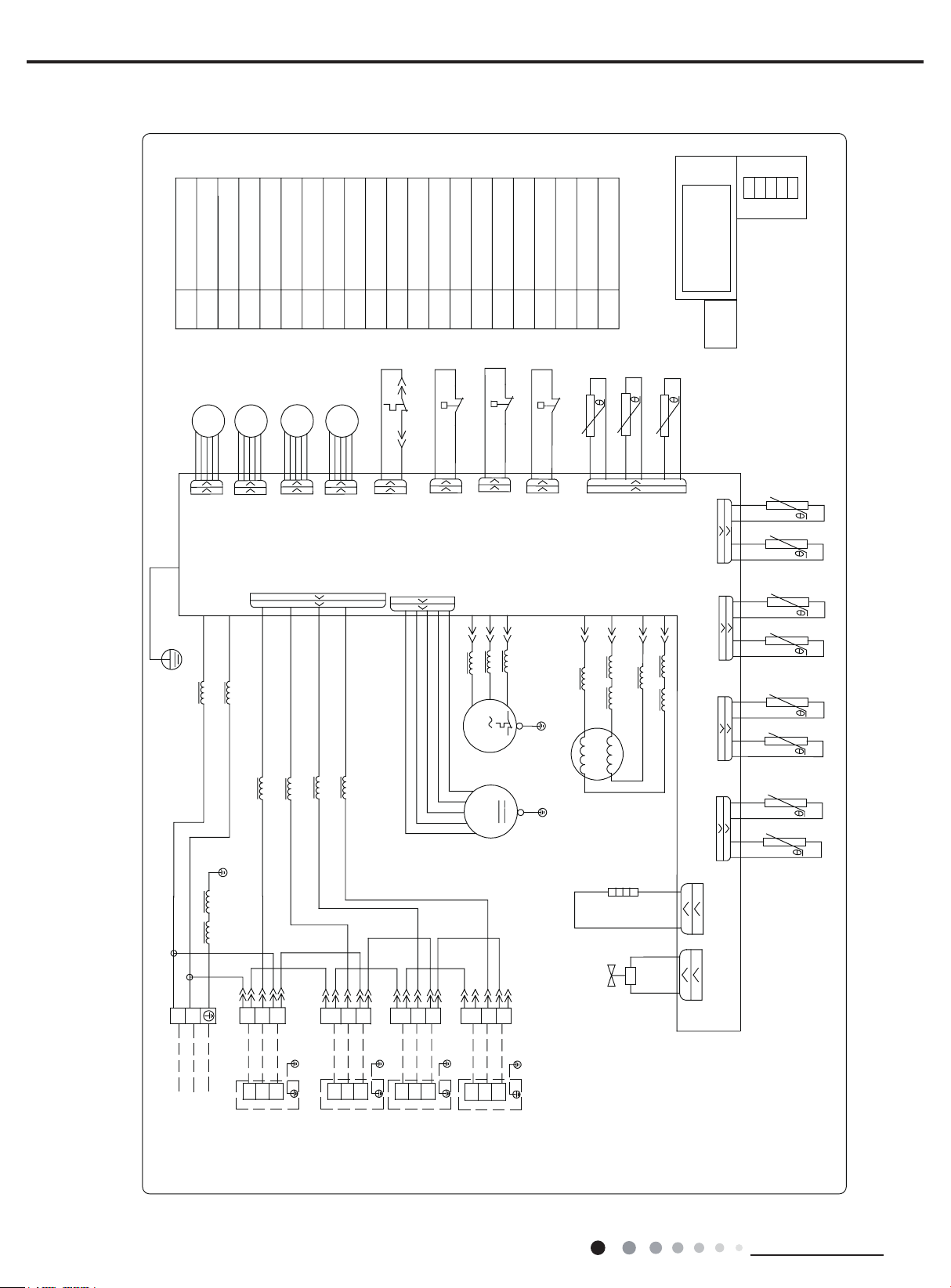
5.2 PCB Printed Diagram
Service Manual
(1)Model:GWHD(18)NK3FO
● Top view
1
● Bottom view
23 45678910
1
1 Terminal of compressor
Terminal of low-
2
temperature cooling
temperature sensor
Overload protection
3
terminal of compressor
Terminal of temperature
4
sensor for outdoor unit
High-pressure protection
5
11
12
13
14
15
16
terminal
Low-pressure protection
6
terminal
7 Terminal of outdoor fan
Electric heating terminal
8
of chassis
9 4-way valve terminal
Electric heating terminal
10
of compressor
Terminal of temperature
11
sensor wire for gas
valve and liquid valve
Terminal of electronic
12
expansion valve
Terminal of
communication wire
13
between indoor unit and
outdoor unit
Terminal of neutral wire
14
for communication
15 Terminal of live wire
16 Terminal of neutral wire
20
Technical Information
Service Manual
1234 56 879
10
12
13
14
15
16
17
18
19
20
21
1234 56 879
10
11
12
13
14
15
16
17
18
19
20
21
22
23
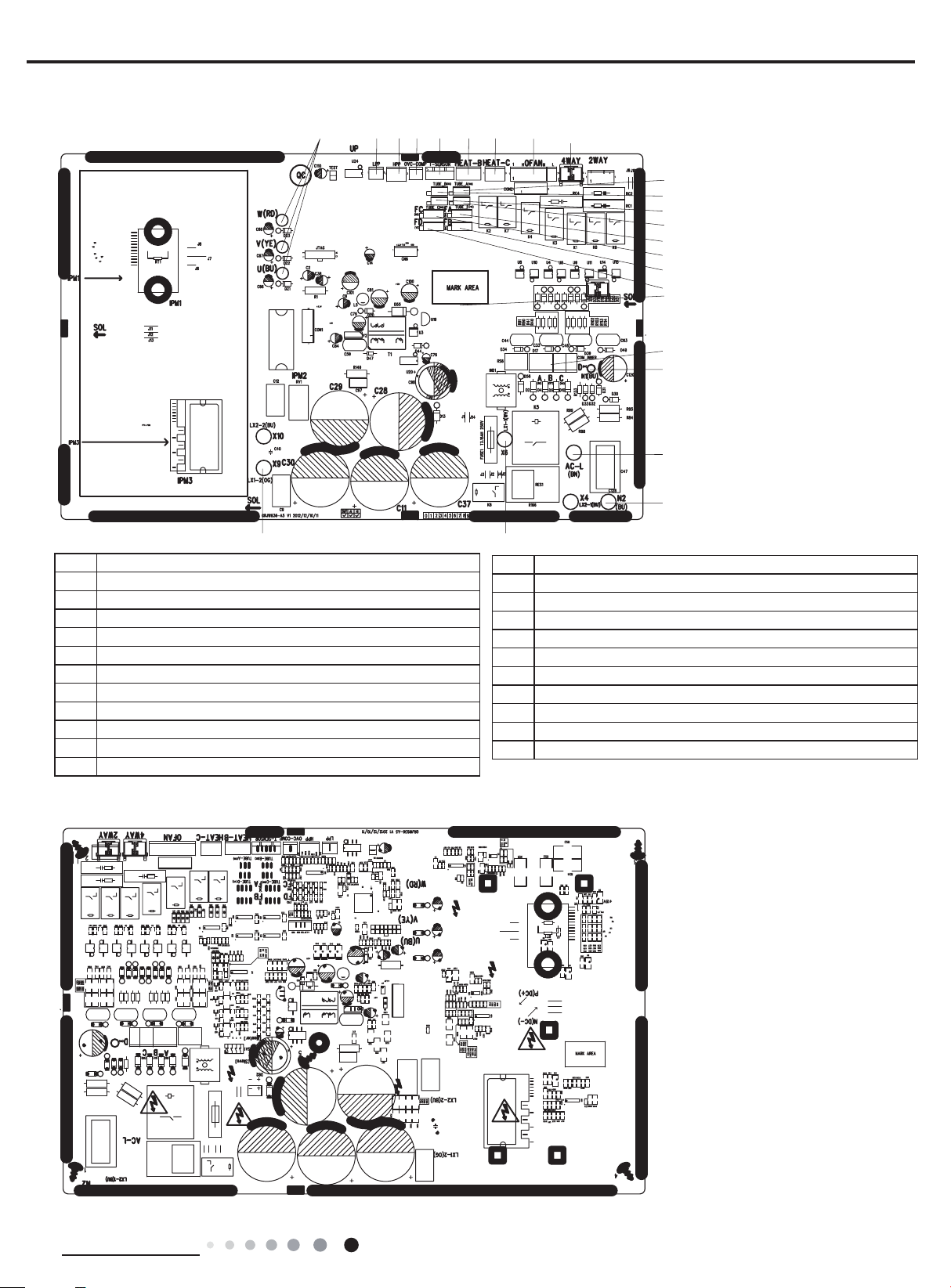
(2)Models:GWHD(24)NK3FO GWHD(24)NK3GO GWHD(28) NK3FO
● Top view
23
1 Compressor terminal
2 Low-pressure protection terminal
3 High-pressure protection terminal
4 Overload protection terminal of compressor
5 Terminal of temperature sensor of outdoor unit
6 Electric heating terminal of chassis
7 Electric heating terminal of compressor
8 Terminal of outdoor fan
9 Terminal of 4-way valve
10 Temperature sensor of liquid valve and gas valve for unit A
11 Temperature sensor of liquid valve and gas valve for unit B
12 Temperature sensor of liquid valve and gas valve for unit C
● Bottom view
11
22
13 Temperature sensor of liquid valve and gas valve for unit D
14 Electronic expansion valve for unit A
15 Electronic expansion valve for unit B
16 Electronic expansion valve for unit C
17 Electronic expansion valve for unit D
18 Communication wire with indoor unit
19 Neutral wire for communication
20 Live wire
21 Neutral wire
22 Reactor wire 1
23 Reactor wire 2
Technical Information
21
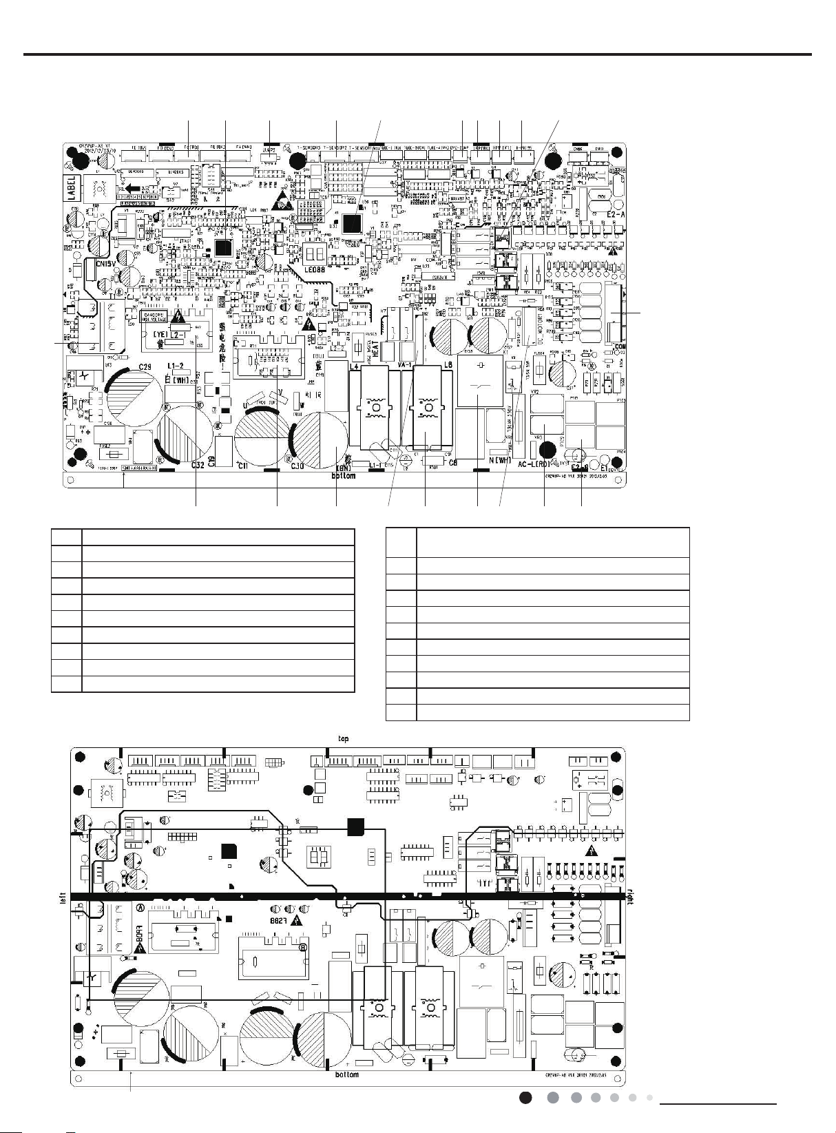
(3)Model:GWHD(36)NK3BO
● Top view
21
1 2 3 4 5 6 7 8
Service Manual
9 10
11
1 Terminal of expansion valve
2 G-MatrikII chip
3 Jumper cap
4 Terminal of temperature sensor
5 STM8S207 chip
6 Overload protection terminal of compressor
7 Low-pressure protection terminal
8 Low-pressure switch 1
9 High-pressure switch 2
10 Terminal of 4-way valve
● Bottom view
121314151617181920
11 Communication interface between indoor unit
and outdoor unit
12 PTC resistance
13 Piezoresistor
14 DC fan terminal
15 Relay
16 Common-mode induction
17 Rectier
18 Electrolytic capacitor
19 IPM module
20 PFC module
21 Transformer
22
Technical Information
Service Manual
minals of reactor's
minals of reactor's
minals of reactor's
minals of reactor's
● Top view
● Bott
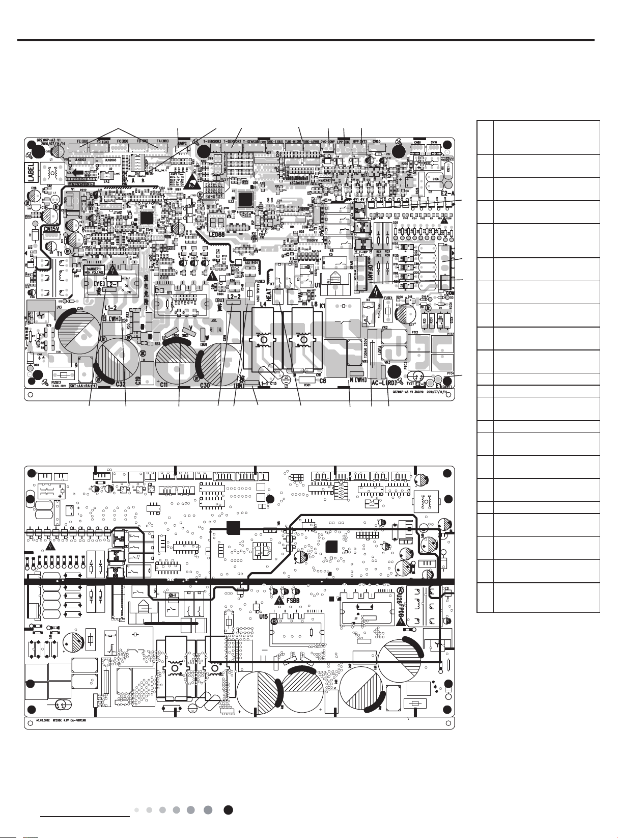
(4)Model:GWHD(42)NK3AO
om view
1234
5
67 8
FA-FE: Teminals
1
of EXV(Electronic
expansion Valve)
JUMP2:the code of
2
capcity
SA1: Master select
3
9
switch
T-SENSOR2:Teminals of
4
temperature sensor
TUBE-A - TUBE-
5
E:Teminals of tube
10
11
12
temperature sensor
OVC-COMP:Teminals of
6
overload protector
LPP:Teminals of low
7
pressure switch
HPP:Teminals of high
8
pressure switch
4V1:Teminals of 4-way
9
valve
COM:Teminals of
10
communication
11 OFAN1:Te minals of fan
12 E1:Teminals of Earth
AC-L:Teminals of line
13141516171819202122
13
wire
14 FUSE1: Fuse
N:Teminals of neureal
15
wire
HEAT:Teminals of
16
compressor band heater
L1-1:Te
17
brown wire
18 FUSE3: Fuse of fan
L2-2:Te
19
blue wire
U/V/W:Te minals of
20
compressor
L1-2:Te
21
white wire
L2-1:Te
22
yellow wire
Technical Information
23

6. Function and Control
1 Basic functions of the system
1.1 Cooling Mode
1.1.1 Cooling conditions and process:
If
operation
the
compressor start operation.
1.1.2 Stop in cooling operation
1.1.2.1 Compressor stops
The compressor stops imme
1.1.2.2 Some of the indoor units reach the stop condition (the compressor does not stop)
The
corresponding electronic expansion valve is closed to OP.
1.1.3 Cooling mode transfers to heating mode
When
are the same as stopping in cooling mode.
1.1.4 4-
1.1.5 Outdoor fan control in cooling mode
The
then
changed, the unit
When the compressor stops, the outdoor fan runs at present speed and stops after 1min.
1.2 Dry Mode
1.2.1 The dr
1.2.2 The status of 4-
1.2.3 The temperature setting range: 16 ~ 30
1.2.4 Protection function: the same as those in cooling mode;
1.2.5 In dr
The open co
1.3 Heating Mode
1.3.1 Heating conditions and process:
When one of the indoor units reaches the heating operation condition, the unit starts heating operation.
1.3.2 Stop in heating operation:
1.3.2.1 When all the indoor units reach the stop condition, the compressor stops and the outdoor fan stops after 1min;
1.3.2.2 Some of the indoor units reach the stop condition
The compressor redu
1.3.2.3 Heating mode transfers to cooling mode(dry mode), fan mode
a.
4-
For 18/24/28K
the compressor is in stop status and start the unit for cooling operation, when one of the indoor units reaches the cooling
condition, the unit start cooling operation; in this case, the electronic expansion valve, the outdoor fan and
Service Manual
compressor operates immediately according to the required frequency. For the indoor unit with no requirement, the
the unit transfers to heating mode, the 4-way valve is energized after the compressor stops for 2min. The other disposals
way valve: in this mode, the 4-way valve is closed.
outdoor fan starts before 5s of the starting of compressor. The outdoor fan will run in high speed for 3min after starting and
it will run in set speed. The fan shall run at every speed for at least 80s. (When the quantity of running indoor unit is
will enter the control described in 1.3.5.1 and 1.3.5.2);
y conditions and process are the same as those in cooling mode;
y mode, the maximum value A of the capacity requirement percentage of single unit is 90% of that in cooling mode.
ndition of the electronic expansion valve, outdoor fan and compressor is the same as those in cooling mode.
24
The compressor stops; b. the power of 4-way valve is cut off after 2min; c. the outdoor fan stops after 1min; d. the status of
way valve: energized;
diately, the outdoor fan stops after 1min.
way valve: closed;
ć;
ces the frequency immediately and operates according to the required frequency;
Technical Information

Service Manual
1.3.3 Outdoor fan control in heating mode
The outdoor fa
The fan shall run at every speed for at least 80s;
When the compressor stops, the outdoor fan stops after 1min.
1.3.4 Defrosting function
When
the
valve
compressor rises to reach the defrosting frequency.
1.3.5 Oil-returned control in heating mode
1.3.5.1 Oil-returned condition
The
1.3.5.2 Oil-returned process in heating mode
The indoor
1.3.5.3 Oil-returned finished condition in heating mode
The duration re
1.4 Fan Mode
The compressor, the outd
2. Protection Function
2.1 Mode Conflict Protection of indoor unit
When the setting mode is different of different indoor unit, the unit runs in belo
a. The mode of the first operating indoor unit is the basic mode, then compare the mode of the other indoor units to see if th
is a conflict. Cooling mode (dry mode) is in conflict
b.
the unit
2.2 Overload protection function
When
high,
compressor protection stops running.
If
compressor
compressor is longer than 7min, the protection times record will be cleared)
2.3 Discharge Protection Function
When
is a little high, the compressor frequency is
too high, the compressor protection stops running.
If
compressor
compressor is longer than 7min, the protection times record will be cleared)
n starts before 5s of the starting of compressor and then it will run in high speed for 40s;
the defrosting condition is met, the compressor stops; the electronic expansion valve of all indoor units open in big angle;
outdoor fan stops after 40s of the stop of compressor, meanwhile, the 4-way valve reverses the direction; after the 4-way
reverses the direction, the compressor starts; then begin to calculate the time of defrosting, the frequency of the
whole unit is operating in low frequency for a long time
unit displays “H1”
aches 5min
oor fan and the 4-way valve are closed; temperature setting range is 1630ć.
w status:
Fan mode is in conflict with heating mode and the heating mode is the basic mode. No matter which indoor unit operates first,
will run in heating mode.
with heating mode.
the tube temperature is a little low, the compressor raises the operation frequency; when the tube temperature is a little
the compressor frequency is restricted or lows down the operation frequency; when the tube temperature is too high, the
the discharge temperature protection continuously appears for 6 times, the compressor can’t resume running. The
can resume running after cutting off the power and then putting through the power. (if the running time of the
the discharge temperature is a little low, the compressor raises the operation frequency; when the discharge temperature
restricted or lows down the operation frequency; when the discharge temperature is
the discharge temperature protection continuously appears for 6 times, the compressor can’t resume running. The
can resume running after cutting off the power and then putting through the power. (if the running time of the
Technical Information
ere
25

2.4 Communication malfunction
Detection of the quantity
of installed indoor units:
After 3min of energizing, if the outdoor unit does not receive the communication data
ll
j
that indoor unit later, the outdoor unit
2.5 Overcurrent Protection
a. Overcurrent protection of complete unit; b. phase
2.6 Compressor high-pressure protection
2.6.1
as
e
indoor units;
2.6.2
,
the compressor can resume running only after cutting off the po
2.7 Compressor overload protection
If the compressor overload switch is detected having movement, the indoor unit
stops
the
compressor overload
an
6 times (if the running time of the compressor is longer than 30min, the protection times record
not
resume
the
po
2.8 Compressor Phase-lacking Protection
When
protection.
The
n. If the
phase-lacking
r
cutting
the
protection times record
2.9 IPM Protection
2.9.1
closed,
automatically;
longer
o
indoor unit.
d
then putting through the po
2.9.2 IPM module overheating protection
2.9.2.1 When
2.9.2.2
present
capacity
f
T
run at this frequency;
2.9.2.3
the
outdoor fan
udge that indoor unit is not installed and will treat it as it is not installed. If the outdoor unit receives the communication data of
will treat that unit as it is installed.
wire current protection; c. compressor phase current protection
When the high-pressure switch is detected cut off for 3s continuously, the compressor will enter high-pressure protection
it stops when reaching set temperature. Meanwhile, the outdoor unit will send the signal of “high-pressure protection” to th
After the appearance of high-pressure protection, when the high-pressure switch is detected closed for 6s continuously
wer and then putting through the power.
when the indoor temperature reaching set temperature. When the compressor stops for more than 3min and
switch is reset, the unit will resume operation status automatically. If the protection appears for more th
will display the corresponding malfunction as it
26
operation status automatically, but can resume running only after cutting off the power and then putting through
wer.
the compressor starts, if one of the three phases is detected open, the compressor will enter phase-lacking
malfunction will be cleared after 1min, the unit will restart and then detect if there is still has phase-lacking protectio
protection is detected for 6 times continuously, the compressor will not restart but can resume running only afte
off the power and then putting through the power. If the running time of the compressor is longer than 7min,
will be cleared.
When the IPM module protection is detected, the unit will stop as the indoor temperature reaching set temperature, PFC is
display IPM protection malfunction. After the compressor stops for 3min, the unit will resume operation status
if the IPM protection is detected for more than 6 times continuously (If the running time of the compressor is
than 7min, the protection times record will be cleared), the system will stop and send the signal of module protection t
The unit can not resume operation status automatically, but can resume running only after cutting off the power an
wer.
η85ć, prohibit to raise frequency;
T
IPM
When T
≥90ć, the operation frequency of compressor lows down by 15% every 90s according to the
IPM
requirement of the complete unit. It will keep 90s after lowing down the frequency. After lowing down the frequency, i
≥90ć, the unit will circulate the above movement until reaching the minimum frequency; if 85ćζT
IPM
When T
when T
≥95ć, the compressor stops. After the compressor stops for 3min, if T
IPM
≤85ć, the unit will run at the frequency according to the capacity requirement;
IPM
will resume operation.
Service Manual
of certain indoor unit, the outdoor unit wi
will be cleared), the unit can
ζ90ć, the unit will
IPM
ζ85ć, the compressor and
IPM
Technical Information

Service Manual
For 36K/42K
1.Function Control
1) Cooling mode
a. Turning on the unit for cooling operation, and if any one of the indoor units satisfy the cooling operation condition, the system will
start for cooling operation; and the electronic expansion valve, the outdoor fan and the compressor start operation.
b. When some of the indoor units satisfy the stop-condition while some indoor units does not satisfy the stop-condition, the
compressor does not stop, the compressor adjust the frequency according to demand. For the indoor unit with stop-condition satises,
the corresponding electronic expansion valve will be closed.
c. Change Cooling mode to heating mode
When change the unit to heating mode from cooling mode, the whole system will stop rst. Then the system will restart in heating
mode after the compressor stops.
d. 4-way valve
In this mode, the 4-way valve is closed.
e. Outdoor fan control in cooling mode
The outdoor fan starts before 5s of the starting of compressor. The outdoor fan will run in midlle speed after starting and then it will run
in set speed.
2) Dry mode (dehumidication mode)
this mode is the same as cooling mode;
3) Heating mode
a. Turning on the unit for heating operation, If any one of the indoor unit satisfy the heating condition, the system will start to run in
heating mode
b. If all the indoor units satisfy the stop-condition, the compressor stops and the outdoor fan stops after 1min;
c. If only part of the indoor units satisfy the stop-condition, the compressor decrease the frequency immediately and operates
according to demand.
d. Change Heating mode to cooling mode or dehumidication mode, the whole system will stop rst, then restart under the required
mode.
e. Defrosting function
When the defrosting condition is satised, the 4-way valve reverses the direction, the outdoor fan stop.After the 4-way valve reverses
the direction, the frequency of compressor rises, and the unit
will start defrosting under cooling cycle.
f. Oil-return control in heating mode
a)If the whole system runs in low frequency for a long time, the system will run a oil-return operation in high frequency, the indoor unit
displays “H1”, the oil-return operation will runs for 3 minutes.
4) Fan mode
Only indoor fan run. Compressor, outdoor fan and 4-way valve are closed .
2.Protection Function
1) Mode conict protection of indoor units
When the setting mode is different of different indoor unit, the unit runs in below status:
a. The system mode is determined by the rst turning on indoor unit except indoor unit is in fan mode. Cooling mode (dry mode) is in
conict with heating mode.
b. If the rst turning on unit is fan mode, and the second turning on unit is cooling or heating mode, then the system will run in cooling
or heating mode
2) Overload protection
If the tube temperature at the high pressure side is higher than normal, the compressor frequency is restricted or decreased to normal
operation frequency.
3) High exhaust temperature protection
If the exhaust temperature is higher than protection value, the compressor stops running.
If the exhaust temperature protection continuously appears for 6 times, the compressor can’t resume running. In this case, only by
cutting off the power and then reenergize that the compressor can restart. If the running duration of the compressor is longer than
7min, the protection times will be cleared to zero time.
4) Communication malfunction
Technical Information
27
Service Manual
Detection of the quantity of installed indoor units: after 3min of energizing, if the outdoor unit does not receive the communication data of
certain indoor unit, the outdoor unit will judge that indoor unit is not installed. If the outdoor unit receives the communication data of that
indoor unit later, the communication malfunction will be cleared.
5) System high-pressure protection
a. When the high-pressure switch detects the system pressure higher than limit ,then the high-pressure switch cuts off, the system will stop
to run.
b.If high-pressure protection is detected for two times within one hour, only by cutting off the power and then reenergize that the compressor
can restart.
6)System low-pressure protection
a. When the low-pressure switch detects the system pressure lower than limit ,then the los-pressure switch cuts off , the system will stop to
run.
b. If low-pressure protection is detected for two times within one hour, only by cutting off the power and then reenergize that the compressor
can restart.
7) Compressor overload protection
No matter the compressor is on or off, when the compressor overload switch is detected activated, the system will stop and indoor unit
will display H3. If the compressor overload protection appears for more than 6 times, in this case, only by cutting off the power and then
reenergize that the compressor can restart. If the running duration of the compressor is longer than 30min, the protection times will be
cleared to zero.
3.Other function
1) Refrigerant Recovery
When the unit is powered on and runs under the COOL mode, it is available within ve minute to go the refrigerant recovery mode by
pressing three times the “LIGHT” button on the wireless controller in three seconds with “Fo”displayed.
How to quit the refrigerant recovery:
When the refrigerant recovery has started, it will quit when there is a signal from the wireless controller or it has run for ten minutes.
2) Setting function of master/slave indoor unit
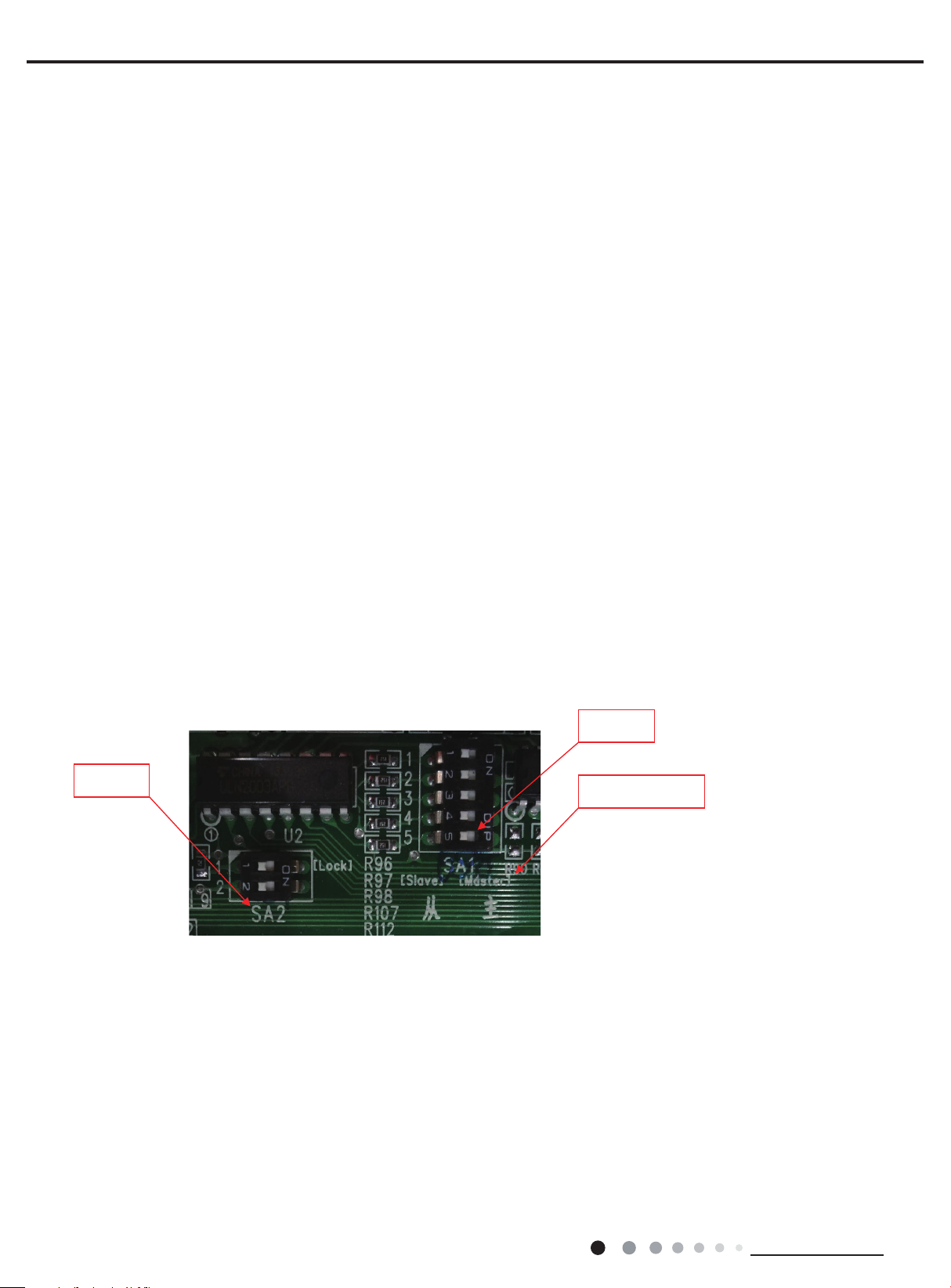
Picture of DIP switch on outdoor mainboard :
SA1(5-bit): dial-switch for master/slave indoor unit,
SA2(2-bit): dial-switch for mode locking (not for wall mounted indoor units)
SA1
SA2
5-bit dial-switch to set master/slave indoor unit: it is corresponding to indoor units of no.1 to no.5. Dial the switch to ON(master side. Right
side) to set that indoor unit as master indoor unit , and dial the switch to slave side(left side) to set indoor unit as slave indoor unit. There
can be only one master unit in a system, If more than one indoor units are set as master unit, the unit with biggest number is the master
unit. (biggest number here means number 1 to number 5 on the switch)
2-bit dial-switch to set mode locking
(note:
1.only use no.1 bit. no.2 bit is for future use
2.this function is only for duct and cassette unit, not for wall mounted unit:
Locked mode: Switch no.1 bit to “ON”side(lock side, or right side on the picture): even the master indoor unit is off, the system will run
according to the mode before the master unit off.
Unlocked mode: Switch no.1 bit to left side on the picture: If the master indoor unit is off , the system will not care what the master unit
mode was, it will run according to the mode of the rst turning on slave indoor unit.
Note: For wall-mounted indoor unit, unlocked model is default, and locked mode is invalid.
master/slave
28
Technical Information
 Loading...