

Gree GWHD(18)ND3CO, GWHD(24)ND3CO, GWHD(30)ND3CO, GWHD(36)ND3AO, GWHD(42)ND3AO Installation Manual
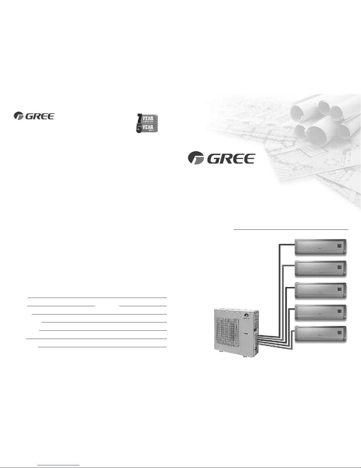
MULTI
DUCTLESS INVERTER
HEAT PUMP
INSTALLATION MANUAL
Models:
GWHD(18)ND3CO
GWHD(24)ND3CO
GWHD(30)ND3CO
GWHD(36)ND3AO
GWHD(42)ND3AO
GREE ELECTRIC APPLIANCES, INC.
www.greecomfort.com
LIMITED WARRANTY
GREE distributor (hereinafter “Company”) warrants this product against failure due to defect in materials or workmanship under normal use and maintenance as
f
ollows. All warranty periods begin on the date of original installation. If the date cannot be verified, the warranty period begins one hundred twenty (120) days from
date of manufacture. If a part fails due to defect during the applicable warranty period Company will provide a new or remanufactured part, at Company’s option,
to replace the failed defective part at no charge for the part. This limited warranty is subject to all provisions, conditions, limitations and exclusions listed below.
• Seven (7) years on compressor and Five (5) years on all parts to the original registered end‐user.
• One (1) year warranty on remote controller unit.
• Proper installation – Limited warranty applies only to systems that are installed by a state certified or licensed HVAC contractor, under applicable local and
state law in accordance with all applicable building codes and permits; GREE installation and operation instructions and good trade practices.
• Warranty applies only to products remaining in their original installation location.
• Defective parts must be returned to the distributor through a registered servicing dealer for credit.
LIMITATIONS OF WARRANTIES: ALL IMPLIED WARRANTIES AND/OR CONDITIONS (INCLUDING IMPLIED WARRANTIES OR CONDITIONS OF MERCHANTABILITY
AND FITNESS FOR A PARTICULAR USE OR PURPOSE) ARE LIMITED TO THE DURATION OF THIS LIMITED WARRANTY, SOME STATES OR PROVINCES DO NOT ALLOW
LIMITATIONS ON HOW LONG AN IMPLIED WARRANTY OR CONDITION LASTS, SO THE ABOVE MAY NOT APPLY TO YOU. THE EXPRESS WARRANTIES MADE IN THIS
WARRANTY ARE EXCLUSIVE AND MAY NOT BE ALTERED, ENLARGED, OR CHANGED BY ANY DISTRIBUTOR, DEALER, OR OTHER PERSON, WHATSOEVER.
THIS WARRANTY DOES NOT COVER:
1. Labor or other costs incurred for diagnosing, repairing, removing, installing, shipping, servicing or handling of either defective parts, or replacement parts,
or new units.
2. Normal maintenance as outlined in the installation and servicing instructions or Owner’s Manual, including filter cleaning and/or replacement and lubrication.
3. Failure, damage or repairs due to faulty installation, misapplication, abuse, improper servicing, unauthorized alteration or improper operation.
4. Failure to start due to voltage conditions, blown fuses, open circuit breakers, or damages due to the inadequacy or interruption of electrical service.
5. Failure or damage due to floods, winds, fires, lightning, accidents, corrosive environments (rust, etc.) or other conditions beyond the control of the Company.
6. Parts not supplied or designated by Company, or damages resulting from their use.
7. Products installed outside USA and Canada.
8. Electricity or fuel costs, or increases in electricity or fuel costs from any reason whatsoever, including additional or unusual use of supplemental electric heat.
9. Any cost to replace, refill or dispose of refrigerant, including the cost of refrigerant.
10. Any special, indirect or consequential property or commercial damage of any nature whatsoever. Some states or provinces do not allow the exclusion of
incidental or consequential damages, so the above limitation may not apply to you.
For additional warranty exclusions, visit www.GreeComfort.com
.
This warranty gives you specific legal rights, and you may also have other rights which vary from state to state or province to province.
For warranty service or repair, contact your installing contractor. You may find the installer’s name on the equipment or in your Owner’s packet.
Complete product registration below and send back by e‐mail at
service@twclimate.com
PRODUCT REGISTRATION
Model No.
Serial No. Date of Installation
Owner Name
Address of Installation
Installing Contractor
Address
Phone No. / E-mail
WSO021513-DLSWARR-HP-Rev 3-8-13
Gree Electric Appliances, Inc ©2014 Cat No: DFS-MULTI-HP-1IN
1 2
SAFETY PRECAUTIONS
Please read the following before installation.
Recognize safety information. This is the safety-alert symbol. When you see this
symbol on the unit and in instructions or manuals, be alert to the potential for personal
injury. Understand these signal words: DANGER, WARNING, and CAUTION. These
words are used with the safety-alert symbol.
DANGER identifies the most serious hazards which will result in severe personal injury
or death.
WARNING signifies hazards which could result in personal injury or death.
CAUTION is used to identify unsafe practices which may result in minor personal
injury or product and property damage.
NOTE is used to highlight suggestions which will result in enhanced installation,
reliability, or operation.
Thank you for choosing a
Gree Multi Ductless Heat Pump
for your customer.
Please read this installation manual carefully before installing and
starting up the Multi System. Take a moment to fill out the product
and installation form on the back cover. Retain both the manual
and installation record for future reference.
NOTE: Your actual heat pump system and related devices may differ from the images
shown in this manual.
This appliance is not intended for use by children without responsible adult supervision.
Proper care should be taken to ensure safety.
Heat pumps, air conditioners & heating equipment should be installed, started up, and
serviced only by qualified installers and service technicians. Air conditioning, heat pumps
and refrigeration systems are hazardous due to high voltage electrical components, high
refrigerant pressures, and moving parts.
WARNING
Contents
• Safety Precautions 2
• System Requirements 4
• Suggested Tools 5
• Site Instructions 6
• Dimensions 7
• Indoor Unit 9
• Outdoor Unit 12
• Refrigerant Piping 13
• Power and Wiring 16
• Vacuum Testing 19
• Start-up 21
• Troubleshooting 22
4
SAFETY PRECAUTIONS
• The unit should be installed and serviced only by trained, qualified installers and service
mechanics. Untrained personnel can perform basic maintenance functions such as
cleaning coils. All other operations should be performed by trained service personnel.
• Owner should be cautioned that children should not play with the appliance.
ELECTRICAL SHOCK HAZARD
Failure to follow this warning could result in personal injury or death.
• Before installing, servicing or modifying the system, the main electrical disconnect switch
must be in the OFF position. There may be more than one disconnect switch. Lock out
and tag all switches with a warning label.
General Safety Precautions
• A dedicated power supply circuit should be used in accordance with local electrical
safety regulations and National Electrical Codes (NEC).
• Ensure that the entire system is reliably grounded.
• Use proper size circuit breaker to protect equipment against short circuit and
overload conditions.
• The system must be positioned at least 5 feet from combustive surfaces.
• Observe all local codes and regulations.
INSTALLATION SITE INSTRUCTIONS
Proper installation site is vital for correct and reliable operation of the system.
Avoid the following installation locations :
• Strong heat sources, vapors, flammable gas or volatile liquids.
• High-frequency electro-magnetic waves, generated by radio equipment, welders
or medical equipment.
3
WARNING
CAUTION
SYSTEM REQUIREMENTS
Piping Requirements
REFRIGERANT CHARGE
ELECTRICAL REQUIREMENTS
OUTDOOR UNITS in (mm)
Notes: 1) System must be on a single dedicated circuit.
2) Main power is supplied to the outdoor unit.
3) Use table above to size over current protection.
4) Follow all local building codes and NEC (National Electrical Code) regulations.
Interconnecting Cable: Recommended cable - 14/4 AWG stranded bare copper conductors THHN 600V unshielded wire
Note: Use shield cable if installation is in close proximity of RF and EMI transmitting devices.
Condensate Drain Size: 5/8-in OD 7/16-in ID
Note: Insulate condensate drain hose to prevent sweating and possible water damage.
U
nit Size (BtuH)
Liquid Line
in(mm)
Suction/Gas Line
in(mm)
1
8,000
Port 1 1/4 (6) 3/8 (9.5)
Port 2 1/4 (6) 3/8 (9.5)
P
ort 1 1/4 (6) 3/8 (9.5)
2
4,000 Port 2 1/4 (6) 3/8 (9.5)
Port 3 1/4 (6) 3/8 (9.5)
Port 1 1/4 (6) 3/8 (9.5)
30,000
Port 2 1/4 (6) 3/8 (9.5)
Port 3 1/4 (6) 3/8 (9.5)
Port 4 1/4 (6) 3/8 (9.5)
Port 1 1/4 (6) 3/8 (9.5)
36,000
Port 2 1/4 (6) 3/8 (9.5)
Port 3 1/4 (6) 1/2 (12)
Port 4 3/8 (9.5) 5/8 (16)
Port 1 1/4 (6) 3/8 (9.5)
Port 2 1/4 (6) 3/8 (9.5)
42,000 Port 3 1/4 (6) 1/2 (12)
Port 4 1/4 (6) 1/2 (12)
Port 5 3/8 (9.5) 5/8 (16)
Unit Size
Min Pipe
Max Total Pipe Max Equivalent Max Elev btwn Max Elev btwn
(BtuH) Length ft(m) Length ft(m) Pipe Length ft(m) IND Units ft
IND& OTDUnits ft(m)
18,000 10 (3) 66 (20) 33 (10) 16 33 (10)
24,000 10 (3) 230 (70) 66 (20) 33 66 (20)
30,000 10 (3) 230 (70) 66 (20) 33 66 (20)
36,000 10 (3) 230 (70) 82 (25) 50 82 (25)
42,000 10 (3) 262 (80) 82 (25) 50 82 (25)
Unit Size
Voltage
Min Circuit Max Overcurrent Main Power
(BtuH) Amps (MCA) Protection (MOP) Wire Size (AWG)**
18,000 208/230v - 1ph 60hz 13 20 12
24,000 208/230v - 1ph 60hz 20 30 10
30,000 208/230v - 1ph 60hz 26 45 8
36,000 208/230v - 1ph 60hz 28 45 8
42,000 208/230v - 1ph 60hz 29 50 6
INDOOR UNITS in (mm)
Unit Size (BtuH)
Liquid Line
in(mm)
Suction/Gas Line
in(mm)
9,000 1/4 (6) 3/8 (9.5)
12,000 1/4 (6) 3/8 (9.5)
18,000 1/4 (6) 1/2 (12)
**Main power wire from electrical panel to outdoor unit.
*Precharge amount for up to 25-ft of refrigerant pipe.
REFRIGERANT PIPE LENGTHS
Unit Size Refrigerant Factory System Additional
(BtuH) Type Charge oz (kg)* Charge oz/ft (g/m)
18,000 R410A 48 (1.4) 0.2 (20)
24,000 R410A 78 (2.2) 0.2 (20)
30,000 R410A 78 (2.2) 0.2 (20)
36,000 R410A 102 (2.9) 0.2 (22)
42,000 R410A 169 (4.8) 0.2 (22)
6
INSTALLATION SITE INSTRUCTIONS
Step 1
Installation Site of Indoor Unit
Select a site that allows for the following:
• Ensure the installation complies with the installation minimum dimensions and meets the
minimum and maximum connecting piping length and maximum change in elevation.
•
Air inlet and outlet will be clear of obstructions, ensuring proper airflow throughout the room.
• Condensate can be easily and safely drained.
• All connections can be easily made to outdoor unit.
• Indoor unit is out of reach of children.
• A wall strong enough to withstand the full weight and vibration of the unit.
• Filter can be easily accessed for cleaning.
• Leave enough free space to allow access for routine maintenance.
• Install at least 10 ft. (3 m) away from the antenna of TV set or radio. Operation of the air
conditioner may interfere with radio or TV reception in areas where reception is weak.
An amplifier may be required for the affected device.
• Do not install in a laundry room or by a swimming pool.
• Determine if condensate pumps are required to properly drain condensate water from
the indoor units.
Installation Site of Outdoor Unit
Select a site that allows for the following:
• Outdoor location meets all minimum installation distances defined in the Installation
Dimensions section.
• Sound from outdoor unit will not annoy neighbors.
• All connections can be easily made to indoor unit.
• Air inlet and outlet will be clear of obstructions to ensure proper airflow.
• Wall or roof is strong enough to withstand the full weight and vibration of the outdoor
unit (for wall or roof installation only).
• Outdoor unit is out of reach of children and does not obstruct walkways.
• Outdoor unit is not exposed to direct sunlight or strong wind.
• Maintenance and repairs can be easily performed on the outdoor unit.
• Ensure the installation complies with the minimum and maximum connecting piping
length and maximum change in elevation criteria.
5
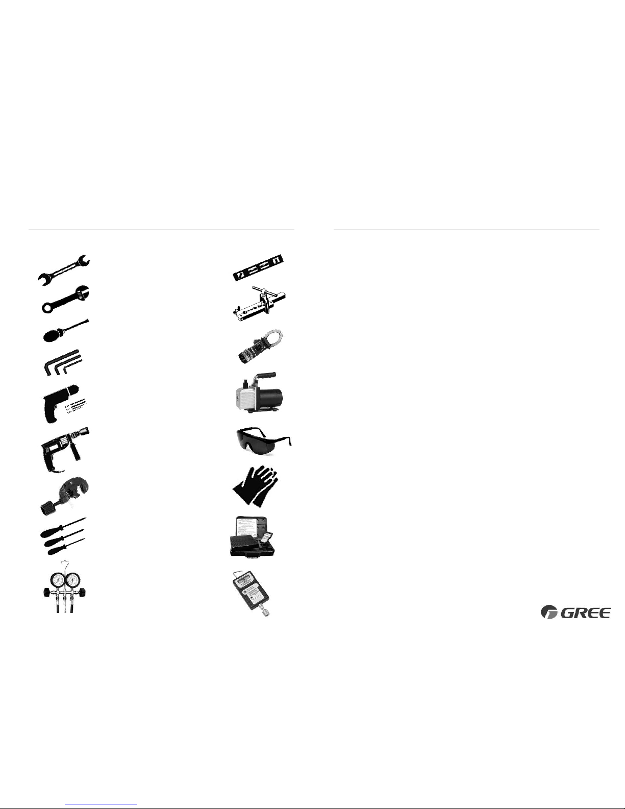
• Standard Wrench
• Adjustable/Crescent Wrench
• Torque Wrench
• Hex Keys or Allen Wrenches
• Drill & Drill Bits
• Hole Saw
• Pipe Cutter
• Screw drivers (Phillips & Flat blade)
• Manifold and Gauges
• Level
• R410A Flaring Tool
• Clamp on Amp Meter
• Vacuum Pump
• Safety Glasses
• Work Gloves
• Refrigerant Scale
• Micron Gauge
SUGGESTED TOOLS
7
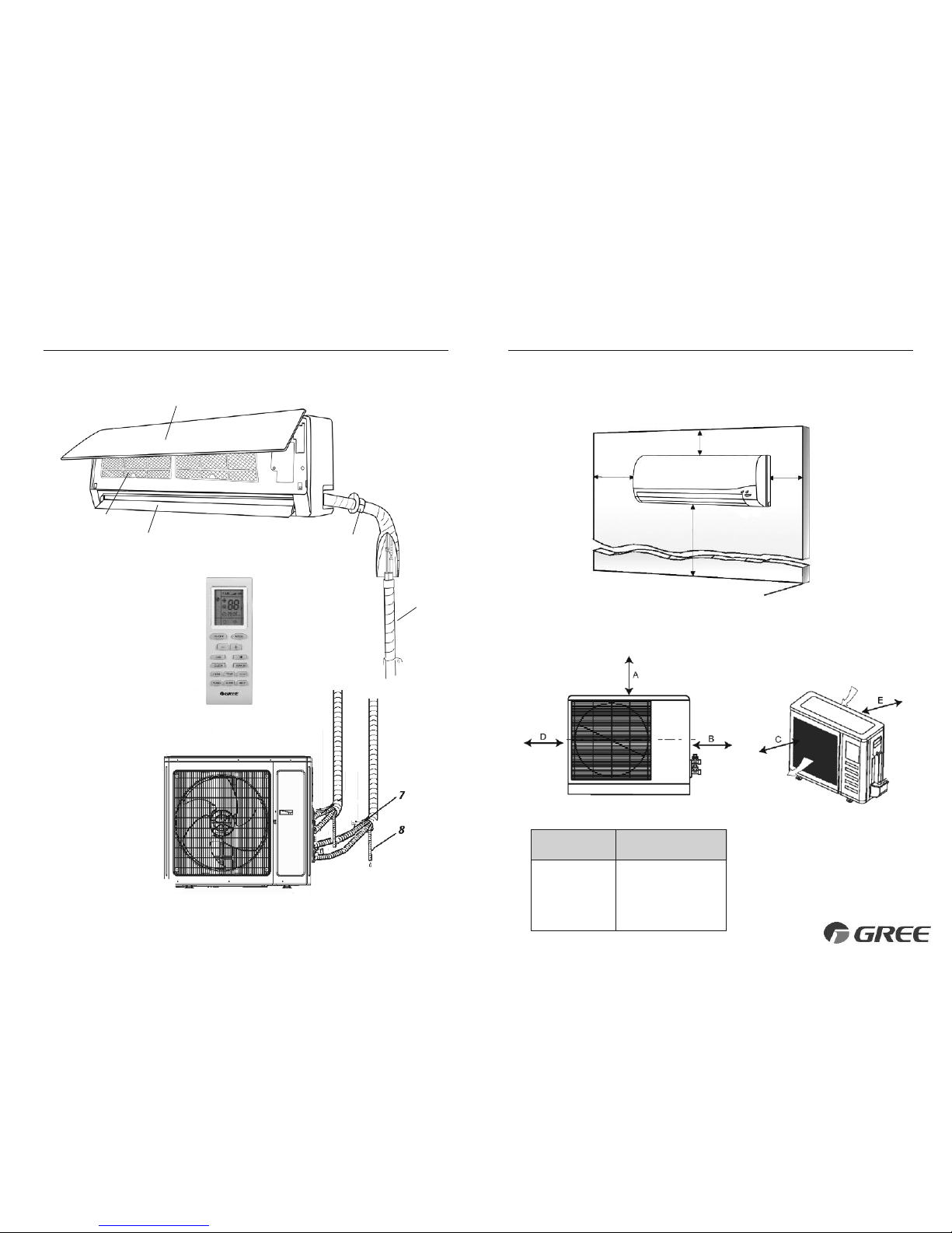
INSTALLATION DIMENSIONS
Indoor unit
Part Name
1. Remote Controller
2. Front Panel
3. Air Filter
4. Horizontal Louver
5. Wall Hole Sleeve
6. Insulation
7. Refrigerant Pipes
8. Drain Hose
Outdoor unit
2
3
6
5
8
7
4
1
8
INSTALLATION DIMENSIONS
Minimum indoor clearances
Minimum outdoor clearances
Outdoor Unit
Minimum Distances
in (mm)
A 20 (500)
B 20 (500)
C 24 (610)
D 12 (305)
E 12 (305)
5 in
(0.13m)
5 in
(0.13m)
6 ft (1.8m)
6 in (0.15m)
Air inlet
Air outlet
Ceiling
Floor
 Loading...