

Gree GWH12ACC-K6DNA5D, GWH18ACD-K6DNA4D, GWH09ACC-K6DNA1A, GWH18ACD-K6DNA5D, GWH12ACC-K6DNA4D Service Manual
...
Service Manual
Models:
Change for life
GREE ELECTRIC APPLIANCES, INC. OF ZHUHAI
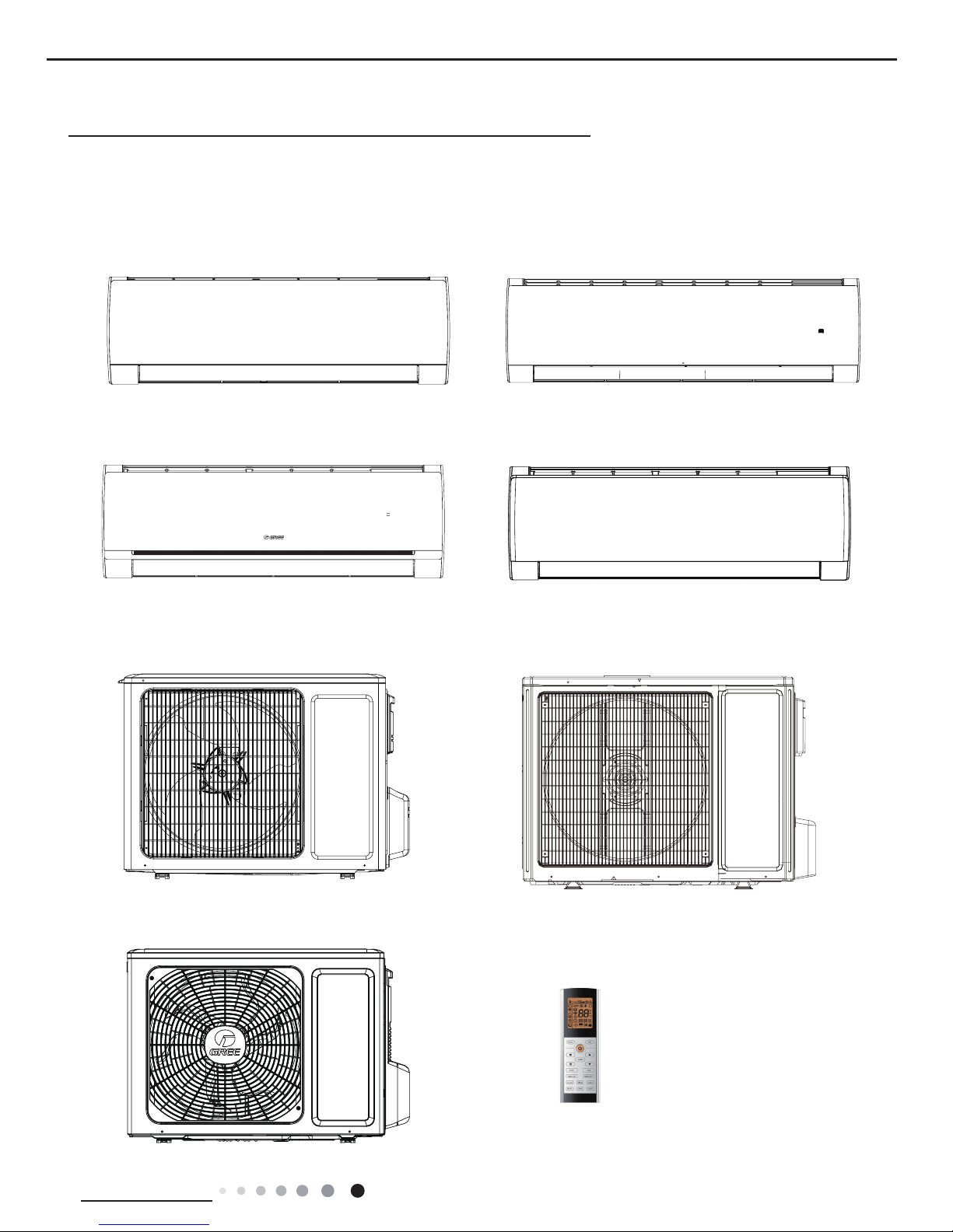
GWH09ACC-K6DNA1A
GWH12ACC-K6DNA1D
GWH12ACC-K6DNA4D
GWH12ACC-K6DNA5D
GWH18ACD-K6DNA1D
GWH18ACD-K6DNA5D
GWH18ACD-K6DNA4D
GWH24ACE-K6DNA1A
(Refrigerant R32)
Models:

Service Manual
Table of Contents
Part
Ⅰ
: Technical Information
.......................................................................1
1. Summary
......................................................................................................................1
2. Specications
..........................................................................................................3
2.1 Specication Sheet ...........................................................................................................3
2.2 Operation Characteristic Curve ...................................................................................... 11
2.3 Capacity Variation Ratio According to Temperature ....................................................... 11
2.4 Cooling and Heating Data Sheet in Rated Frequency ...................................................12
2.5 Noise Curve ....................................................................................................................12
3. Outline Dimension Diagram
......................................................................13
3.1 Indoor Unit ......................................................................................................................13
3.2 Outdoor Unit ...................................................................................................................14
4. Refrigerant System Diagram
....................................................................16
5. Electrical Part
.........................................................................................................17
5.1 Wiring Diagram ...............................................................................................................17
5.2 PCB Printed Diagram .....................................................................................................22
6. Function and Control
......................................................................................26
6.1 Remote Controller Introduction .....................................................................................26
6.2 GREE+ App Operation Manual ......................................................................................32
6.3 Ewpe Smart App Operation Manual ...............................................................................33
6.4 Brief Description of Modes and Functions ......................................................................34
Part
Ⅱ
: Installation and Maintenance
.................................................45
7. Notes for Installation and Maintenance
..........................................45
8. Installation
................................................................................................................49
8.1 Installation Dimension Diagram ......................................................................................49
8.2 Installation Parts-checking ............................................................................................51
8.3 Selection of Installation Location ....................................................................................51
8.4 Requirements for electric connection .............................................................................51
8.5 Installation of Indoor Unit ................................................................................................52
8.6 Installation of Outdoor Unit .............................................................................................54
8.7 Vacuum Pumping and Leak Detection ...........................................................................55
8.8 Check after Installation and Test Operation ...................................................................55
Table of Contents

Service Manual
9. Maintenance
............................................................................................................56
9.1 Error Code List ...............................................................................................................56
9.2 Procedure of Troubleshooting ........................................................................................64
9.3 Troubleshooting for Normal Malfunction .........................................................................77
10. Exploded View and Parts List
..............................................................79
10.1 Indoor Unit ....................................................................................................................79
10.2 Outdoor Unit .................................................................................................................86
11. Removal Procedure
.......................................................................................93
11.1 Removal Procedure of Indoor Unit ...............................................................................93
11.2 Removal Procedure of Outdoor Unit ............................................................................98
Appendix:
......................................................................................................................113
Appendix 1: Reference Sheet of Celsius and Fahrenheit ..................................................113
Appendix 2: Conguration of Connection Pipe ...................................................................113
Appendix 3: Pipe Expanding Method .................................................................................114
Appendix 4: List of Resistance for Temperature Sensor .................................................... 115
Table of Contents
1
Technical Information
Service Manual
1. Summary
Part
Ⅰ
: Technical Information
Indoor Unit
GWH09ACC-K6DNA1A/I
GWH12ACC-K6DNA1D/I
GWH18ACD-K6DNA1D/I
Outdoor Unit
GWH12QC-K6DNA1D/O
GWH09ACC-K6DNA1A/O
Remote Controller
YAC1FB9(WiFi)
GWH18QD-K6DNA1D/O
GWH24QE-K6DNA1E/O
GWH24ACE-K6DNA1A/I
GWH12ACC-K6DNA4D/I
GWH18ACD-K6DNA4D/I
GWH24ACE-K6DNA4A/I
GWH12ACC-K6DNA5D/I
GWH18ACD-K6DNA5D/I
2
Technical Information
Service Manual
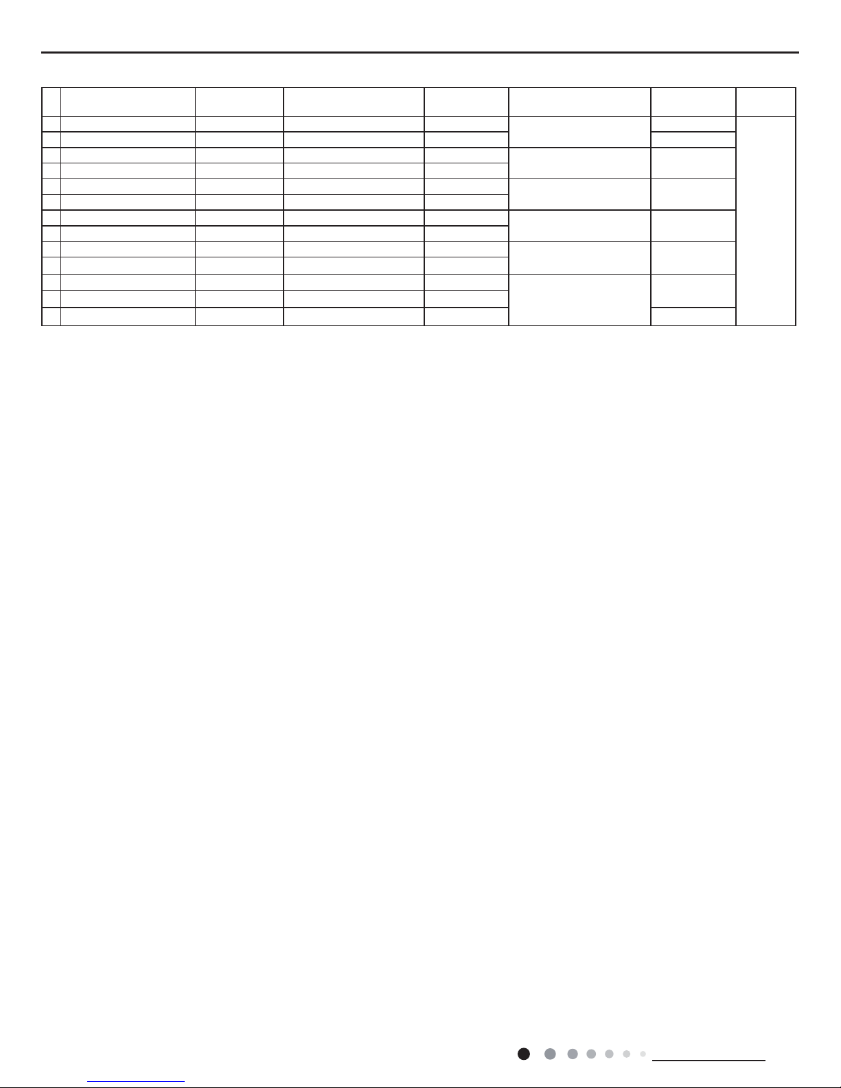
Model List:
No Model Product code Indoor model
Indoor
product code
Outdoor model
Outdoor
product code
Remote
Controller
1 GWH09ACC-K6DNA1A CB497003000 GWH09ACC-K6DNA1A/I CB497N03000
GWH09ACC-K6DNA1A/O
CB497W03000
YAC1FB9
(WiFi)
2 GWH09ACC-K6DNA1A CB497003001 GWH09ACC-K6DNA1A/I CB497N03000 CB497W03001
3 GWH12ACC-K6DNA1D CB497001601 GWH12ACC-K6DNA1D/I CB497N01600
GWH12QC-K6DNA1D/O CB419W15501
4 GWH12ACC-K6DNA4D CB344000701 GWH12ACC-K6DNA4D/I CB344N00700
5 GWH12ACC-K6DNA5D CB341000600 GWH12ACC-K6DNA5D/I CB341N00600
GWH12QC-K6DNA1D/O CB419W15500
6 GWH12ACC-K6DNA1D CB497001600 GWH12ACC-K6DNA1D/I CB497N01600
7 GWH18ACD-K6DNA1D CB497002100 GWH18ACD-K6DNA1D/I CB497N02100
GWH18QD-K6DNA1D/O CB419W15600
8 GWH18ACD-K6DNA5D CB341000700 GWH18ACD-K6DNA5D/I CB341N00700
9 GWH18ACD-K6DNA4D CB344000901 GWH18ACD-K6DNA4D/I CB344N00900
GWH18QD-K6DNA1D/O CB419W15601
10 GWH18ACD-K6DNA1D CB497002101 GWH18ACD-K6DNA1D/I CB497N02100
11 GWH24ACE-K6DNA1A CB497001901 GWH24ACE-K6DNA1A/I CB497N01900
GWH24QE-K6DNA1E/O
CB419W15701
12 GWH24ACE-K6DNA4A CB344000801 GWH24ACE-K6DNA4A/I CB344N00800
13 GWH24ACE-K6DNA1A CB497001900 GWH24ACE-K6DNA1A/I CB497N01900 CB419W15700
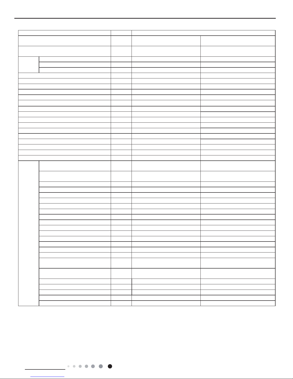
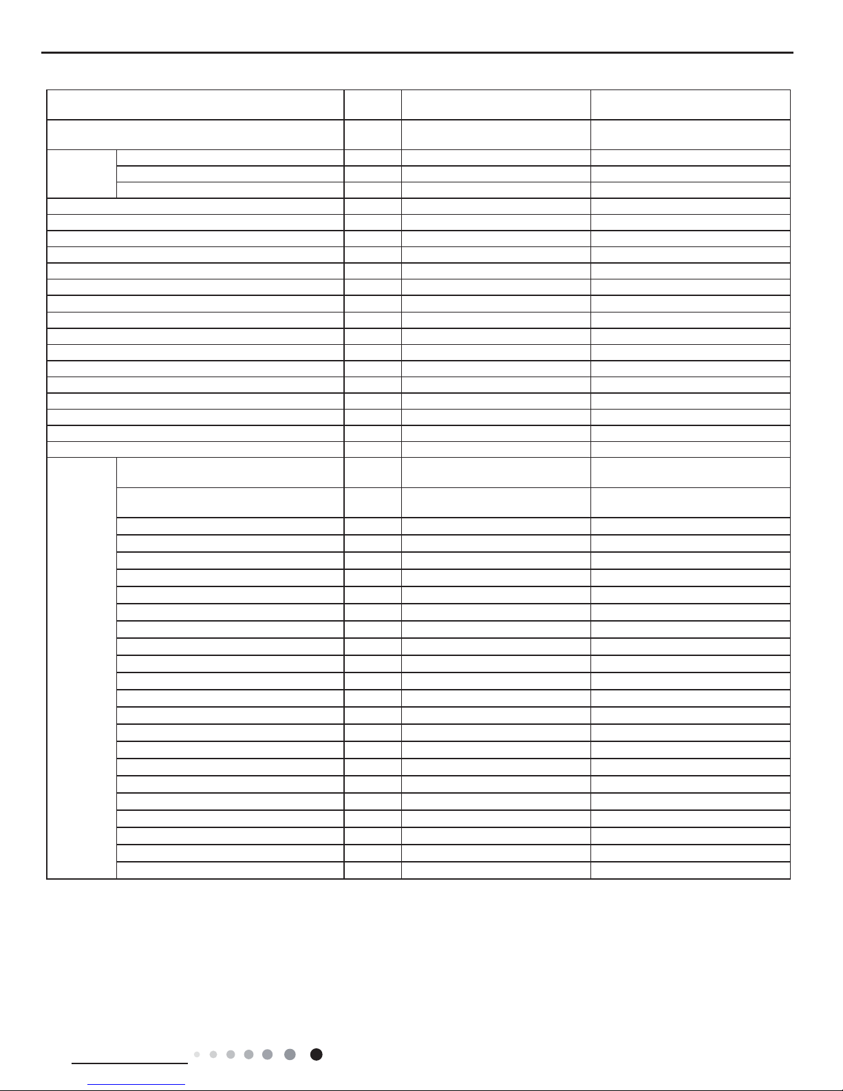
3
Technical Information
Service Manual
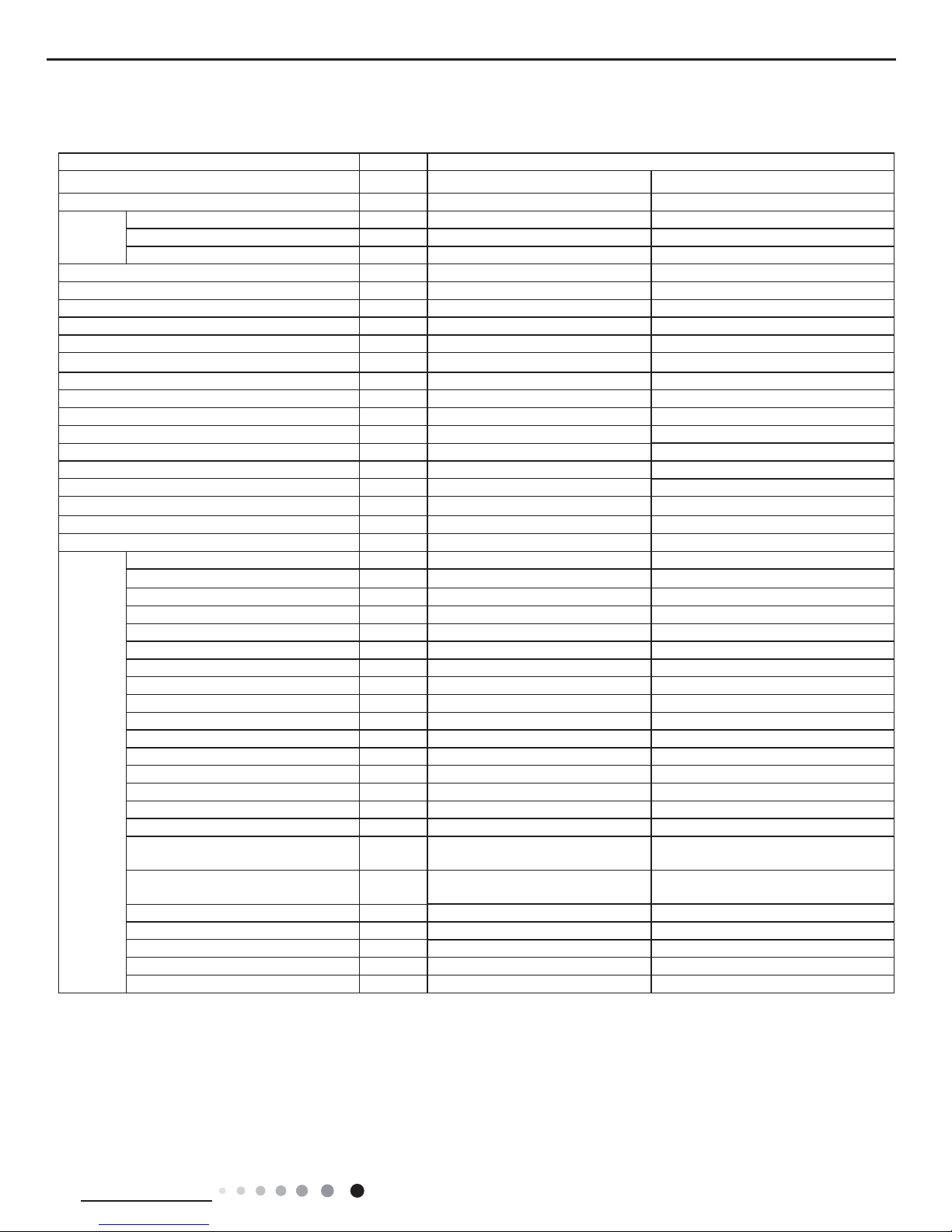
2. Specications
2.1 Specication Sheet
Parameter Unit Value
Model GWH09ACC-K6DNA1A GWH09ACC-K6DNA1A
Product Code CB497003000 CB497003001
Power
Supply
Rated Voltage V~ 220-240 220-240
Rated Frequency Hz 50 50
Phases 1 1
Power Supply Mode Outdoor Outdoor
Cooling Capacity W 2700 2700
Heating Capacity W 3000 3000
Cooling Power Input W 805 805
Heating Power Input W 779 779
Cooling Current Input A 3.8 3.8
Heating Current Input A 3.5 3.5
Rated Input W 1500 1500
Rated Current A 3.8 3.8
Air Flow Volume(SS/H/MH/M/ML/L/SL) m
3
/h 610/570/540/470/440/420/390 610/570/540/470/440/420/390
Dehumidifying Volume L/h 0.8 0.8
EER W/W 3.35 3.35
COP W/W 3.85 3.85
SEER W/W 6.8 6.8
SCOP(Average/Warmer/Colder) W/W 4.1/5.1/3.3 4.1/5.1/3.3
Application Area m
2
12-18 12-18
Indoor
Unit
Indoor Unit Model GWH09ACC-K6DNA1A/I GWH09ACC-K6DNA1A/I
Indoor Unit Product Code CB497N03000 CB497N03000
Fan Type Cross-ow Cross-ow
Fan Diameter Length(DXL) mm Φ98X633.5 Φ98X633.5
Cooling Speed(SS/H/MH/M/ML/L/SL) r/min 1200/1100/1050/950/900/850/800 1200/1100/1050/950/900/850/800
Heating Speed(SS/H/MH/M/ML/L/SL) r/min 1150/1100/1050/1000/950/900/850 1150/1100/1050/1000/950/900/850
Fan Motor Power Output W 20 20
Fan Motor RLA A 0.31 0.31
Fan Motor Capacitor μF 1.5 1.5
Evaporator Form Aluminum Fin-copper Tube Aluminum Fin-copper Tube
Evaporator Pipe Diameter mm Ф5 Ф5
Evaporator Row-n Gap mm 2-1.4 2-1.4
Evaporator Coil Length (LXDXW) mm 635X22.8X306.3 635X22.8X306.3
Swing Motor Model MP24BA MP24BA
Swing Motor Power Output W 1.5 1.5
Fuse Current A 3.15 3.15
Sound Pressure Level(SS/H/MH/M/
ML/L/SL)
dB (A) 40/37/35/32/30/28/26 40/37/35/32/30/28/26
Sound Power Level(SS/H/MH/M/ML/
L/SL)
dB (A) 54/48/46/44/41/35/33 54/48/46/44/41/35/33
Dimension (WXHXD) mm 889X294X212 889X294X212
Dimension of Carton Box (LXWXH) mm 935X349X273 935X349X273
Dimension of Package(LXWXH) mm 940X365X284 940X365X284
Net Weight kg 11 11
Gross Weight kg 13 13
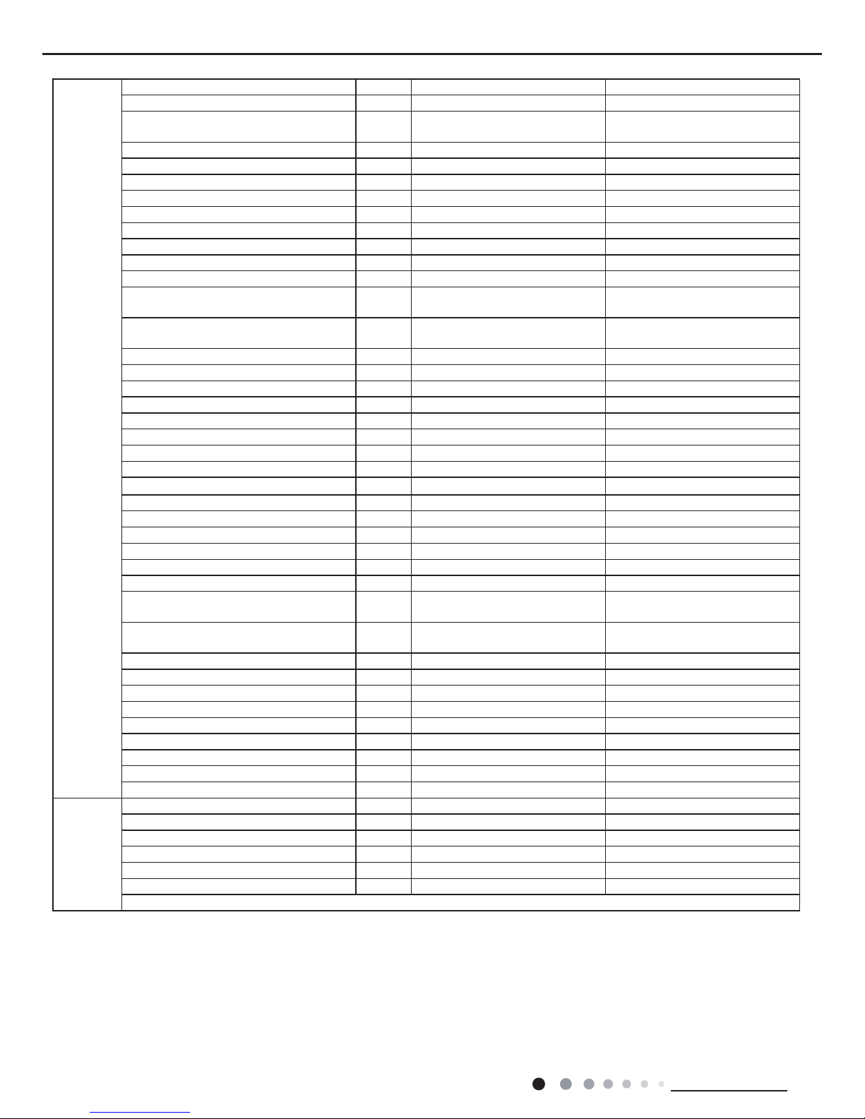
4
Technical Information
Service Manual
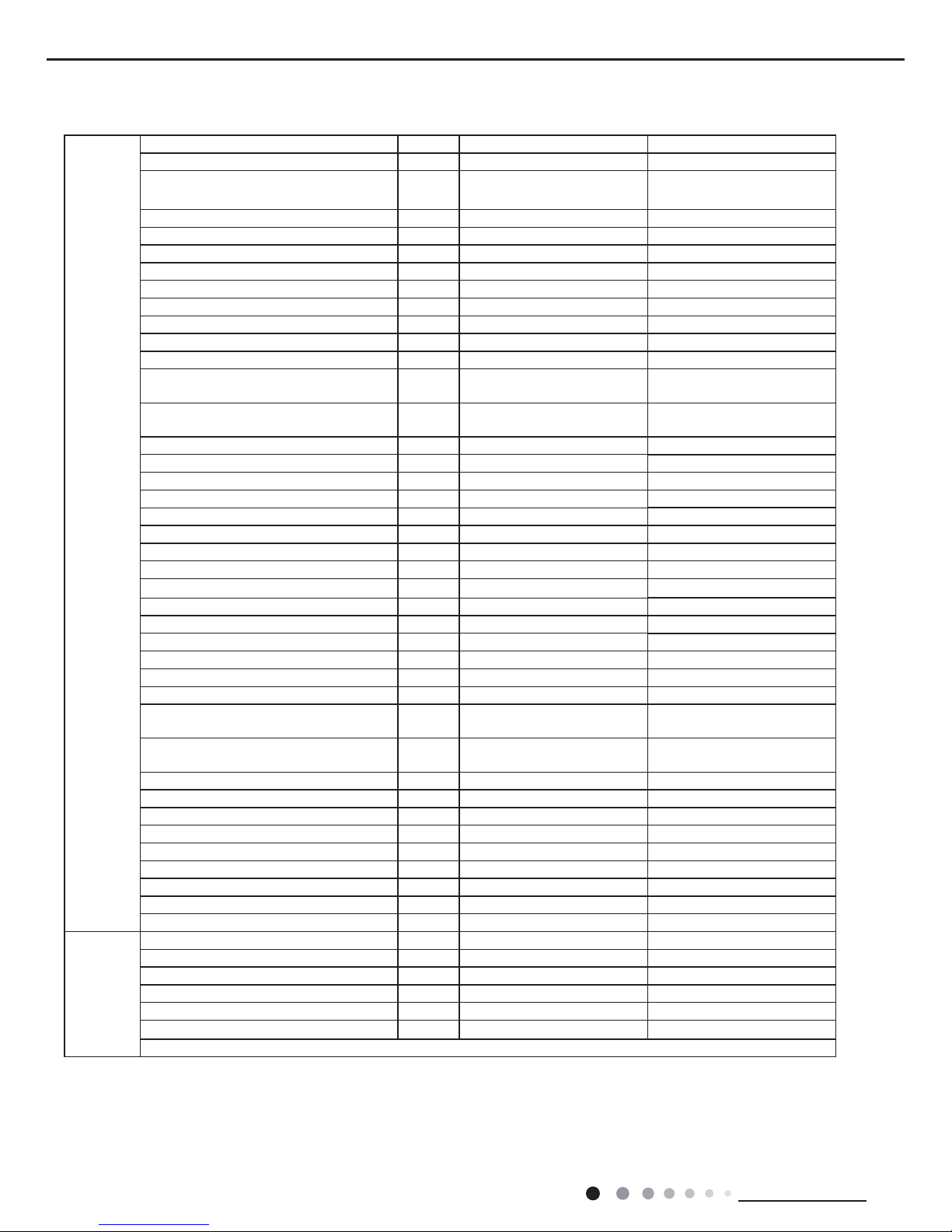
Outdoor
Unit
Outdoor Unit Model GWH09ACC-K6DNA1A/O GWH09ACC-K6DNA1A/O
Outdoor Unit Product Code CB497W03000 CB497W03001
Compressor Manufacturer
ZHUHAI LANDA
COMPRESSOR CO., LTD
ZHUHAI LANDA
COMPRESSOR CO., LTD
Compressor Model QXF-A079zE190A QXF-A079zE190A
Compressor Oil FW68DA FW68DA
Compressor Type Rotary Rotary
Compressor LRA. A / /
Compressor RLA A 4.6 4.6
Compressor Power Input W 790 790
Compressor Overload Protector HPC115/95U1/KSD115
℃
HPC115/95U1/KSD115
℃
Throttling Method Capillary Capillary
Set Temperature Range ºC 16~30 16~30
Cooling Operation Ambient Temperature
Range
ºC -15~43 -15~43
Heating Operation Ambient Temperature
Range
ºC -22~24 -15~24
Condenser Form Aluminum Fin-copper Tube Aluminum Fin-copper Tube
Condenser Pipe Diameter mm Φ7 Φ7
Condenser Rows-n Gap mm 1-1.4 1-1.4
Condenser Coil Length (LXDXW) mm 710X19.05X508 710X19.05X508
Fan Motor Speed rpm 900 900
Fan Motor Power Output W 30 30
Fan Motor RLA A 0.36 0.36
Fan Motor Capacitor μF / /
Outdoor Unit Air Flow Volume m
3
/h 1600 1600
Fan Type Axial-ow Axial-ow
Fan Diameter mm Φ400 Φ400
Defrosting Method Automatic Defrosting Automatic Defrosting
Climate Type T1 T1
Isolation I I
Moisture Protection IPX4 IPX4
Permissible Excessive Operating Pressure
for the Discharge Side
MPa 4.3 4.3
Permissible Excessive Operating Pressure
for the Suction Side
MPa 2.5 2.5
Sound Pressure Level (H/M/L) dB (A) 50/-/- 50/-/-
Sound Power Level (H/M/L) dB (A) 61/-/- 61/-/-
Dimension(WXHXD) mm 782X540X320 782X540X320
Dimension of Carton Box (LXWXH) mm 820X355X580 820X355X580
Dimension of Package(LXWXH) mm 823X358X595 823X358X595
Net Weight kg 27.5 27.5
Gross Weight kg 30 30
Refrigerant R32 R32
Refrigerant Charge kg 0.55 0.55
Connection
Pipe
Connection Pipe Length m 5 5
Connection Pipe Gas Additional Charge g/m 16 16
Outer Diameter Liquid Pipe mm Ф6 Ф6
Outer Diameter Gas Pipe mm Ф9.52 Ф9.52
Max Distance Height m 10 10
Max Distance Length m 15 15
Note: The connection pipe applies metric diameter.
The above data is subject to change without notice. Please refer to the nameplate of the unit.
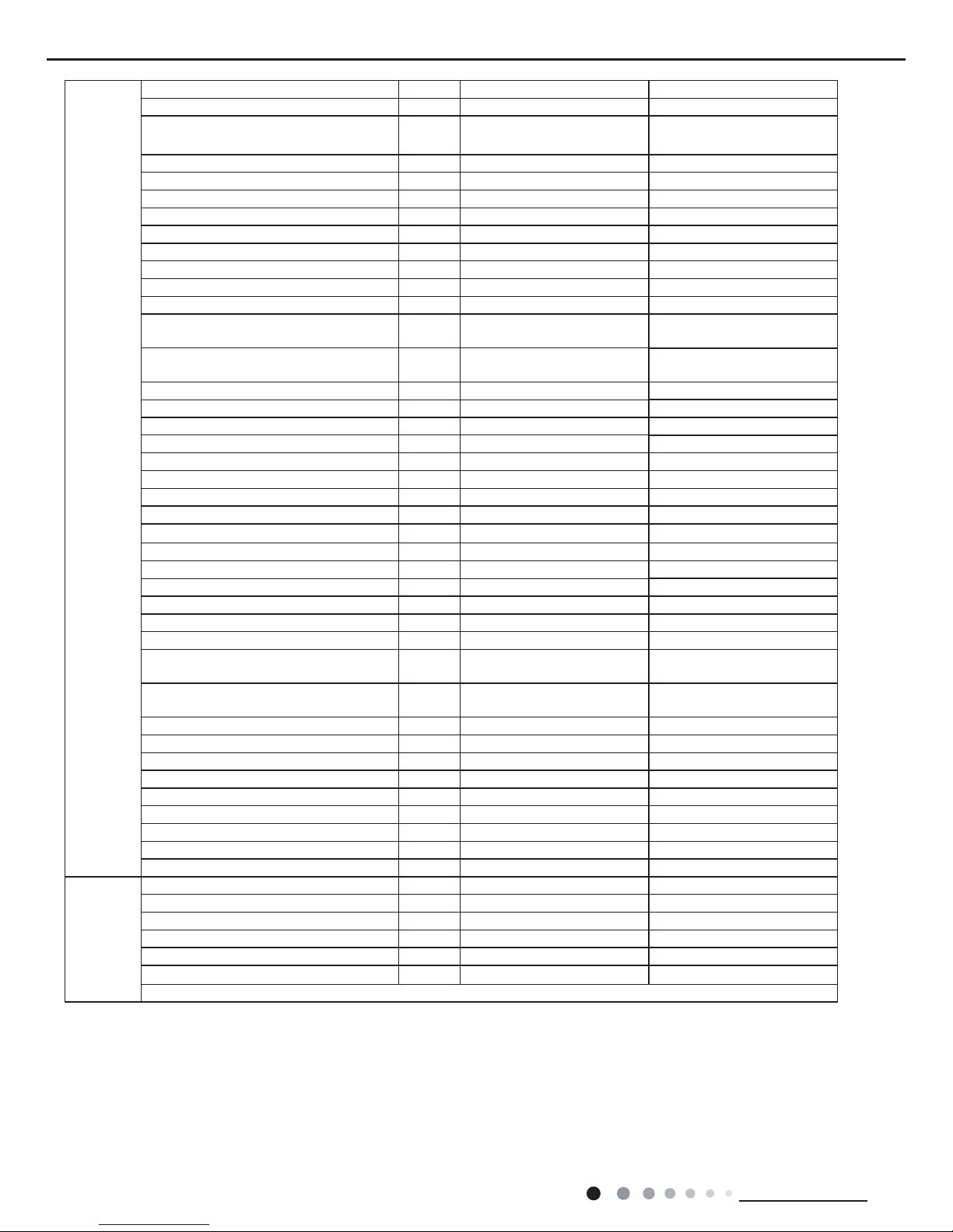
5
Technical Information
Service Manual
Parameter Unit Value
Model
GWH12ACC-K6DNA1D
GWH12ACC-K6DNA4D
GWH12ACC-K6DNA1D
GWH12ACC-K6DNA5D
Product Code
CB497001601/CB497001602
CB344000701
CB497001600
CB341000600
Power
Supply
Rated Voltage V~ 220-240 220-240
Rated Frequency Hz 50 50
Phases 1 1
Power Supply Mode Outdoor Outdoor
Cooling Capacity W 3500 3500
Heating Capacity W 3670 3670
Cooling Power Input W 1085 1085
Heating Power Input W 990 990
Cooling Current Input A 5.0 5.0
Heating Current Input A 4.5 4.5
Rated Input W 1500 1500
Rated Current A 6.6 6.6
Air Flow Volume(SS/H/MH/M/ML/L/SL) m
3
/h 680/620/560/490/450/420/390 680/620/560/490/450/420/390
Dehumidifying Volume L/h 1.4 1.4
EER W/W 3.23 3.23
COP W/W 3.71 3.71
SEER W/W 7 7
SCOP(Average/Warmer/Colder) W/W 4/5.1/3.3 4/5.1/3.3
Application Area m
2
16-24 16-24
Indoor
Unit
Indoor Unit Model
GWH12ACC-K6DNA1D/I
GWH12ACC-K6DNA4D/I
GWH12ACC-K6DNA1D/I
GWH12ACC-K6DNA5D/I
Indoor Unit Product Code
CB497N01600/CB497N01602
CB344N00700
CB497N01600
CB341N00600
Fan Type Cross-ow Cross-ow
Fan Diameter Length(DXL) mm Ф98X633.5 Ф98X633.5
Cooling Speed(SS/H/MH/M/ML/L/SL) r/min 1350/1200/1100/1000/920/850/800 1350/1200/1100/1000/920/850/800
Heating Speed(SS/H/MH/M/ML/L/SL) r/min 1300/1200/1120/1050/980/900/850 1300/1200/1120/1050/980/900/850
Fan Motor Power Output W 20 20
Fan Motor RLA A 0.31 0.31
Fan Motor Capacitor μF 1.5 1.5
Evaporator Form Aluminum Fin-copper Tube Aluminum Fin-copper Tube
Evaporator Pipe Diameter mm Ф5 Ф5
Evaporator Row-n Gap mm 2-1.5 2-1.5
Evaporator Coil Length (LXDXW) mm 635X22.8X306.3 635X22.8X306.3
Swing Motor Model MP24BA MP24BA
Swing Motor Power Output W 1.5 1.5
Fuse Current A 3.15 3.15
Sound Pressure Level(SS/H/MH/M/
ML/L/SL)
dB (A) 42/38/35/32/30/28/26 42/38/35/32/30/28/26
Sound Power Level(SS/H/MH/M/ML/
L/SL)
dB (A) 57/50/47/44/42/40/38 57/50/47/44/42/40/38
Dimension (WXHXD) mm 889X294X212 889X294X212
Dimension of Carton Box (LXWXH) mm 935X349X273 935X349X273
Dimension of Package(LXWXH) mm 940X365X284 940X365X284
Net Weight kg 11 11
Gross Weight kg 13 13
6
Technical Information
Service Manual
Outdoor
Unit
Outdoor Unit Model GWH12QC-K6DNA1D/O GWH12QC-K6DNA1D/O
Outdoor Unit Product Code CB419W15501 CB419W15500
Compressor Manufacturer
ZHUHAI LANDA
COMPRESSOR CO.,LTD
ZHUHAI LANDA
COMPRESSOR CO.,LTD
Compressor Model QXF-A102zE190B QXF-A102zE190B
Compressor Oil FW68DA FW68DA
Compressor Type Rotary Rotary
Compressor LRA. A / /
Compressor RLA A 4.6 4.6
Compressor Power Input W 1023 1023
Compressor Overload Protector HPC115/95U1/KSD115
℃
HPC115/95U1/KSD115
℃
Throttling Method Electron expansion valve Electron expansion valve
Set Temperature Range ºC 16~30 16~30
Cooling Operation Ambient Temperature
Range
ºC -15~43 -15~43
Heating Operation Ambient Temperature
Range
ºC -15~24 -22~24
Condenser Form Aluminum Fin-copper Tube Aluminum Fin-copper Tube
Condenser Pipe Diameter mm Φ7.94 Φ7.94
Condenser Rows-n Gap mm 1-1.4 1-1.4
Condenser Coil Length (LXDXW) mm 731X19.05X550 731X19.05X550
Fan Motor Speed rpm 900 900
Fan Motor Power Output W 30 30
Fan Motor RLA A 0.36 0.36
Fan Motor Capacitor μF / /
Outdoor Unit Air Flow Volume m
3
/h 2200 2200
Fan Type Axial-ow Axial-ow
Fan Diameter mm Ф438 Ф438
Defrosting Method Automatic Defrosting Automatic Defrosting
Climate Type T1 T1
Isolation I I
Moisture Protection IPX4 IPX4
Permissible Excessive Operating Pressure
for the Discharge Side
MPa 4.3 4.3
Permissible Excessive Operating Pressure
for the Suction Side
MPa 2.5 2.5
Sound Pressure Level (H/M/L) dB (A) 52/-/- 52/-/-
Sound Power Level (H/M/L) dB (A) 62/-/- 62/-/-
Dimension(WXHXD) mm 848X596X320 848X596X320
Dimension of Carton Box (LXWXH) mm 878X360X630 878X360X630
Dimension of Package(LXWXH) mm 881X363X645 881X363X645
Net Weight kg 31 31
Gross Weight kg 34 34
Refrigerant R32 R32
Refrigerant Charge kg 0.7 0.7
Connection
Pipe
Connection Pipe Length m 5 5
Connection Pipe Gas Additional Charge g/m 16 16
Outer Diameter Liquid Pipe mm Ф6 Ф6
Outer Diameter Gas Pipe mm Ф9.52 Ф9.52
Max Distance Height m 10 10
Max Distance Length m 20 20
Note: The connection pipe applies metric diameter.
The above data is subject to change without notice. Please refer to the nameplate of the unit.
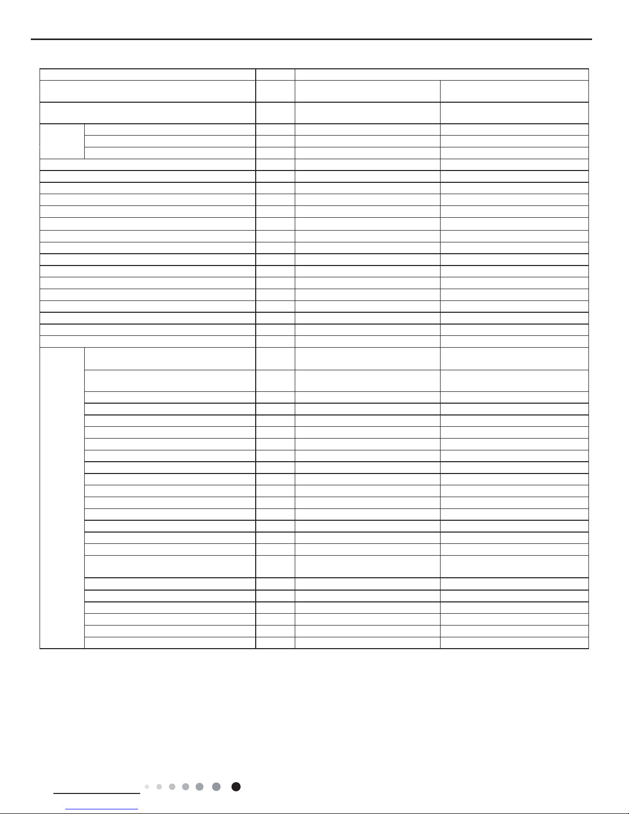
7
Technical Information
Service Manual
Parameter Unit Value
Model
GWH18ACD-K6DNA1D(LCLH)
GWH18ACD-K6DNA5D
GWH18ACD-K6DNA1D(LC)
GWH18ACD-K6DNA4D
Product Code
CB497002100
CB341000700
CB497002101/CB497002102
CB344000901
Power
Supply
Rated Voltage V~ 220-240 220-240
Rated Frequency Hz 50 50
Phases 1 1
Power Supply Mode Outdoor Outdoor
Cooling Capacity W 5200 5200
Heating Capacity W 5300 5300
Cooling Power Input W 1528 1528
Heating Power Input W 1410 1410
Cooling Current Input A 6.78 6.78
Heating Current Input A 6.26 6.26
Rated Input W 2600 2600
Rated Current A 6.78 6.78
Air Flow Volume(SH/H/MH/M/ML/L/SL) m
3
/h 800/720/650/610/570/520/470 800/720/650/610/570/520/470
Dehumidifying Volume L/h 1.8 1.8
EER W/W 3.40 3.4
COP W/W 3.76 3.76
SEER W/W 7 7
SCOP(Average/Warmer/Colder) W/W / /
Application Area m
2
23-34 23-34
Indoor
Unit
Indoor Unit Model
GWH18ACD-K6DNA1D/I
GWH18ACD-K6DNA5D/I
GWH18ACD-K6DNA1D/I
GWH18ACD-K6DNA4D/I
Indoor Unit Product Code
CB497N02100
CB341N00700
CB497N02100/CB497N02102
CB344N00900
Fan Type Cross-ow Cross-ow
Fan Diameter Length(DXL) mm Ф106X706 Ф106X706
Cooling Speed(SH/H/M/L/SL) r/min 1230\1150\1080\980\900\850\800 1230\1150\1080\980\900\850\800
Heating Speed(SH/H/M/L/SL) r/min 1350\1250\1150\1050\980\900\850 1350\1250\1150\1050\980\900\850
Fan Motor Power Output W 35 35
Fan Motor RLA A 0.35 0.35
Fan Motor Capacitor μF 2.5 2.5
Evaporator Form Aluminum Fin-copper Tube Aluminum Fin-copper Tube
Evaporator Pipe Diameter mm Ф7 Ф7
Evaporator Row-n Gap mm 2-1.4 2-1.4
Evaporator Coil Length (LXDXW) mm 715X25.4X304.8 715X25.4X304.8
Swing Motor Model MP35CJ MP35CJ
Swing Motor Power Output W 2.5 2.5
Fuse Current A 3.15 3.15
Sound Pressure Level(SH/H/MH/M/ML/L/
SL)
dB (A) 45/43/41/38/35/34/31 45/43/41/38/35/34/31
Sound Power Level(SH/H/MH/M/ML/L/SL) dB (A) 59/57/55/52/49/48/45 59/57/55/52/49/48/45
Dimension (WXHXD) mm 1013X307X221 1013X307X221
Dimension of Carton Box (LXWXH) mm 1077X375X300 1077X375X300
Dimension of Package(LXWXH) mm 1080X378X315 1080X378X315
Net Weight kg 13.5 13.5
Gross Weight kg 16.5 16.5
8
Technical Information
Service Manual
Outdoor
Unit
Outdoor Unit Model GWH18QD-K6DNA1D/O(LCLH) GWH18QD-K6DNA1D/O(LC)
Outdoor Unit Product Code CB419W15600 CB419W15601
Compressor Manufacturer
ZHUHAI LANDA COMPRESSOR
CO.,LTD
ZHUHAI LANDA COMPRESSOR
CO.,LTD
Compressor Model QXF-B141ZF030F QXF-B141ZF030F
Compressor Oil FW68DA or equivalent FW68DA or equivalent
Compressor Type Rotary Rotary
Compressor LRA. A 25 25
Compressor RLA A 6.5 6.5
Compressor Power Input W 1410 1410
Compressor Overload Protector HPC115/95U1 KSD115
℃
HPC115/95U1 KSD115
℃
Throttling Method Electron expansion valve Electron expansion valve
Set Temperature Range ºC 16~30 16~30
Cooling Operation Ambient Temperature
Range
ºC -15~43 -15~43
Heating Operation Ambient Temperature
Range
ºC -22~24 -15~24
Condenser Form Aluminum Fin-copper Tube Aluminum Fin-copper Tube
Condenser Pipe Diameter mm Φ7 Φ7
Condenser Rows-n Gap mm 2-1.4 2-1.4
Condenser Coil Length (LXDXW) mm 851X38.1X660 851X38.1X660
Fan Motor Speed rpm 800 800
Fan Motor Power Output W 60 60
Fan Motor RLA A 0.4 0.4
Fan Motor Capacitor μF / /
Outdoor Unit Air Flow Volume m
3
/h 3200 3200
Fan Type Axial-ow Axial-ow
Fan Diameter mm Ф520 Ф520
Defrosting Method Automatic Defrosting Automatic Defrosting
Climate Type T1 T1
Isolation I I
Moisture Protection IPX4 IPX4
Permissible Excessive Operating Pressure
for the Discharge Side
MPa 4.3 4.3
Permissible Excessive Operating Pressure
for the Suction Side
MPa 2.5 2.5
Sound Pressure Level (H/M/L) dB (A) 57/-/- 57/-/-
Sound Power Level (H/M/L) dB (A) 64/-/- 64/-/-
Dimension(WXHXD) mm 963X700X396 963X700X396
Dimension of Carton Box (LXWXH) mm 1026X455X735 1026X455X735
Dimension of Package(LXWXH) mm 1029X458X750 1029X458X750
Net Weight kg 45 45
Gross Weight kg 49.5 49.5
Refrigerant R32 R32
Refrigerant Charge kg 1 1
Connection
Pipe
Connection Pipe Length m 5 5
Connection Pipe Gas Additional Charge g/m 16 16
Outer Diameter Liquid Pipe mm Ф6 Ф6
Outer Diameter Gas Pipe mm Ф12 Ф12
Max Distance Height m 10 10
Max Distance Length m 25 25
Note: The connection pipe applies metric diameter.
The above data is subject to change without notice. Please refer to the nameplate of the unit.
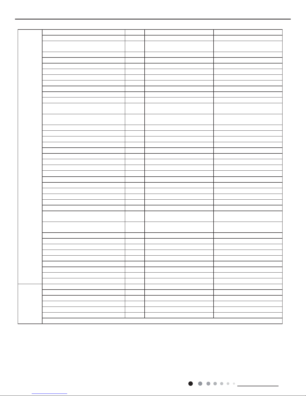
9
Technical Information
Service Manual
Model
GWH24ACE-K6DNA1A
GWH24ACE-K6DNA4A
GWH24ACE-K6DNA1A
Product Code
CB497001901/CB497001903
CB344000801
CB497001900
Power
Supply
Rated Voltage V
~
220-240 220-240
Rated Frequency Hz 50 50
Phases 1 1
Power Supply Mode Outdoor Outdoor
Cooling Capacity W 7000 7000
Heating Capacity W 7400 7400
Cooling Power Input W 1900 1900
Heating Power Input W 1897 1897
Cooling Power Current A 8.73 8.73
Heating Power Current A 8.84 8.84
Rated Input W 3750 3750
Rated Current A 8.73 8.73
Air Flow Volume(SH/H/M/L/SL) m
3
/h 660/590/540/490/450/420/390 660/590/540/490/450/420/390
Dehumidifying Volume L/h 2.4 2.4
EER W/W 3.68 3.68
COP W/W 3.90 3.90
SEER W/W 6.5 6.5
HSPF W/W / /
Application Area m
2
27-42 27-42
Indoor Unit
Model of Indoor Unit
GWH24ACE-K6DNA1A/I
GWH24ACE-K6DNA4A/I
GWH24ACE-K6DNA1A/I
Indoor Unit Product Code
CB497N01900/CB497N01903
CB344N00800
CB497N01900
Fan Type Cross-ow Cross-ow
Diameter Length(DXL) mm Φ108X830 Φ108X830
Fan Motor Cooling Speed(SH/H/M/L/SL) r/min 1250/1150/1050/950/900/850/800 1250/1150/1050/950/900/850/800
Fan Motor Heating Speed(SH/H/M/L/SL) r/min 1250/1150/1050/1000/950/900/850 1250/1150/1050/1000/950/900/850
Output of Fan Motor W 35 35
Fan Motor RLA A 0.35 0.35
Fan Motor Capacitor μF 3 3
Evaporator Form Aluminum Fin-copper Tube Aluminum Fin-copper Tube
Pipe Diameter mm Ф7 Ф7
Row-n Gap mm 2-1.4 2-1.4
Coil Length (LXDXW) mm 850X25.4X342.9 850X25.4X342.9
Swing Motor Model MP35CJ MP35CJ
Output of Swing Motor W 2.5 2.5
Fuse A 3.15 3.15
Sound Pressure Level (SH/H/M/L/SL) dB (A) 48/45/42/39/37/36/33 48/45/42/39/37/36/33
Sound Power Level (SH/H/M/L/SL) dB (A) 58/55/52/49/47/46/43 58/55/52/49/47/46/43
Dimension (WXHXD) mm 1122X329X247 1122X329X247
Dimension of Carton Box (LXWXH) mm 1193X410X350 1193X410X350
Dimension of Package (LXWXH) mm 1148X413X350 1193X410X350
Net Weight kg 17.5 17.5
Gross Weight kg 21 21
10
Technical Information
Service Manual
Outdoor
Unit
Outdoor Unit Model GWH24QE-K6DNA1E/O GWH24QE-K6DNA1E/O
Outdoor Unit Product Code CB419W15701 CB419W15700
Compressor Manufacturer
ZHUHAI LANDA COMPRESSOR
CO., LTD
ZHUHAI LANDA COMPRESSOR
CO., LTD
Compressor Model QXFS-D25zX090H QXFS-D25zX090H
Compressor Oil FW68DA FW68DA
Compressor Type Rotary Rotary
Compressor LRA. A 24 24
Compressor RLA A 11.7 11.7
Compressor Power Input W 2420 2420
Compressor Overload Protector HPC115/95U1/KSD115ºC HPC115/95U1/KSD115ºC
Throttling Method Electron expansion valve Electron expansion valve
Set Temperature Range ºC 16~30 16~30
Cooling Operation Ambient Temperature
Range
ºC -15~43 -15~43
Heating Operation Ambient Temperature
Range
ºC -15~24 -22~24
Condenser Form Aluminum Fin-copper Tube Aluminum Fin-copper Tube
Condenser Pipe Diameter mm Φ7 Φ7
Condenser Rows-n Gap mm 2-1.4 2-1.4
Condenser Coil Length (LXDXW) mm 935X38.1X660 935X38.1X660
Fan Motor Speed rpm 800 800
Fan Motor Power Output W 60 60
Fan Motor RLA A 0.58 0.58
Fan Motor Capacitor μF / /
Outdoor Unit Air Flow Volume m
3
/h 3200 3200
Fan Type Axial-ow Axial-ow
Fan Diameter mm Ф520 Ф520
Defrosting Method Automatic Defrosting Automatic Defrosting
Climate Type T1 T1
Isolation I I
Moisture Protection IPX4 IPX4
Permissible Excessive Operating Pressure
for the Discharge Side
MPa 4.3 4.3
Permissible Excessive Operating Pressure
for the Suction Side
MPa 2.5 2.5
Sound Pressure Level (H/M/L) dB (A) 57/-/- 57/-/-
Sound Power Level (H/M/L) dB (A) 67/-/- 67/-/-
Dimension(WXHXD) mm 963X700X396 963X700X396
Dimension of Carton Box (LXWXH) mm 1026X455X735 1026X455X735
Dimension of Package(LXWXH) mm 1029X458X750 1029X458X750
Net Weight kg 53.5 53.5
Gross Weight kg 58 58
Refrigerant R32 R32
Refrigerant Charge kg 1.7 1.7
Connection
Pipe
Connection Pipe Length m 5 5
Connection Pipe Gas Additional Charge g/m 50 50
Outer Diameter Liquid Pipe mm Ф6 Ф6
Outer Diameter Gas Pipe mm Ф16 Ф16
Max Distance Height m 10 10
Max Distance Length m 20 20
Note: The connection pipe applies metric diameter.
The above data is subject to change without notice. Please refer to the nameplate of the unit.
11
Technical Information
Service Manual
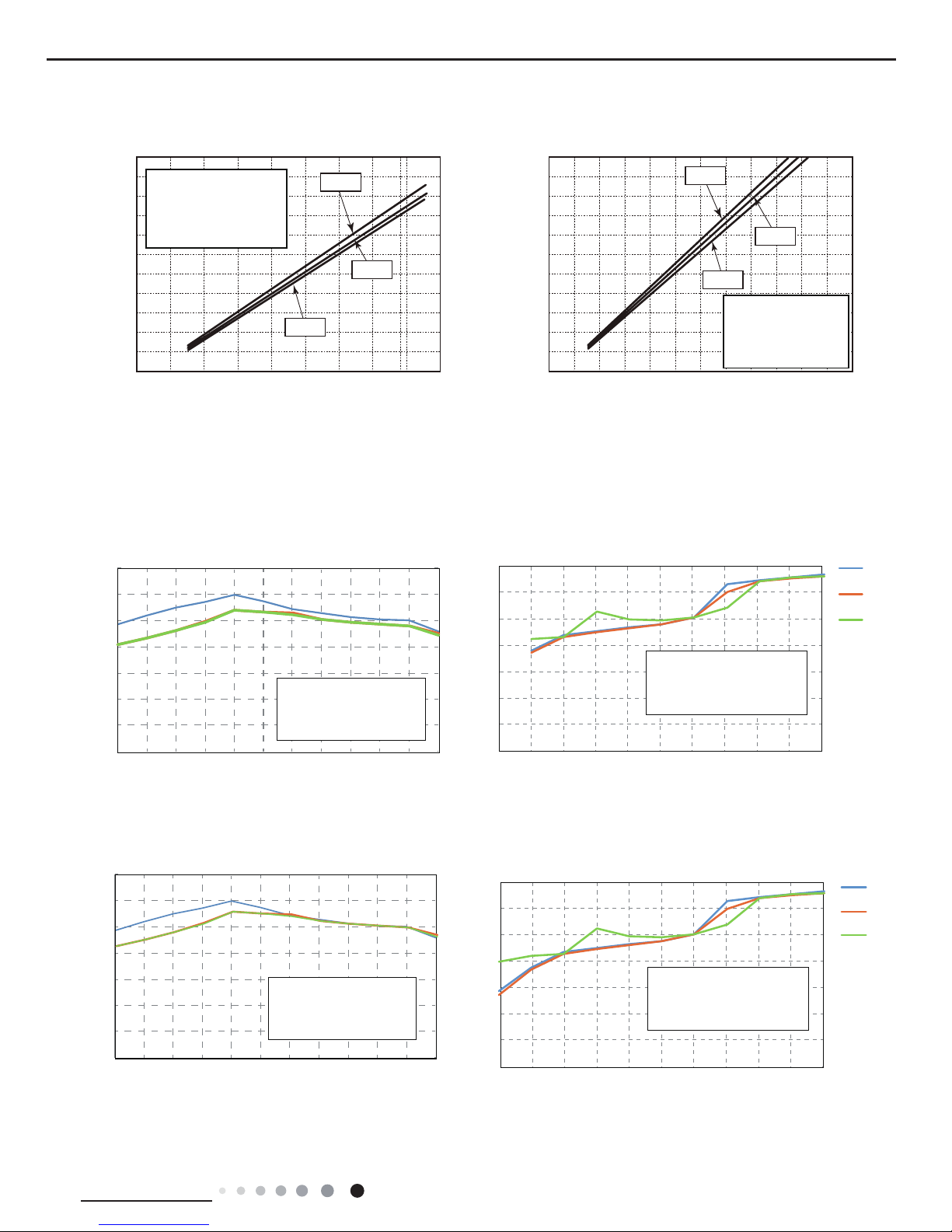
2.2 Operation Characteristic Curve
2.3 Capacity Variation Ratio According to Temperature
01020304050607090010 20 30 40 50 60 70 80 90 100 120 110
80
11
10
9
8
7
6
5
4
3
2
1
0
Compressor speed (rps)
) A ( t n e r r u C
11
10
9
8
7
6
5
4
3
2
1
0
Compressor speed (rps)
) A ( t n e r r u C
220V
230V
240V
220V
230V
240V
01020304050607090010 20 30 40 50 60 70 80 90 100
120
110
80
11
10
9
8
7
6
5
4
3
2
1
0
Compressor speed (rps)
)A(tnerruC
11
10
9
8
7
6
5
4
3
2
1
0
Compressor speed (rps)
)A(tnerruC
220V
230V
240V
220V
230V
240V
Conditions
Indoor: DB27°C/WB19°C
Outdoor: DB35°C/WB24°C
Indoor air flow: High
Pipe length: 5m
Conditions
Indoor: DB27°C/WB19°C
Outdoor: DB35°C/WB24°C
Indoor air flow: High
Pipe length: 5m
Conditions
Indoor: DB20°C/WB15°C
Outdoor: DB7°C/WB6°C
Indoor air flow: High
Pipe length: 5m
Conditions
Indoor: DB20°C/WB15°C
Outdoor: DB7°C/WB6°C
Indoor air flow: High
Pipe length: 5m
Cooling Heating
Capacity ratio(%)
gnilooC
gnilooC
Outdoor temp.(°C)
Capacity ratio(%)
Outdoor temp.(°C)
gnitaeH
Capacity ratio(
%)
Outdoor temp.(°C)
gnitaeH
Capacity ratio(
%)
Outdoor temp.(°C)
Heating operation ambient temperature range is -15ºC~24ºC
Heating operation ambient temperature range is -22ºC~24ºC
0
20
40
60
80
100
120
140
-15-10 -5 0510 15 20 25 30 35 43
0
20
40
60
80
100
120
140
-15-10 -5 0510 15 20 25 30 35 43
0
20
40
60
80
100
120
140
-22 -15 -10 -7 0 2 7 15 18 21 24
Conditions
Indoor:DB20°C
Indoor air flow:Super High
Pipe length:5m
0
20
40
60
80
100
120
140
-22 -15 -10 -7 0 2 7 15 18 21 24
Conditions
Indoor:DB20°C
Indoor air flow:Super High
Pipe length:5m
Condition
Indoor:DB27°C WB19°C
Indoor air flow:
High
Pipe length:5m
Condition
Indoor:DB27°C WB19°C
Indoor air flow:
High
Pipe length:5m
09/12K
18K
24K
09/12K
18K
24K
12
Technical Information
Service Manual
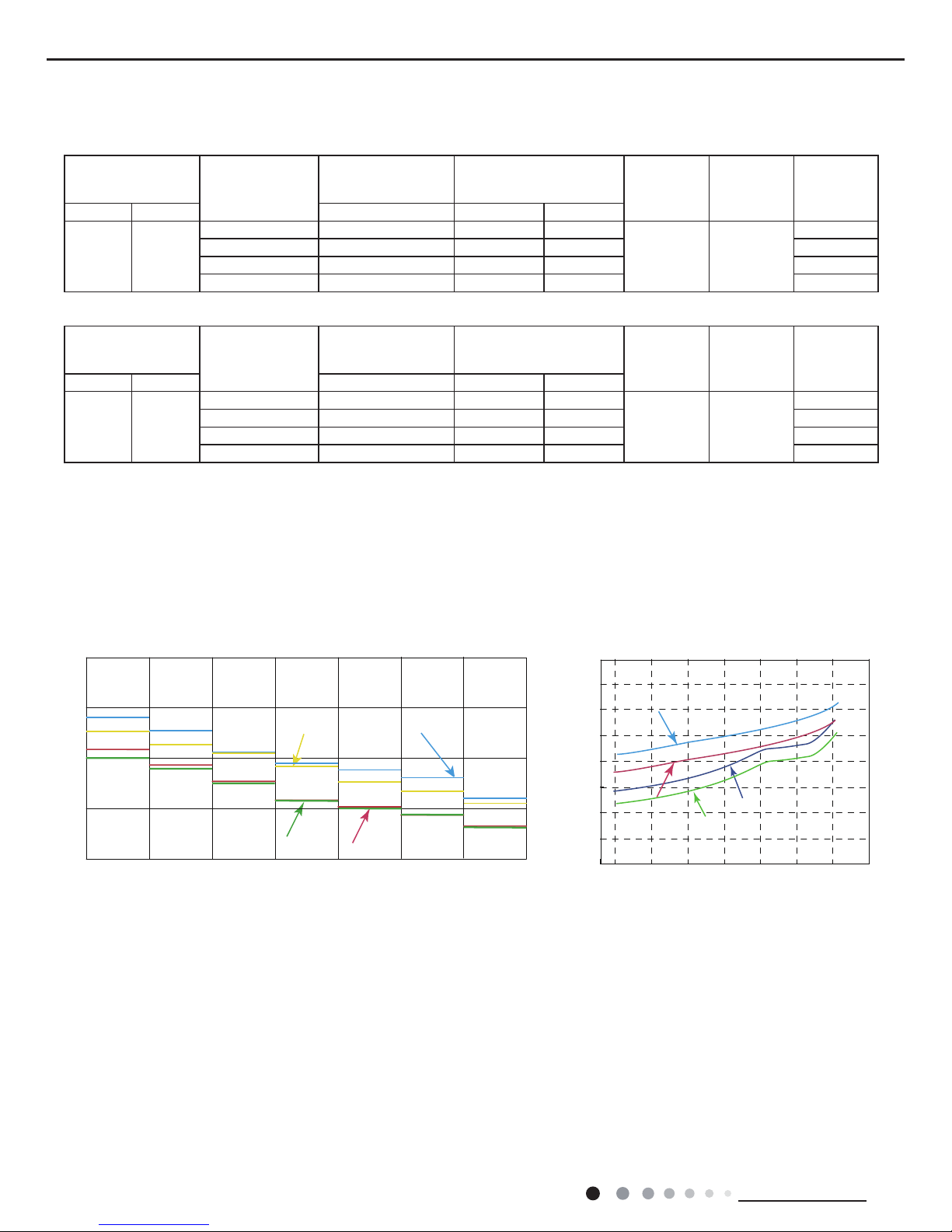
2.4 Cooling and Heating Data Sheet in Rated Frequency
2.5 Noise Curve
Indoor side noise when blowing Outdoor side noise when blowing
Indoor fan motor rotating speed
Compressor frequency(Hz)
Noise/dB(A)
50
60
30
40
20
Turbo
High
Medium-high
Medium
Medium-low
Low
Ultralow
40
42
44
46
48
50
52
54
56
20 4030 50 60 70 80 90
Noise dB(A)
18K
12K
09K
12K
09K
18K
24K
24K
Cooling:
Rated cooling
condition(°C) (DB/WB)
Model
Pressure of gas pipe
connecting indoor and
outdoor unit
Inlet and outlet pipe
temperature of heat
exchanger
Fan speed of
indoor unit
Fan speed of
outdoor unit
Compressor
revolution
(rps)
Indoor Outdoor P (MPa) T1 (°C) T2 (°C)
27/19 35/24
09K 0.8 ~ 1.1 12 to 15 65 to 38
TURBO High
57
12K 0.8 ~ 1.1 11 to 14 64 to 37 60
18K 0.9 ~ 1.1 12 to 14 75 to 37 52
24K 0.9 ~ 1.1 12 to 14 75 to 37 72
Instruction:
T1: Inlet and outlet pipe temperature of evaporator
T2: Inlet and outlet pipe temperature of condenser
P: Pressure at the side of big valve
Connection pipe length: 5 m.
Heating:
Rated cooling
condition(°C) (DB/WB)
Model
Pressure of gas pipe
connecting indoor and
outdoor unit
Inlet and outlet pipe
temperature of heat
exchanger
Fan speed of
indoor unit
Fan speed of
outdoor unit
Compressor
revolution
(rps)
Indoor Outdoor P (MPa) T1 (°C) T2 (°C)
20/- 7/6
09K 2.8 ~ 3.2 35 to 63 2 to 5
TURBO High
64
12K 2.8 ~ 3.2 35 to 65 2 to 5 67
18K 2.2 ~ 2.4 70 to 35 2 to 4 65
24K 2.2 ~ 2.4 70 to 35 2 to 4 77
13
Technical Information
Service Manual
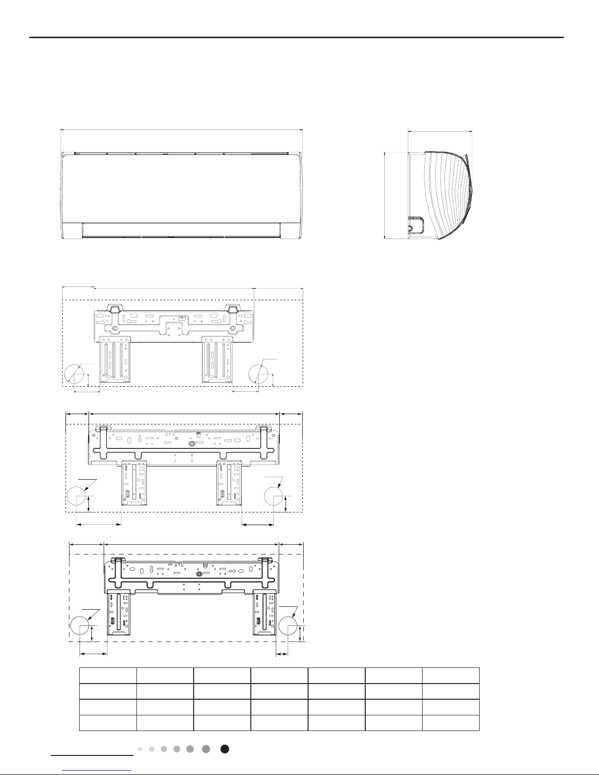
3. Outline Dimension Diagram
3.1 Indoor Unit
Unit:mm
Models W H D W1 W2 W3
09/12K 889 294 212 201.5 541.5 146
18K 1013 307 221 125.5 685 202.5
24K 1122 329 247 207 685 230
09/12K
18K
24K
Unit:mm
D
H
W
75
35
Φ55
W3W2
W1
Φ55
35
75
D
H
W
W1 W2 W3
140
190
38
Φ55
Φ55
38
W
D
H
79
154
43
W1 W2 W3
Φ70
Φ70
43
14
Technical Information
Service Manual
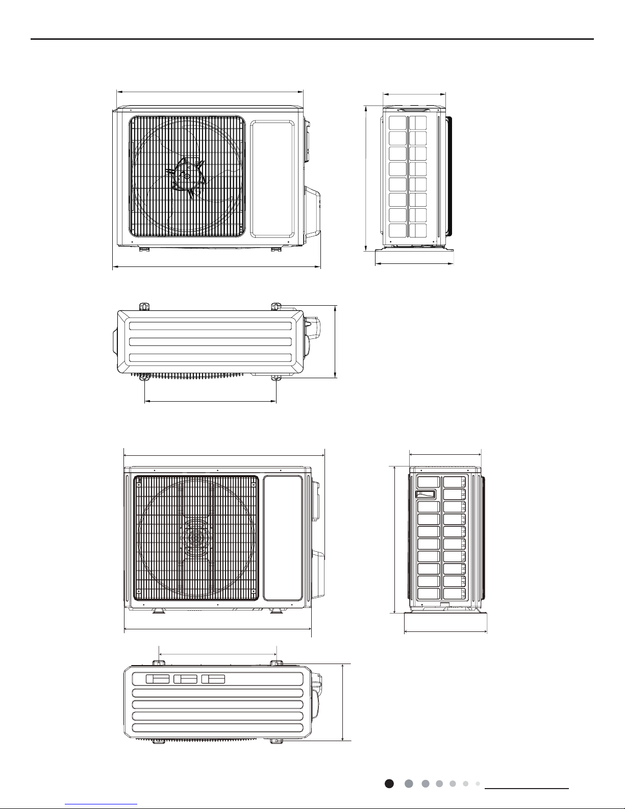
3.2 Outdoor Unit
780
596
848
286
540
257
320
Unit:mm
12K
18/24K
340
963
700
396
890
560
364
Unit:mm
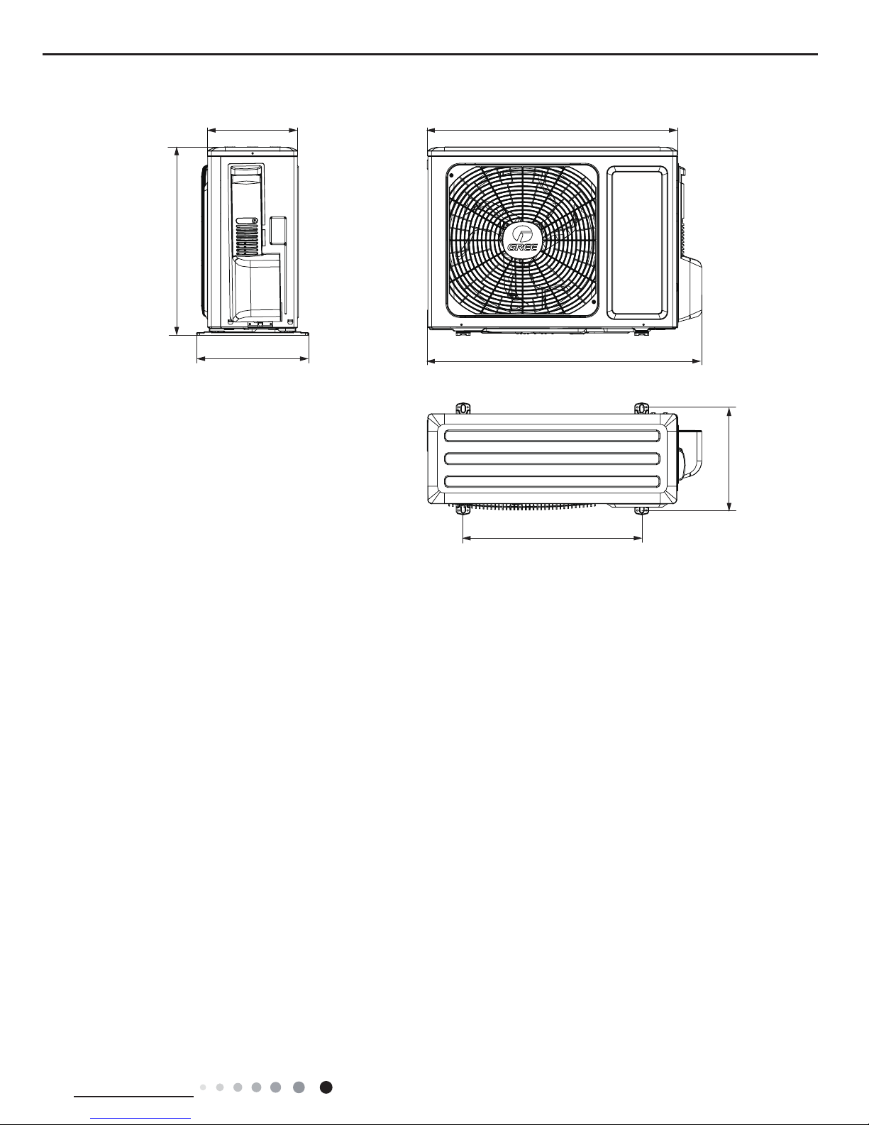
15
Technical Information
Service Manual
Unit:mm
09K
712
782
257
320
540
286
510
16
Technical Information
Service Manual
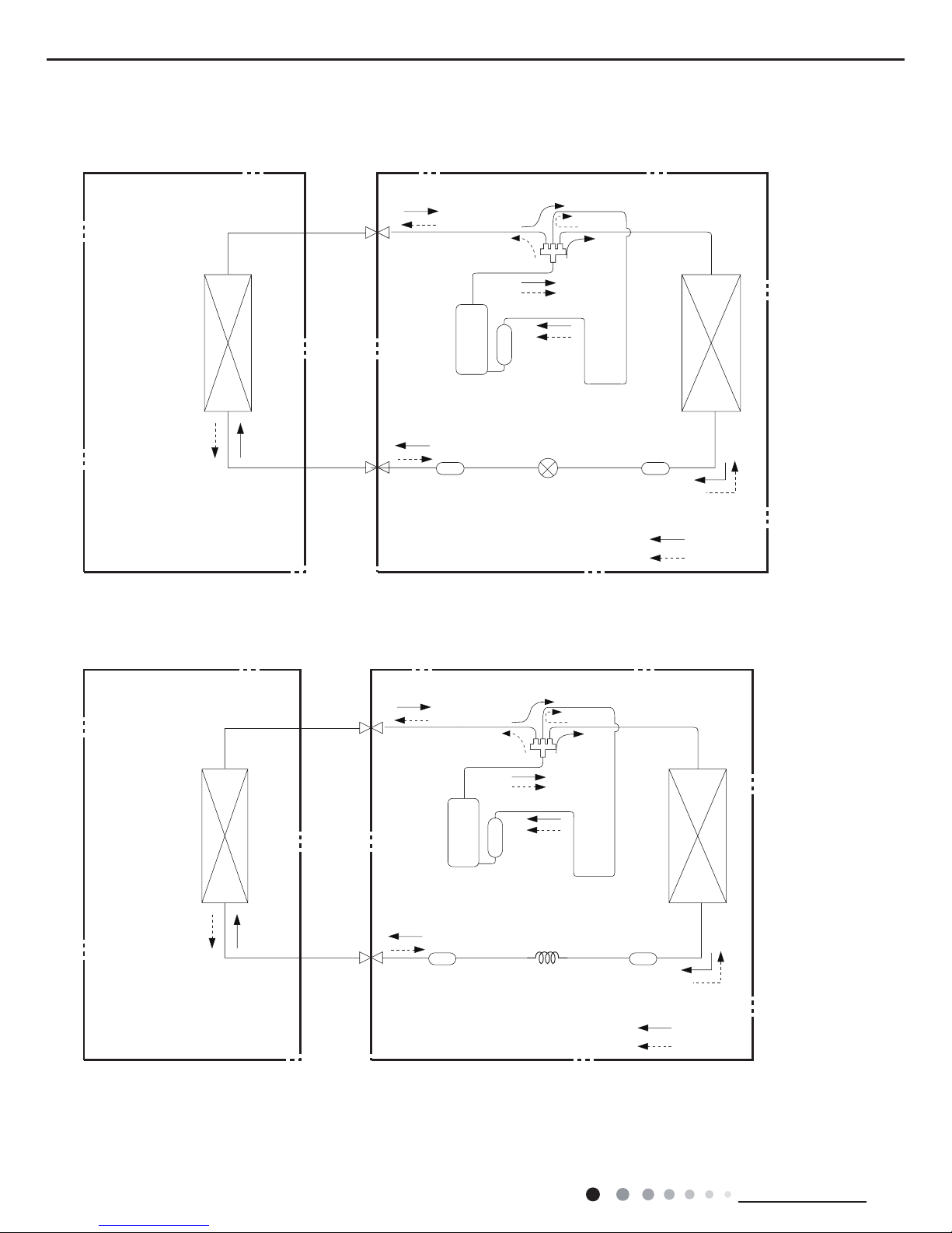
4. Refrigerant System Diagram
Indoor unit
Outdoor unit
COOLING
HEATING
4-Way valve
Discharge
Suction
Heat
exchanger
(evaporator)
Heat
exchanger
(condenser)
Valve
Valve
Liquid pipe
side
Gas pipe
side
Strainer Electric
expand
valve
Strainer
Compressor
Accumlator
Connection pipe specication:
Liquid pipe:1/4" (6mm)
Gas pipe:3/8" (9.52mm) 09/12K
Gas pipe:1/2" (12mm) 18K
Gas pipe:5/8" (16mm) 24K
Indoor unit
Outdoor unit
COOLING
HEATING
4-Way valve
Discharge
Suction
Heat
exchanger
(evaporator)
Heat
exchanger
(condenser)
Valve
Valve
Liquid pipe
side
Gas pipe
side
Strainer
Strainer
Capillary
Accumlator
Compressor
Cooling and heating model
Cooling and heating model
09K
12/18/24K
17
Technical Information
Service Manual
5. Electrical Part
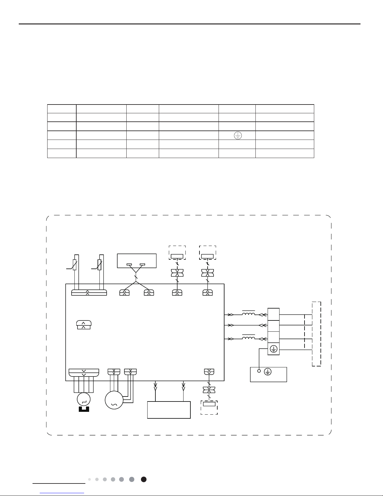
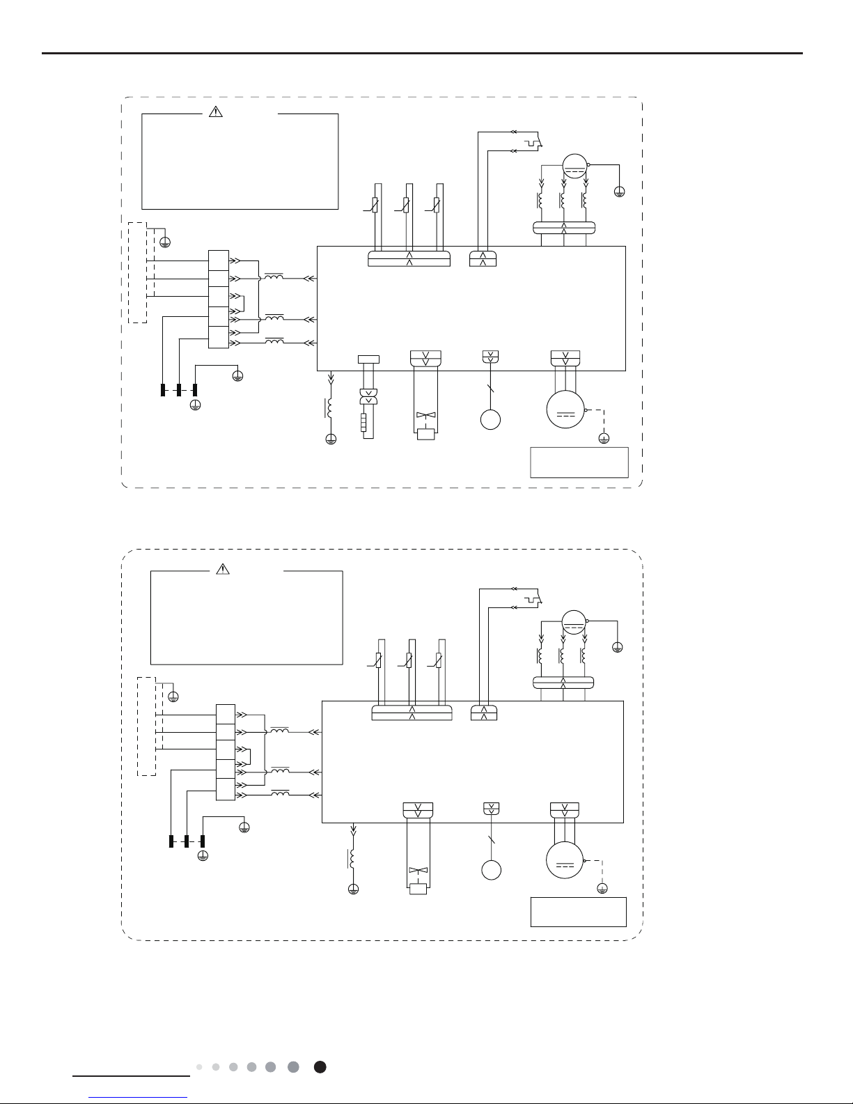
5.1 Wiring Diagram
● Indoor Unit
● Instruction
Symbol Symbol Color Symbol Symbol Color Symbol Name
WH White GN Green CAP Jumper cap
YE Yellow BN Brown COMP Compressor
RD Red BU Blue Grounding wire
YEGN Yellow/Green BK Black / /
VT Violet OG Orange / /
Note: Jumper cap is used to determine fan speed and the swing angle of horizontal lover for this model.
60000700068803
:,5('
&21752//(5
&200$18$/
76(1625
7(03
6(1625
7(03
6(1625
57
522078%(
67(33,1*
',63/$<
35,17('&,5&8,7%2$5'
5(&(,9(5$1'
',63/$<%2$5'
&$%/(
&211(&7,1*
6:,1*8'
02725
%/2&.
7(50,1$/
$3
-803
&$3
%8
%.
<(*1
(9$325$725
3(
;7
1
0
287'22581,7
$3
3*
*(1(5$725
&2/'3/$60$
)$102725
0
5' %8
+($/7+1
+($/7+/
3*)
',63 ',63
%1
<(*1
57
1
&20287
$&/
%8
%.
%1
/
/
:,),
02'8/(
:,),
$3
$3
$3
'5<&
'225&
237,21$/
'5<&217$&7
0$*1(7,&
5,1*
18
Technical Information
Service Manual
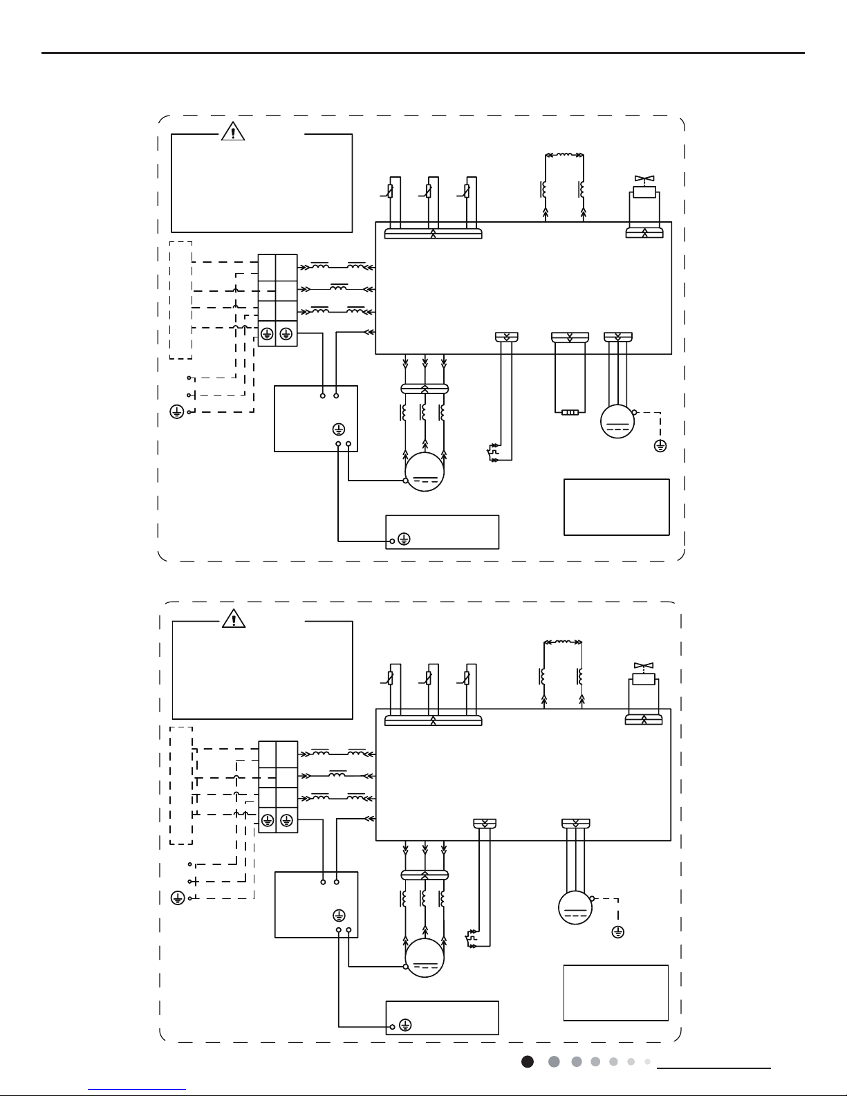
60000700068702
● Outdoor Unit
RIHOHFWULFVKRFN
3OHDVHGRQWWRXFKDQ\
WHUPLQDOZKHQWKHPDFKLQHLV
UXQQLQJVWRSSLQJRUKDVEHHQ
SRZHUHGRIIIRUOHVVWKDQ
PLQXWHVWRSUHYHQWWKHULVN
:$51,1*
<(*1
%8
%.
%1
1
/
1
/
/
/
/
%8
%1
0$*1(7,&5,1*
7(50,1$/
;7
%/2&.
1
$&/
&208
3(
&1
7(03
6(1625
7(03
6(1625
7(03
57
57
57
6(1625
N
N
N
28778%(
2875220
(;+$867
<9
:$<
:$<
9$/9(
97
97
/;
/;
/
/
5($&725
/
%8
%1
0$*1(7,&
5,1*
$30DLQ%RDUG
(+
%RWWRP
%DQG
+HDWHU
+($7
2)$1
)$1
0
3(
3(
<(*1
02725
3527(&725
29(5/2$'
5'
29&&203
6$7
5'
/
:
9
8
&203
&203
:
9
8
;
%8
<(
5'
0$*1(7,&
5,1*
32:(5
/
1
<(*1
%8
%1%.
<(*1
<(*1
3(
<(*1
(/(&75,&$/
%2;
3(
0,',62/$7,21
6+((7
3(
<(*1
%8
<(
5'
%.
/
127(0RWRU
DSSOLHVWRWKH
LURQVKHOOPRWRU
JURXQGRQO\
,1'22581,7
GWH09ACC-K6DNA1A/O(CB497W03000)
GWH09ACC-K6DNA1A/O(CB497W03001)
600007000687
RIHOHFWULFVKRFN
3OHDVHGRQWWRXFKDQ\
WHUPLQDOZKHQWKHPDFKLQHLV
UXQQLQJVWRSSLQJRUKDVEHHQ
SRZHUHGRIIIRUOHVVWKDQ
PLQXWHVWRSUHYHQWWKHULVN
:$51,1*
<(*1
%8
%.
%1
1
/
1
/
/
/
/
%8
%.
%1
0$*1(7,&5,1*
7(50,1$/
;7
%/2&.
1
$&/
&208
3(
&1
7(03
6(1625
7(03
6(1625
7(03
57
57
57
6(1625
N
N
N
28778%(
2875220
(;+$867
<9
:$<
:$<
9$/9(
97
97
/;/;
/
/
5($&725
/
%8
%1
0$*1(7,&
5,1*
$30DLQ%RDUG
2)$1
)$1
0
3(
3(
<(*1
02725
3527(&725
29(5/2$'
5'
29&&203
6$7
5'
/
:
9
8
&203
&203
:
9
8
;
%8
<(
5'
0$*1(7,&
5,1*
32:(5
/
1
<(*1
%8
%1%.
<(*1
<(*1
3(
<(*1
(/(&75,&$/
%2;
3(
0,',62/$7,21
6+((7
3(
<(*1
%8
<(
5'
127(0RWRU
DSSOLHVWRWKH
LURQVKHOOPRWRU
JURXQGRQO\
,1'22581,7
/
19
Technical Information
Service Manual
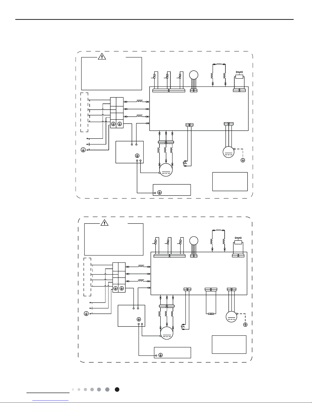
60000700111002
GWH12QC-K6DNA1D/O(LC)(CB419W15501)
GWH12QC-K6DNA1D/O(LCLH) (CB419W15500)
60000700111001
,1'22581,7
127(0RWRU
DSSOLHVWRWKH
LURQVKHOOPRWRU
JURXQGRQO\
RIHOHFWULFVKRFN
3OHDVHGRQWWRXFKDQ\
WHUPLQDOZKHQWKHPDFKLQHLV
UXQQLQJVWRSSLQJRUKDVEHHQ
SRZHUHGRIIIRUOHVVWKDQ
PLQXWHVWRSUHYHQWWKHULVN
:$51,1*
<(*1
%8
%.
%1
1
/
1
/
/
%8
%.
%1
0$*1(7,&5,1*
7(50,1$/
;7
%/2&.
1
$&/
&208
3(
&1
7(03
6(1625
7(03
6(1625
7(03
57
57
57
6(1625
N
N
N
28778%(
2875220
(;+$867
&1
(.9
(/(&7521,&
9$/9(
(;3$16,21
<9
:$<
:$<
9$/9(
97
97
/;
/;
/
/
5($&725
/
%8
%1
0$*1(7,&
5,1*
$30DLQ%RDUG
2)$1
)$1
0
3(
3(
<(*1
02725
3527(&725
29(5/2$'
5'
29&&203
6$7
5'
/
:
9
8
&203
&203
:
9
8
;
%8
<(
5'
0$*1(7,&
5,1*
32:(5
/
1
<(*1
%8
%1%.
<(*1
<(*1
3(
<(*1
(/(&75,&$/
%2;
3(
<(*1
%8
<(
5'
0,',62/$7,21
6+((7
3(
,1'22581,7
127(0RWRU
DSSOLHVWRWKH
LURQVKHOOPRWRU
JURXQGRQO\
RIHOHFWULFVKRFN
3OHDVHGRQWWRXFKDQ\
WHUPLQDOZKHQWKHPDFKLQHLV
UXQQLQJVWRSSLQJRUKDVEHHQ
SRZHUHGRIIIRUOHVVWKDQ
PLQXWHVWRSUHYHQWWKHULVN
:$51,1*
<(*1
%8
%.
%1
1
/
1
/
/
%8
%.
%1
0$*1(7,&5,1*
7(50,1$/
;7
%/2&.
1
$&/
&208
3(
&1
7(03
6(1625
7(03
6(1625
7(03
57
57
57
6(1625
N
N
N
28778%(
2875220
(;+$867
&1
(.9
(/(&7521,&
9$/9(
(;3$16,21
<9
:$<
:$<
9$/9(
97
97
/;
/;
/
/
5($&725
/
%8
%1
0$*1(7,&
5,1*
$30DLQ%RDUG
(+
%RWWRP
%DQG
+HDWHU
+($7
2)$1
)$1
0
3(
3(
<(*1
02725
3527(&725
29(5/2$'
5'
29&&203
6$7
5'
/
:
9
8
&203
&203
:
9
8
;
%8
<(
5'
0$*1(7,&
5,1*
32:(5
/
1
<(*1
%8
%1%.
<(*1
<(*1
3(
<(*1
(/(&75,&$/
%2;
3(
<(*1
%8
<(
5'
0,',62/$7,21
6+((7
3(
20
Technical Information
Service Manual
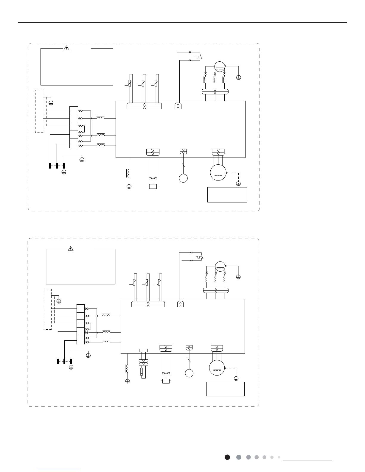
GWH18QD-K6DNA1D/O(CB419W15600)
3OHDVHGRQWWRXFKDQ\
WHUPLQDOZKHQWKHYROWDJH
RIWHUPLQDO3'&DQG
1'&DW$3LVKLJKHU
WKDQ9WRSUHYHQWWKH
ULVNRIHOHFWULFVKRFN
:$51,1*
&20B,11(5
1
$&B/
5'
%$1'
+($7(5
%27720
5'
(+
+($7B%
1/
<(*1
%8
3(
1
/
1
%1
%.
%8
;7
,1'22581,7
/
5,1*
%.
%1
%8
%1
%8
<(*1
%/2&.
7(50,1$/
3(
0$*1(7,&
/
/
32:(5
%1%.
/
35,17('&,5&8,7%2$5'
:$< )$
7979
9$/9(
<9
:$<
(.9
(OHFWURQLF
([SDQVLRQ
9DOYH
3(
<(*1
3(
$3
7B6(1625
:5'9<(8%8
29&B&203
. ..
&203
:
9
8
/ /
5,1*
0$*1(7,&
/
29(5/2$'3527(&725
<(*1
<(%8
5'
3(
3(
57 57 57
5'
+:+:
6$7
&203
;
<(%8
:+ %.
7(036(1625
28778%(
2875220
7(036(1625
(;+$867
7(036(1625
3(
0
2)$1
)$102725
<(*1
3(
LURQVKHOOPRWRU
RQO\DSSOLHVWRWKH
1RWH0RWRUJURXQG
6361000021801
GWH18QD-K6DNA1D/O(CB419W15601)
$&B/
1
&20B,11(5
:$51,1*
3OHDVHGRQWWRXFKDQ\
WHUPLQDOZKHQWKHYROWDJH
RIWHUPLQDO3'&DQG
1'&DW$3LVKLJKHU
WKDQ9WRSUHYHQWWKH
ULVNRIHOHFWULFVKRFN
$3
7(036(1625
(;+$867
7(036(1625
2875220
28778%(
7(036(1625
%.:+
%8 <(
;
&203
6$7
:+ :+
29&B&203
5'
575757
3(
3(
5'%8 <(
8%8 9<( :5'
<(*1
29(5/2$'3527(&725
/
0$*1(7,&
5,1*
//
3(
<(*1
3(
9DOYH
([SDQVLRQ
(OHFWURQLF
(.9
3(
0
:$<
<9
9$/9(
97 97
)$ 2)$1:$<
)$102725
<(*1
3(
35,17('&,5&8,7%2$5'
8
9
:
/
&203
7B6(1625
%1%.
32:(5
/
/
0$*1(7,&
3(
7(50,1$/
%/2&.
<(*1
%8
%1
%8
%1
%.
5,1*
/
,1'22581,7
;7
%8
%.
%1
1
/
1
3(
%8
<(*1
/1
...
LURQVKHOOPRWRU
RQO\DSSOLHVWRWKH
1RWH0RWRUJURXQG
63610000218
21
Technical Information
Service Manual
60000700033902
GWH24QE-K6DNA1E/O(CB419W15700)
3OHDVHGRQWWRXFKDQ\
HOHFWURQLFFRPSRQHQWRU
WHUPLQDOZKHQWKHPDFKLQHLV
UXQQLQJVWRSSLQJRUKDV
EHHQSRZHUHGRIIIRUOHVV
WKDQPLQXWHVWRSUHYHQW
WKHULVNRIHOHFWULFVKRFN
:$51,1*
&20,11(5
1
$&B/
1
/
<(*1
%8
3(
1
/
1
%1
%.
%8
;7
,1'22581,7
5,1*
%1
%8
%/2&.
7(50,1$/
0$*1(7,&
32:(5
%1%.
76(1625
&203
/
:
9
8
35,17('&,5&8,7%2$5'
3(
<(*1
)$102725
:$< 2)$1)$
7979
9$/9(
<9
:$<
0
3(
(.9
(OHFWURQLF
([SDQVLRQ
9DOYH
3(
<(*1
3(
5,1*
0$*1(7,&
29(5/2$'3527(&725
<(*1
:5'9<(8%8
8%(<
5'
3(
3(
57 57 57
5'
29&&203
+:+:
6$7
&203
;
8%(<
:+ %.
7(036(1625
28778%(
2875220
7(036(1625
(;+$867
7(036(1625
$3
...
<(*1
3(
/
/
%8
%1
%.
/
5,1*
0$*1(7,&
/ /
/
LURQVKHOOPRWRU
RQO\DSSOLHVWRWKH
127(0RWRUJURXQG
+($7%
(+
5'
%27720
+($7(5
%$1'
5'
3OHDVHGRQWWRXFKDQ\
HOHFWURQLFFRPSRQHQWRU
WHUPLQDOZKHQWKHPDFKLQHLV
UXQQLQJVWRSSLQJRUKDV
EHHQSRZHUHGRIIIRUOHVV
WKDQPLQXWHVWRSUHYHQW
WKHULVNRIHOHFWULFVKRFN
:$51,1*
&20,11(5
1
$&B/
1/
<(*1
%8
3(
1
/
1
%1
%.
%8
;7
,1'22581,7
5,1*
%1
%8
%/2&.
7(50,1$/
0$*1(7,&
32:(5
%1%.
76(1625
&203
/
:
9
8
35,17('&,5&8,7%2$5'
3(
<(*1
)$102725
:$< 2)$1)$
7979
9$/9(
<9
:$<
0
3(
(.9
(OHFWURQLF
([SDQVLRQ
9DOYH
3(
<(*1
3(
5,1*
0$*1(7,&
29(5/2$'3527(&725
<(*1
:5'9<(8%8
8%(<
5'
3(
3(
57 57 57
5'
29&&203
+:+:
6$7
&203
;
8%(<
:+ %.
7(036(1625
28778%(
2875220
7(036(1625
(;+$867
7(036(1625
$3
...
<(*1
3(
/
/
%8
%1
%.
/
5,1*
0$*1(7,&
/ /
/
LURQVKHOOPRWRU
RQO\DSSOLHVWRWKH
127(0RWRUJURXQG
600007000339
GWH24QE-K6DNA1E/O(CB419W15701)
These circuit diagrams are subject to change without notice, please refer to the one supplied with the unit.
22
Technical Information
Service Manual
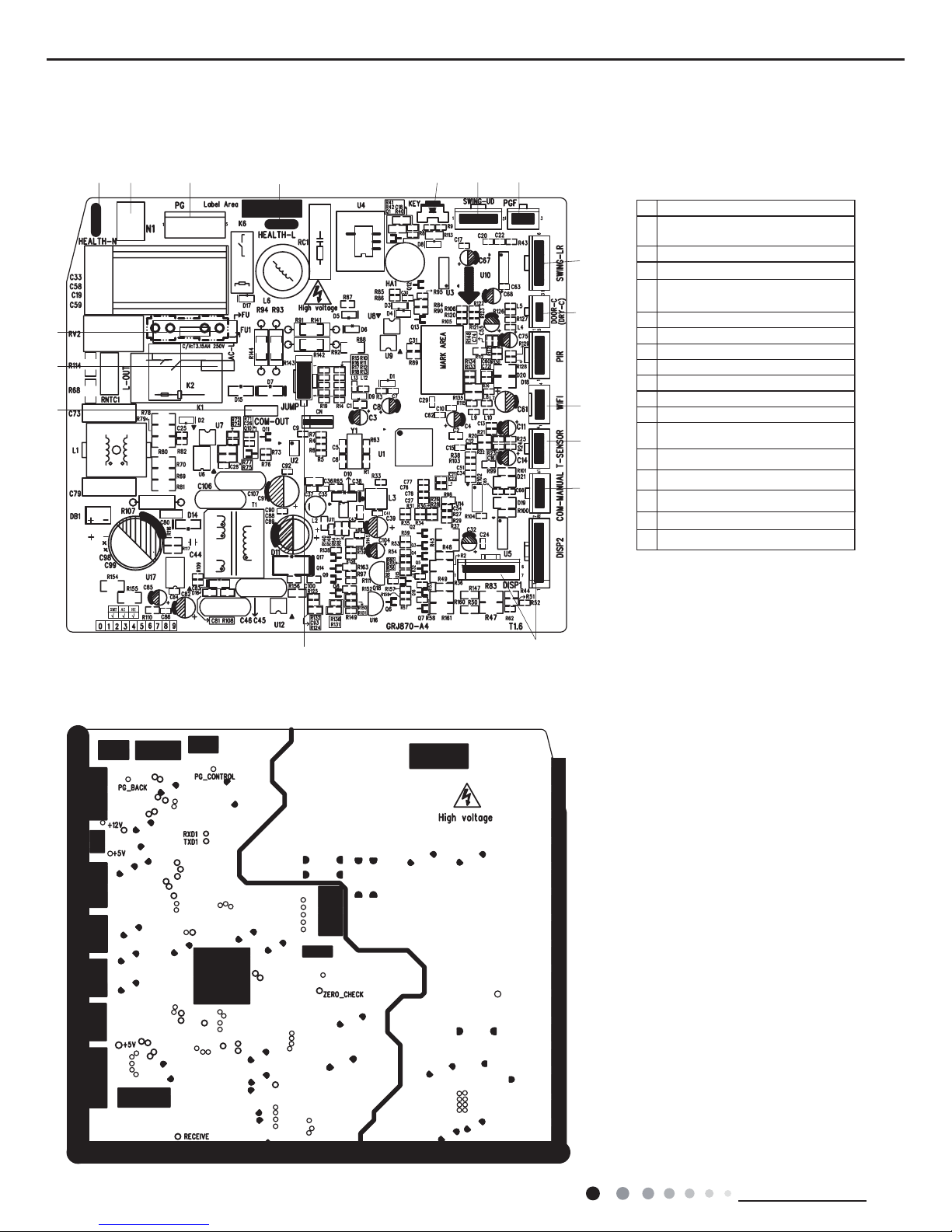
5.2 PCB Printed Diagram
Indoor Unit
No Name
1
Interface of communication wire for
indoor unit and outdoor unit
23Interface of live wire
Fuse
Interface of health function neutral
wire
4
Interface of neutral wire
5
Interface of fan
6
Interface of health function live wire
7
8
Auto button
Interface of WIFI
9 Up&down swing interface
Interface of PG feedback10
11
12
Needle stand for tube temperature
sensor
13 Display interface
14 Jump
15
15
16
11
12
17
14
13
45
6
89
10
● Top view
● Bottom view
1
2
3
7
Interface of left&right swing
16
Terminal of gate control function
17 Wired controller terminal
23
Technical Information
Service Manual
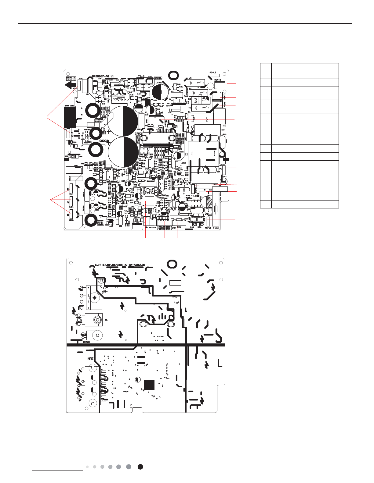
No. Name
1
Interface of compressor wire
2
Interface of reactor
3
Terminal of chassis electric
heater
4
Terminal of compressor
electric heater
5
Terminal of 4-way valve
6
Interface of outdoor fan
7
Interface of earthing wire
8
Communication interface
9
Interface of netural wire
10
Interface of live wire
11
Terminal of electronic
expansion valve
12
Interface of temperature
sensor
13
Overload interface of
compressor
14
Main chip
1
2
3
4
5
6
7
8
9
10
11121314
Outdoor Unit
● Top view
● Bottom view
09/12K
24
Technical Information
Service Manual
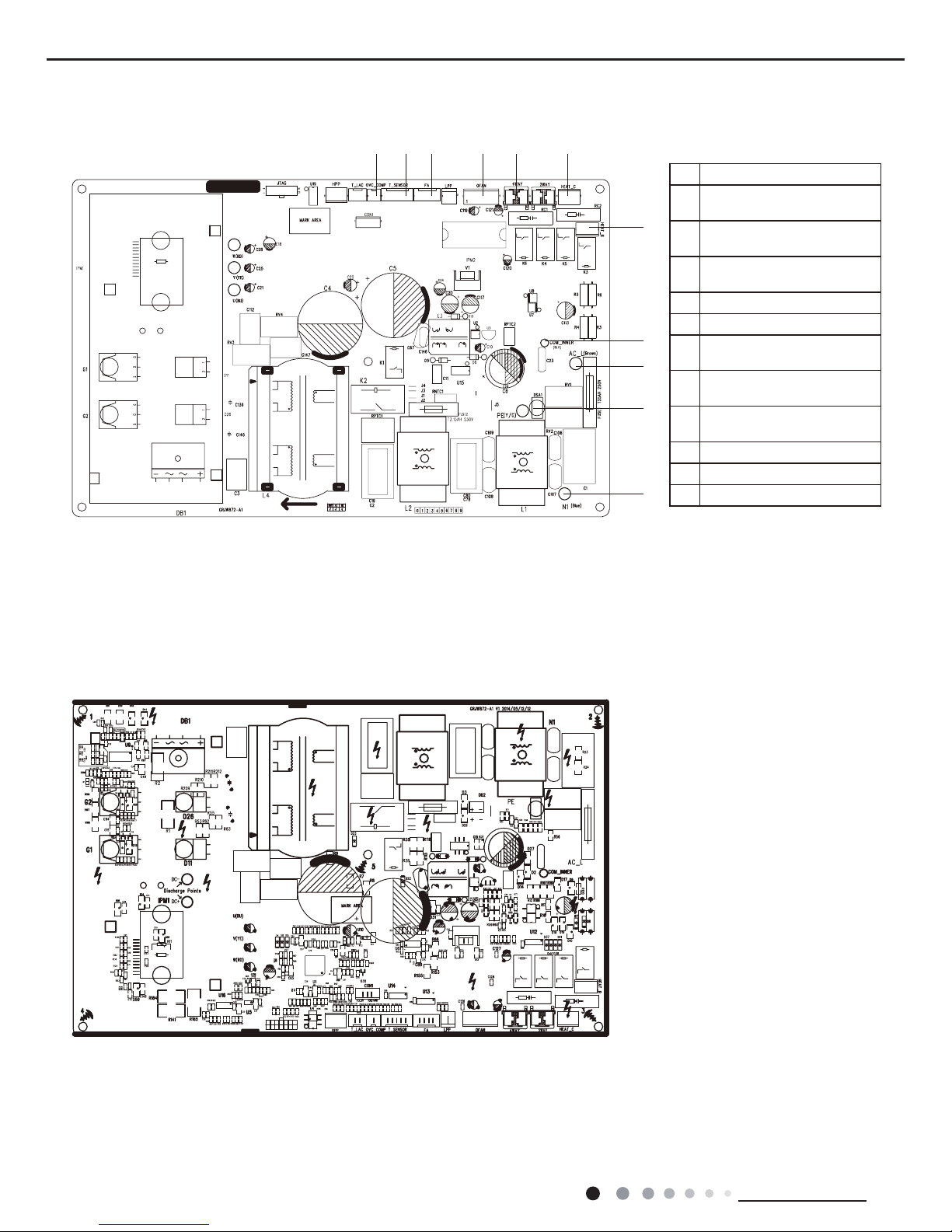
18K
● Top view
● Bottom view
No.Name
1
Terminal of compressor
overload protection
2
Terminal of temperature
sensor
3
Terminal of electronic
expansion valve
4
Terminal of outdoor fan
5
Terminal of 4-way valve
6
Terminal of compressor
electric heating
7
Terminal of chassis electric
heating
8
Terminal of indoor unit and
outdoor unit communication
9
Power supply live wire
10
Earthing wire
11
Power supply neutral wire
123456
7
8
9
10
11

25
Technical Information
Service Manual
1
234
5
6
7
8
9
1 Terminal of compressor
2
Terminal of electronic
expansion valve
3
Terminal of temperature
sensor
4
Overload terminal of
compressor
5 Terminal of outdoor fan
6 Live wire
7 Communication wire
8 Earthing wire
9 Neutral wire
● Top view
● Bottom view
24K
26
Technical Information
Service Manual
6. Function and Control
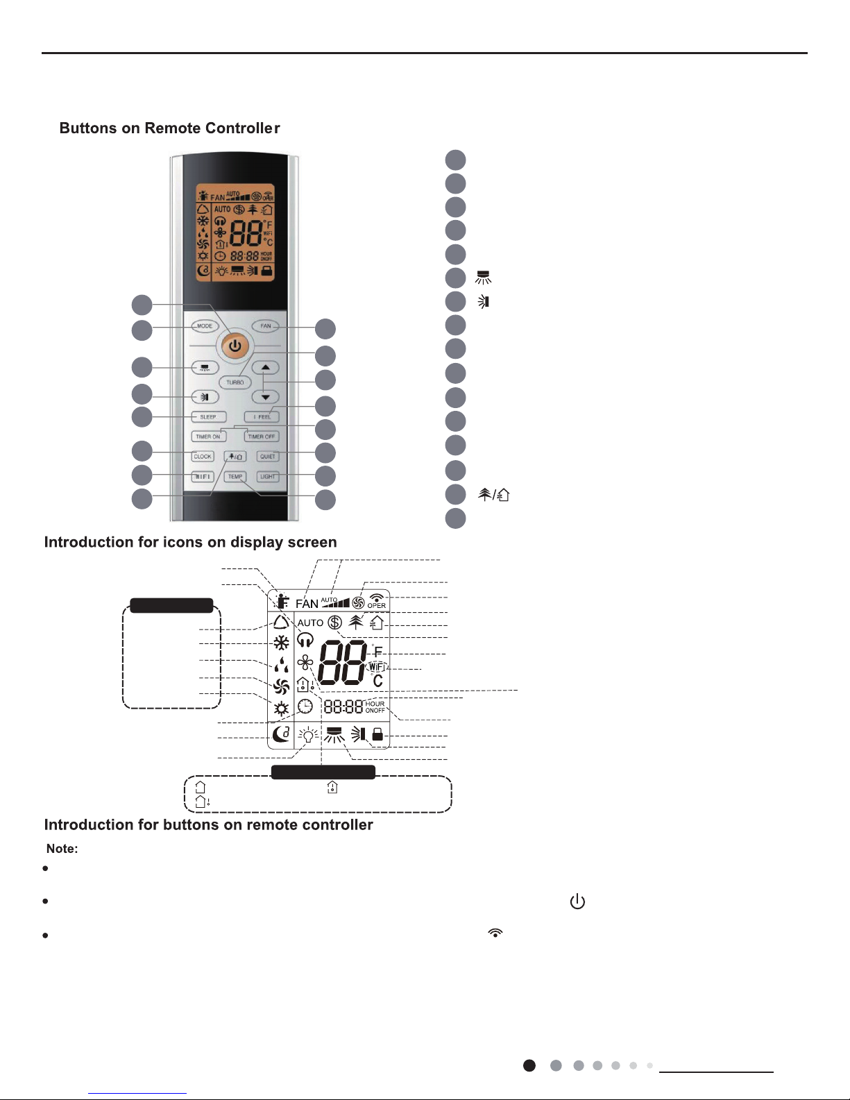
6.1 Remote Controller Introduction
Set fan speed
Send signal
Turbo mode
8ć heating function
Set temperature
Set time
X-FAN function
TIMER ON/TIMER OFF
Child lock
Up & down swing
Left & right swing
Light
Temp. display type
:Set temp.
:Outdoor ambient temp.
:Indoor ambient temp.
Sleep mode
Clock
Heat mode
Fan mode
Dry mode
Cool mode
Auto mode
Operation mode
I feel
Healthy mode
Scavenging functions
Quiet
WiFi
This is a general remote controller.Some
models have this function while some
do not. Please refer to the actual models.
{
6
3
7
9
11
13
15
12
14
16
10
8
5
4
2
1
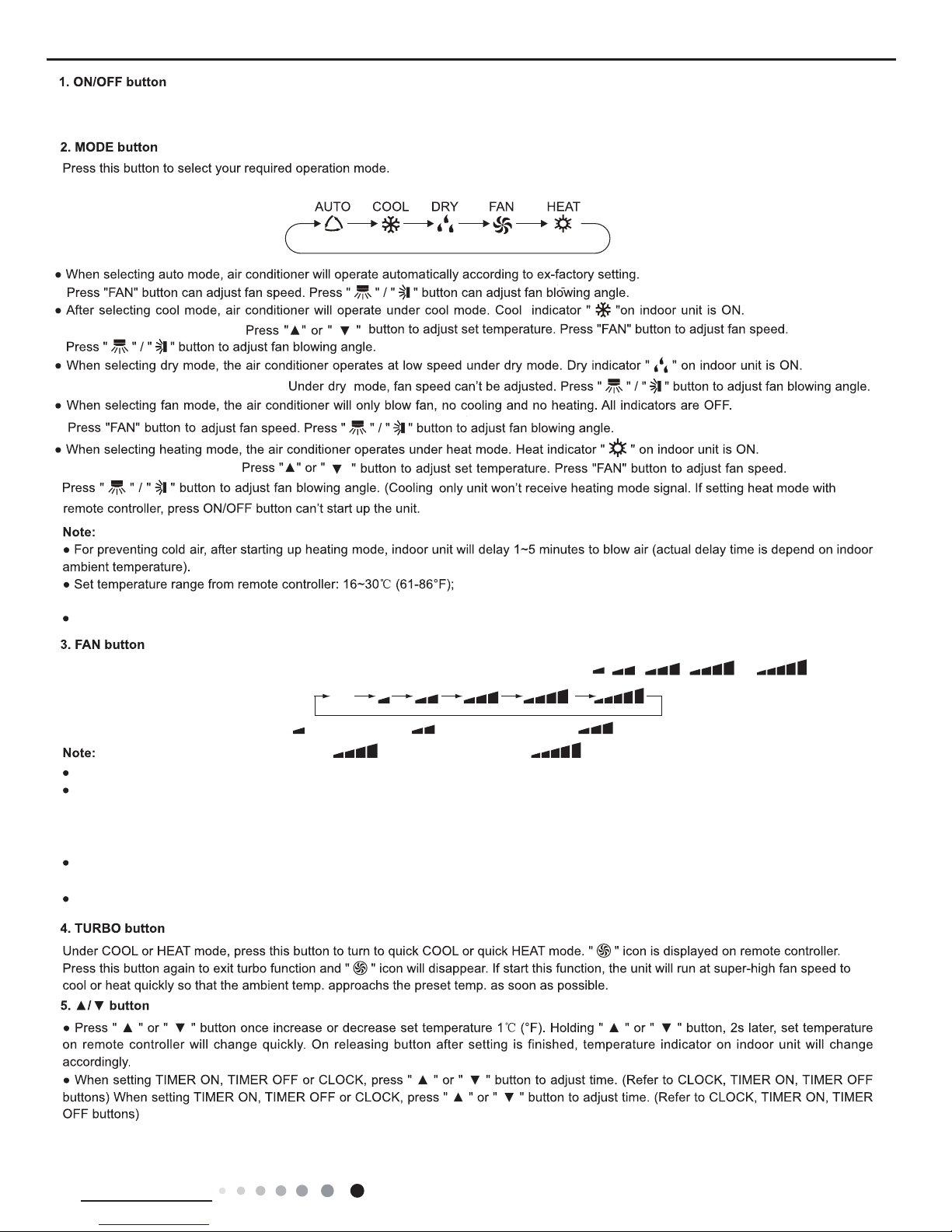
1 ON/OFF button
2 MODE button
3 FAN button
4 TURBO button
6 button
7 button
9 I FEEL button
14 LIGHT button
15 button
16 TEMP button
11 CLOCK button
12 QUIET button
13
WiFi button
10 TIMER ON / TIMER OFF button
8 SLEEP button
5 ▲/ button
▲
This is a general use remote controller, it could be used for the air conditioners with multifunction; For some function, which the
model doesn't have, if press the corresponding button on the remote controller that the unit will keep the original running status.
After putting through the power, the air conditioner will give out a sound. Operation indicator " " is ON (red indicator,the colour is
different for different models). After that, you can operate the air conditioner by using remote controller.
Under on status, pressing the button on the remote controller, the signal icon " " on the display of remote controller will blink
once and the air conditioner will give out a “di” sound, which means the signal has been sent to the air conditioner.
●As for the models with functions of WiFi or wired controller
, the indoor unit must has been controlled by standard remote controller under auto
mode first,and then the function of adjustable temperature under auto mode can be realized by
APP or the wired controller.
●This remote controller can adjust the temperature under auto mode. When matching with the unit which is without the function
of adjustable
temperature under auto mode, the set temperature under auto mode may be invalid, or the displayed set temperature on the unit
is not same as
that on the remote controller under auto mode.
27
Technical Information
Service Manual
Press this button to turn on the unit. Press this button again to turn off the unit.
It’s Low fan speed under Dry mode.
X-FAN function Hold fan speed button for 2s in COOL or DRY mode, the icon “ ” is displayed and the indoor fan will continue operation for
a few minutes in order to dry the indoor unit even though you have turned off the unit. After energization, X-FAN OFF is defaulted. X-FA N
is not available in AUTO, FAN or HEAT mode.
This function indicates that moisture on evaporator of indoor unit will be blowed after the unit is stopped to avoid mould.
Having set X-FAN function on: After turning off the unit by pressing ON/OFF button indoor fan will continue running for a few minutes. at
low speed. In this period, Hold fan speed button for 2s to stop indoor fan directly.
Having set X-FAN function off: After turning off the unit by pressing ON/OFF button, the complete unit will be off directly.
(This indicator is not
(This indicator
Operation indicator is ON.
available for some models).
(This indicator is not
available for some models).
is not available for some models).
Fan speed: auto, low speed, low-medium speed,medium speed,
medium-high speed,high speed.
Under auto mode, temperature can be displayed;Under auto mode,set temperature can be adjusted.
This button is used for setting Fan Speed in the sequence that goes from AUTO,
,
to
,,
,
then back to Auto.
Low-Medium speed
Medium-High speed
Medium speed
High speed
Auto
Low speed
 Loading...