

Gree GWH09AB-A3DNA1B, GWH12AB-A3DNA1B Service Manual

GREE ELECTRIC APPLIANCES,INC.OF ZHUHAI
Service Manual
MODEL:GWH09AB-A3DNA1B
GWH12AB-A3DNA1B
(Refrigerant R410A)

Table of Contents
Summary and Features
.................................................................................1
Part 1 Safety Precautions
..........................................................................................2
Part 2 Specifications
.....................................................................................................3
Part 3 Construction Views
........................................................................................5
3.1 Indoor Unit ........................................................................................................
.....5
3.2 Outdoor Unit ..........................................................................................................5
Part 4 Refrigerant System Diagram
.....................................................................6
5.1 Electrical Data........................................................................................................7
5.2 Electrical Wiring......................................................................................................7
Part 5 Schematic Diagram
........................................................................................7
6.1 Remote Control Operations..................................................................................11
6.2 Changing Batteries and Notices ..........................................................................13
6.3 Description of Each Control Operation.................................................................14
Part 6 Function and Control
...................................................................................11
Part 7 Installation Manual
........................................................................................19
7.2 Installation Drawing..............................................................................................21
7.3 Install Indoor Unit.................................................................................................22
7.4 Install Outdoor Unit ..............................................................................................24
7.5 Check After Installation and Operation Test.........................................................25
5.3 Printed Circuit Board...........................................................................................
....9
7.1 Notices for Installation...........................................................................................19

Table of Contents
Part 8 Exploded Views and Parts List
..............................................................26
Part 9 Troubleshooting
...............................................................................................32
9.1
Malfunction Analysis
.............................................................................................32
9.2
Flashing LED of Indoor/Outdoor Unit and Primary Judgement
............................36
9.3
How to Check Simply the Main Part
.....................................................................39
8.1 Indoor Unit............................................................................................................26
8.2 Outdoor Unit.........................................................................................................28
Part10 Removal Procedure
.......................................................................................48
10.1
Removal Procedure of Indoor Unit
.....................................................................48
10.2
Removal Procedure of Outdoor Unit
...................................................................51
1
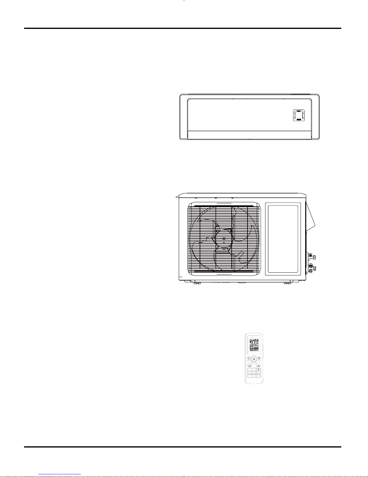
Summary and Features
Indoor Unit
GWH09AB-A3DNA1B/I
GWH12AB-A3DNA1B/I
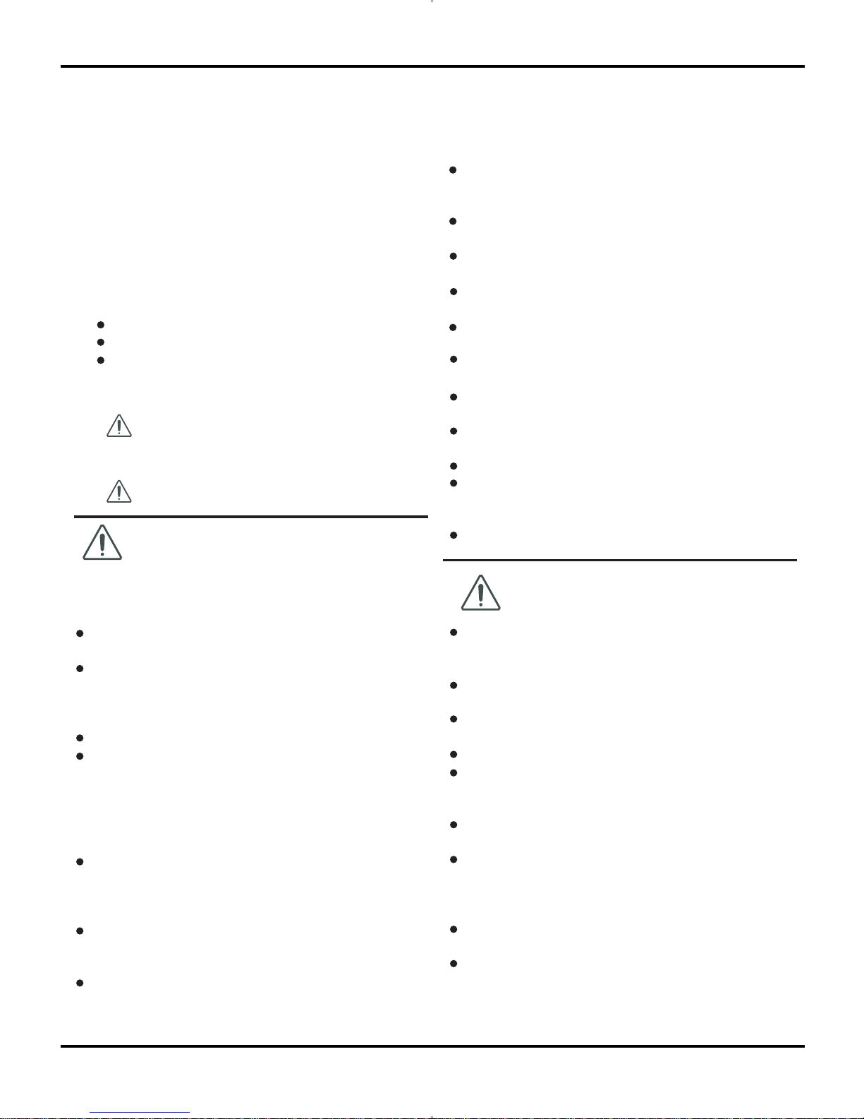
Outdoor Unit
GWH09AB-A3DNA1B/O
GWH12AB-A3DNA1B/O
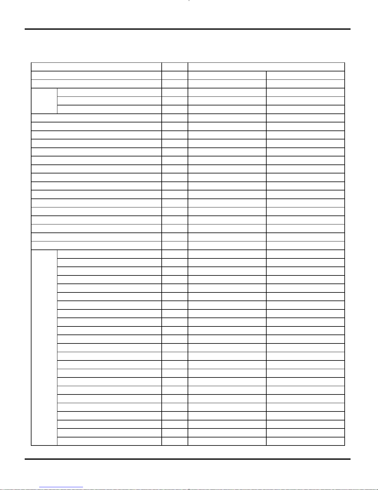
Remote control window
YT1FF
Summary and Features
FAN
MODE
IFEEL
CLOCK
TIMER
ON
X-FAN TEMP
TIMER
OFF
TURBO SLEEP LIGHT
2
Safety Precautions
1.Safety Precautions
Important!
This air conditioning system meets strict safety and
operating standards. As the installer or service person,
it is an important part of your job to install or service the
system so it operates safely and efficiently.
Follow each installation or repair step exactly as shown.
Observe all local, state, and national electrical codes.
Pay close attention to all warning and caution notices
given in this manual.
To prevent injury to the user or other people and
property damage, the following instructions must
be followed.
About the pictures:
Erroneous handing gives a high possi-
bility to induce serious results such as
death or heavy injury.
Erroneous handing may induce serious
injury depending on the situation.
Do not supply power to the unit until all wiring and tubing
are completed or reconnected and checked.
Highly dangerous electrical voltages are used in this
system. Carefully refer to the wiring diagram and these
instructions when wiring. Improper connections and inad-
equate grounding can cause accidental injury or death.
Ground the unit following local electrical codes.
Connect all wiring tightly. Loose wiring may cause over-
heating at connection points and a possible fire hazard.
All electric work must be performed by licensed technician, ac-
cording to local regulations and the instructions given in this
manual.
There is risk of fire, electric shock, explosion, or injury.
Ask your dealer or specialized subcontractor for installation or
repair work.
Make sure the ceiling/wall is strong enough to hold the
unit’s weight. The outdoor unit should be installed in a
location where air and noise emitted by the unit will not
disturb the neighbors.
Properly insulate any tubing run inside a room to prevent
"sweating" that can cause dripping and water damage to
walls and floors.
The outdoor unit must be installed on stable, level surface,
in a place where there is no accumulation of snow, leaves
or rubbish.
The unit should be installed according to the instructions
in order to minimize the risk of damage from earthquakes,
typhoons or strong winds.
When the refrigerant touches the fire etc., it was decomposed
and a poisonous gas is generated.
Use only the specified refrigerant to charge the refrigerant
circuit.
Do not mix it with any other refrigerant and do not allow air to
remain in the circuit.
Air enclosed in the circuit can cause high pressure resulting
in a rupture and other hazards.
After completing installation work, make sure that refriger-
ant gas has not leaked.
The limit density is made not to be exceeded even if the refrig-
erant leaks by any chance.
Turn the power off at the main power box (mains) before open-
ing the unit to check or repair electrical parts and wiring.
Keep your fingers and clothing away from any moving parts.
Clean up the site after you finish, remembering to check that
no metal scraps or bits of wiring have been left inside the unit
being serviced.
The unit must be properly earth connected.
Caution
Warning
Warning
Caution
Never install on the place where a combustible gas might
leak. The gas may ignite or explode when the gas leaks and
collects in surround of the unit.
When the unit is installed at telecommunication centers or
hospitals, take a proper provision against noise.
When installing at a watery place, provide an electric leak
breaker.
Do not wash the unit with water.
Be very careful about unit transportation. The unit should not
be carried by only one person if it is more than 20kg. It occasion-
ally causes the damage of the unit and health to be impaired.
Do not touch the heat exchanger fins with your hands.
Doing so may cut your hands.
Do not touch the compressor or refrigerant piping without
wearing glove on your hands. Touching directly such part can
cause a burn or frostbite as it becomes high or low temperature
according to the refrigerant state.
Do not operate the air conditioner without the air filter set
place. Dust may accumulate, and cause a failure.
At emergency (if you smell something burning), stop opera-
tion and turn the power source switch off.
Please Read Before Srarting
3
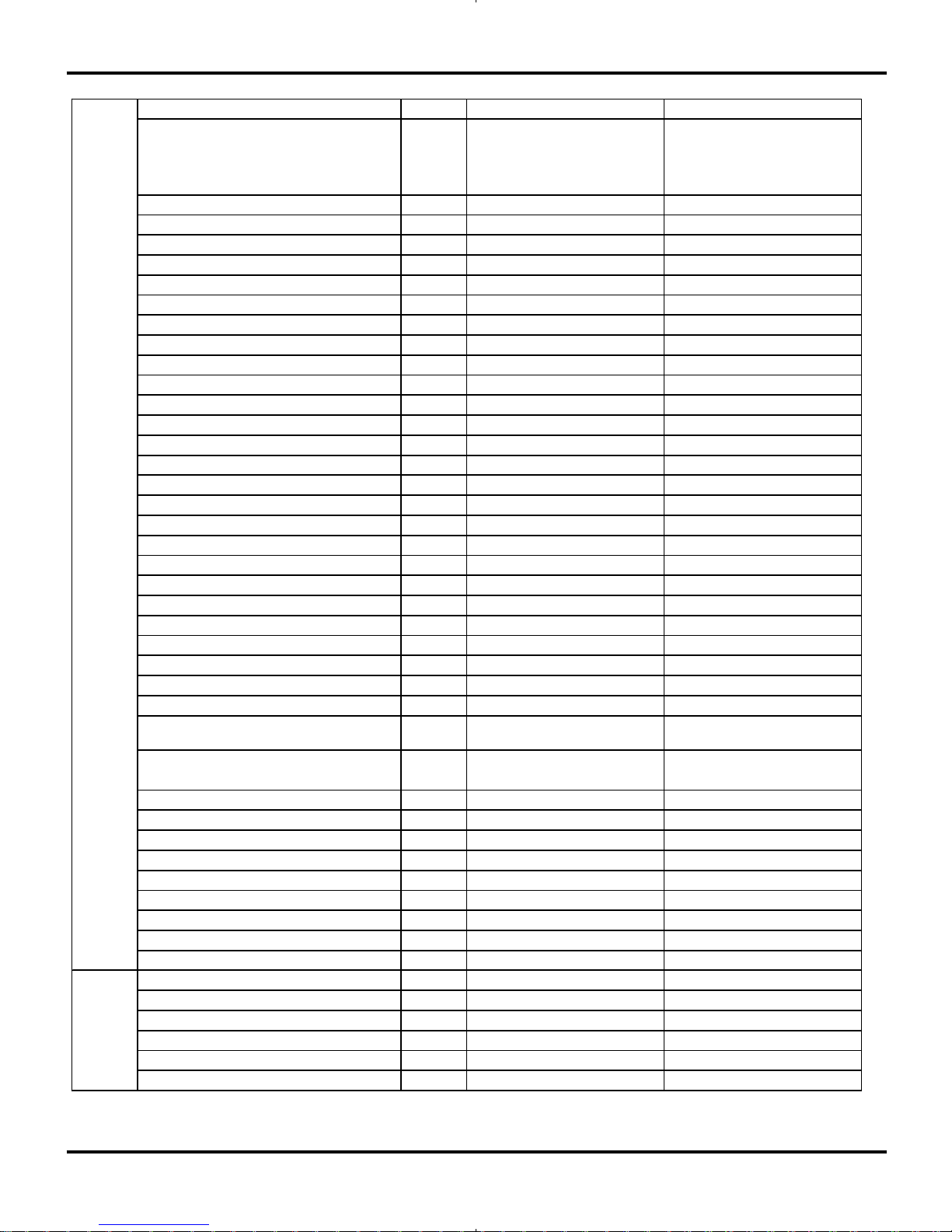
2.Specifications
Specifications
Unit
GWH09AB-A3DNA1B GWH12AB-A3DNA1B
CB11500550 CB11500570
Rated Voltage V
~
115 115
Rated Frequency Hz 60 60
Phases 1 1
Outdoor Outdoor
Btu/h 9000(4000~11950) 12000(4500~13000)
Btu/h 9500(3412~12500) 13000(3200~14000)
W 620(166~1180) 1000(160~1180)
W 680(200~1230) 1140(400~1250)
A5.3 8.70
A 6 10.00
W 1100 1300
A10 12
m
3
/h
520/430/370/290/- 560/490/430/350/-
L/h 1.2 1.4
W/W 4.33 3.52
W/W 4.04 3.34
W/W 23 22
W/W 9 9
m
2
12-18 16-24
Model of indoor unit GWH09AB-A3DNA1B/I GWH12AB-A3DNA1B/I
Fan Type Cross-flow Cross-flow
Diameter Length(DXL) mm Φ85X668 Φ85X668
Fan Motor Cooling Speed (SH/H/M/L/SL) r/min 1400/1150/1050/900/- 1500/1150/1050/900/-
Fan Motor Heating Speed (SH/H/M/L/SL) r/min 1450/1250/1150/1050/400 1450/1250/1150/1050/400
Output of Fan Motor W 10 10
Fan Motor RLA A / /
Fan Motor Capacitor μF/ /
Input of Heater W / /
Evaporator Form Aluminum Fin-copper Tube Aluminum Fin-copper Tube
Pipe Diameter mm Φ7 Φ7
Row-fin Gap mm 2-1.5 2-1.5
Coil Length (LXDXW) mm 657X25.4X285 657X25.4X285
Swing Motor Model MP28VB MP28VB
Output of Swing Motor W 2 2
Fus e A 3.15 3.15
Sound Press ure Level (SH/H/M/L/SL) dB (A) 42/38/30/28/- 47/38/30/28/-
Sound Power Level (SH/H/M/L/SL) dB (A) 52/48/40/38/- 57/48/40/38/-
Dimension (WXHXD) mm 872X283X178 872X283X178
Dimension of Carton Box (L/W/H) mm 935X260X375 935X260X375
Dimension of Package (L/W/H) mm 938X275X378 938X275X378
Net Weight kg 12 12
Gross Weight kg 15 15
ValueParam eter
Model
Product Code
Power
Supply
Power Supply Mode
Cooling Capacity (Min~Max)
Heating Capacity (Min~Max)
Cooling Power Input (Min~Ma x)
Heating Power Input (Min~Ma x)
Cooling Power Current
Heating Power Current
Rated Input
Rated Current
Air F l ow Vol u m e( SH/ H/M/L/SL)
Dehumidifying Volume
Application Area
Indoor
Unit
EER
COP
SEER
HSPF
4
The above data is subject to change without notice. Please refer to the nameplate of the unit.
Specifications
Model of Outdoor Unit GWH09AB-A3DNA1B/O GWH12AB-A3DNA1B/O
Compressor Manufacturer/Trademark
CHINA
RESOURCES(SHENYANG)
SANYO COMPRESSOR CO.
LTD ./S ANYO
CHINA
RESOURCES(SHENYANG)
SANYO COMPRESSOR CO.
LTD ./S ANYO
Compressor Model C-6RZ110H1A C-6RZ110H1A
Compressor Oil FV50S FV50S
Compressor Type Rotary Rotary
L.R.A. A 33.00 33
Compressor RLA A 4.59 4.59
Compressor Power Input W 800 800
Overload Protector Int11l-3979 Int11l-3979
Throttling Method Electron expansion valve Electron expansion valve
Operation temp ºC 16~30 16~30
Ambient temp (cooling) ºC 18~43 18~43
Ambient temp (heating) ºC -7~24 -7~24
Condenser Form Aluminum Fin-copper Tube Aluminum Fin-copper Tube
Pipe Diameter mm Φ9.52 Φ9.52
Rows-fin Gap mm 2-1.4 2-1.4
Coil Length (LXDXW) mm 747X44X508 747X44X559
Fan Motor Speed rpm 830 830
Output of Fan Motor W 30 30
Fan Motor RLA A / /
Fan Motor Capacitor μF/ /
Air Flow Volume of Outdoor Unit
m
3
/h
1800 2000
Fan Type Axial-flow Axial-flow
Fan Diameter mm Φ400 Φ400
Defrosting Method Automatic Defrosting Automatic Defrosting
Clim ate Type T1 T1
Is ol ati on I I
Mois ture Protection IP24 IP24
Permissible Excessive Operating
Pressure for the Discharge Side
MPa 3 .8 3.8
Permissible Excessive Operating
Pressure for the Suction Side
MPa 1 .2 1.2
Sound Press ure Level (H/M/L) dB (A) 52/-/- 55/-/-
Sound Power Level (H/M/L) dB (A) 62/-/- 65/-/-
Dimension (WXHXD) mm 848X540X320 848X590X320
Dimension of Carton Box (L/W/H) mm 878X360X580 878X360X630
Dimension of Package (L/W/H) mm 881X363X595 881X363X645
Net Weight kg 40 41
Gross Weight kg 44 45
Refrigerant R410A R410A
Refrigerant Charge kg 1.35 1.35
Length m 7.5 7.5
Gas Additional Charge g/m 20 20
Outer Diameter Liquid Pipe mm Φ6 Φ6
Outer Diameter Gas Pipe mm Φ9.52 Φ12
Max Distance Height m 10 10
Max Distance Length m 15 20
Outdoor
Unit
Connecti
on Pipe
5
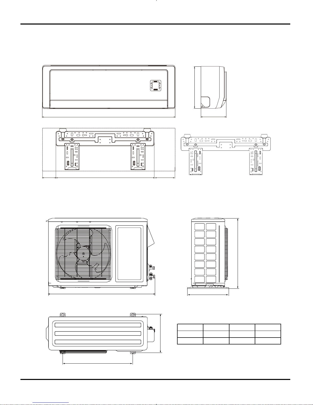
3. Construction Views
3.1 Indoor Unit
Constrction Views
Unit:mm
101
872
178
605 166
283
12K Unit:
3.2 Outdoor Unit
D
540
286
H
W
Model W H D
09K 848 540 320
12K 848 590 320
6
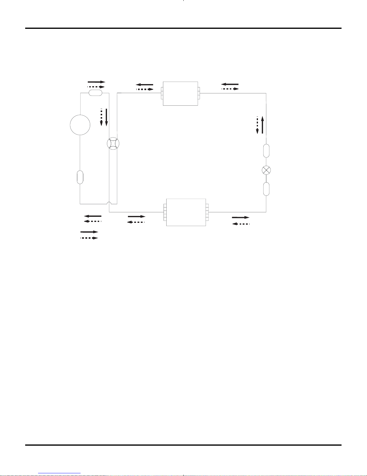
4. Refrigerant System Diagram
Refrigerant pipe diameter
09K Unit
Liquid : 1/4" (6 mm)
Gas : 3/8" (9.52 mm)
12K Unit
Liquid : 1/4" (6 mm)
Gas : 1/2" (12 mm)
Refrigerant System Diagram
Strainer
Strainer
Muffler
4-Way valve
Expansion valve
Heat exchanger
( INDOOR )
Heat exchanger
( OUTDOOR )
rotalumucca-buS
rosserpmoC
Cooling
Heating
7
5. Schematic Diagram
5.1 Electrical Data
5.2 Electrical wiring
Outdoor Unit
Symbol Color symbol Symbol Color symbol
WH
WHITE
BN
BROWN
YE
YELL OW
BU
BLUE
RD
RED
BK
BLACK
YEGN
YELLOW GREEN PROTECTIVE EARTH
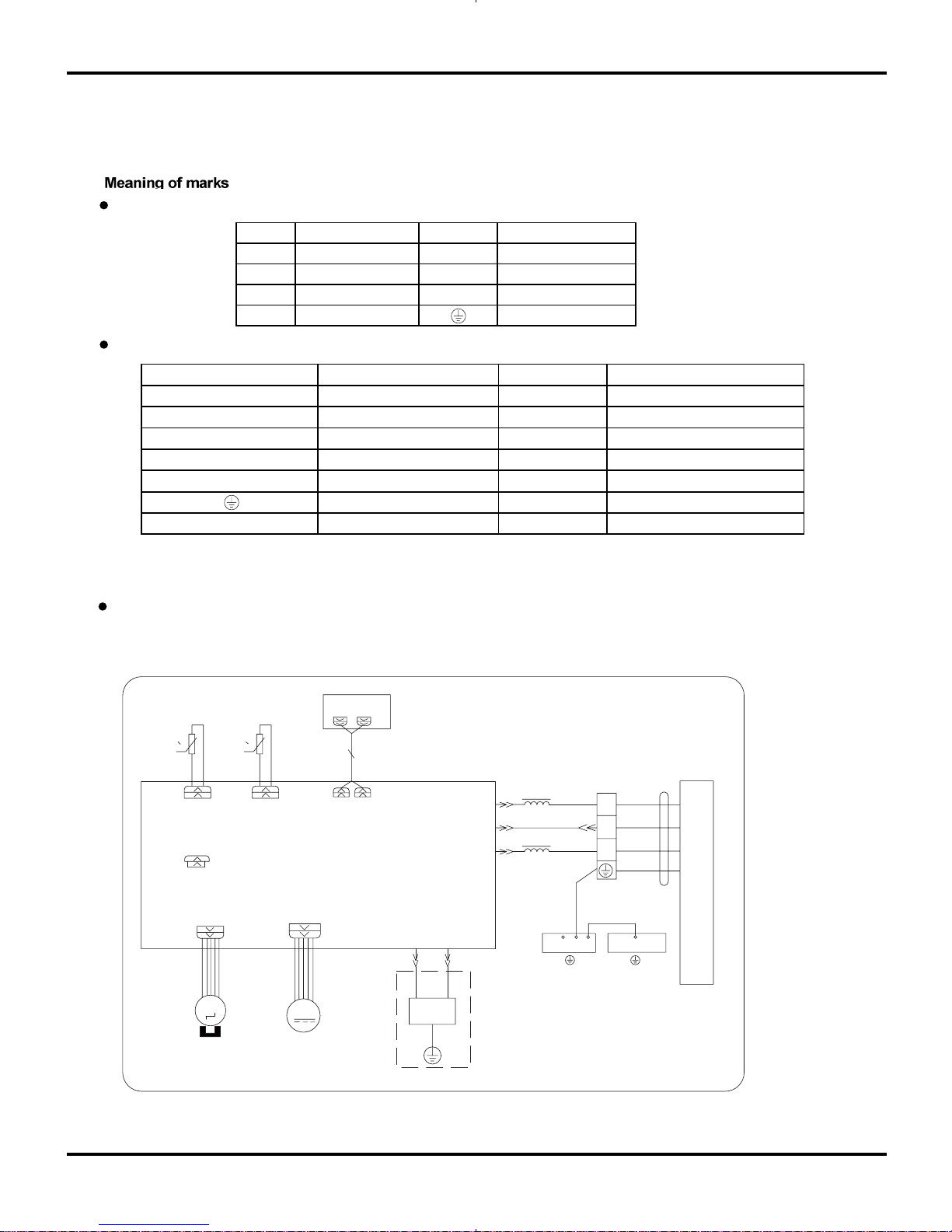
Indoor Unit
Indoor Unit
Schematic Diagram
Symbol Parts name Symbo l Col o r symbo l
L1 L2 WH
WHITE
4YV YE
YELLOW
EKV RD
RED
L BN
SAT OVERLOAD BN BROWN
COMP
COMPRESSOR
BU
BLUE
PROTECTIVE EARTH
BK
BLACK
YEGN
YELLOW GREEN
AP1 DISPLAY
EVAPORATOR
ELECTRIC BOX
W5
BK
N1
W2 YEGN
W1YEGN
COM-INNER
3
2
OUTDOOR UNIT
N(1)
AP2
L
W3
BN
W4
BU
XT1
G
HEALTH-LHEALTH-N
YEGN
BURD
GG
FAN MOTOR
STEP MOTOR
ROOM TUBE
DISP3 DISP4
00
TEM.SENSOR
TUBE
ROOM
TEM.SENSOR
RT1 RT2
JUMP
L1
L1
COOL PLASMA
GENERATOR
M
M
SWING-UD CN1
NEUTRAL WIRE, LIVE WIRE
4-WAY VALVE
ELETRIC EXPANSION VALVE
REACTOR
8
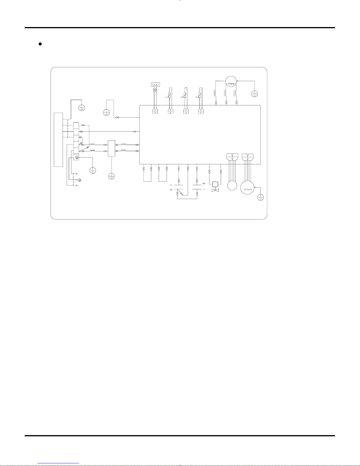
Outdoor Unit
Schematic Diagram
4YV
RT5
0
0
RT4
0
RT3
OUTROOM
EXHAUST
OUTTUBE
OFAN
E
OVERHEAT
R
E
C
S
U
V
W
CT1,2
AP1
W3YEGN
W10 RD
COMP
W8 YEGN
FAN MOTOR
W5 BU
W6 YE
W7 BK
AC-N1
AC-L1
4V
AC-N2
COMU
EKV
CN1
TEM.SENSOR
OUTROOM
EXHUAST
TEM.SENSOR
TEM.SENSOR
TUBE
W2 BU
W1 BN
W4 BK
G
G
I
N
D
O
O
R
U
N
I
T
W13 YEGN
POWER
N
L
L
N
N(1)
3
2
L2L2L2
L1
L1
G
G
G
W15 BU
W14 BN
W16 WH
W17 RD
G
L4
L4
W23 OGW20 BU
W22 WH
W21 BN
AC-L2 AC-L4AC-N5AC-N3 AC-N4 AC-L2AC-L3
W19 BU W24 RD
W18 YEGN
COMP
M
XT2
3
4
E
2
1
FILTER
C4
C3
2
1
2
1
These circuit diagrams are subject to change without notice, please refer to the one supplied with the unit.
9
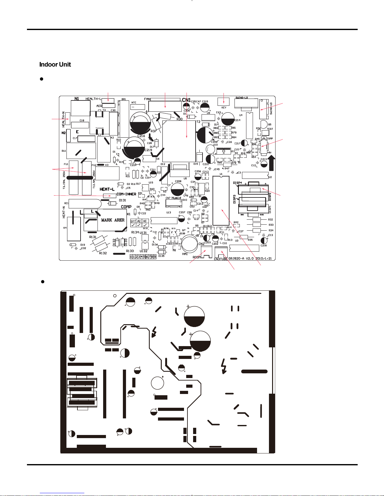
5.3 Printed Circuit Board
TOP VIEW
BOTTOM VIEW
Schematic Diagram
interface of health function live wire
indoor fan interface
high frequency
transformer auto button
indoor ambient temperature sensor
indoor tube temperature sensor
main chip
communication interface
fuse
interface of health function nuetral wire
up & down swing jumper cap
display interface
10
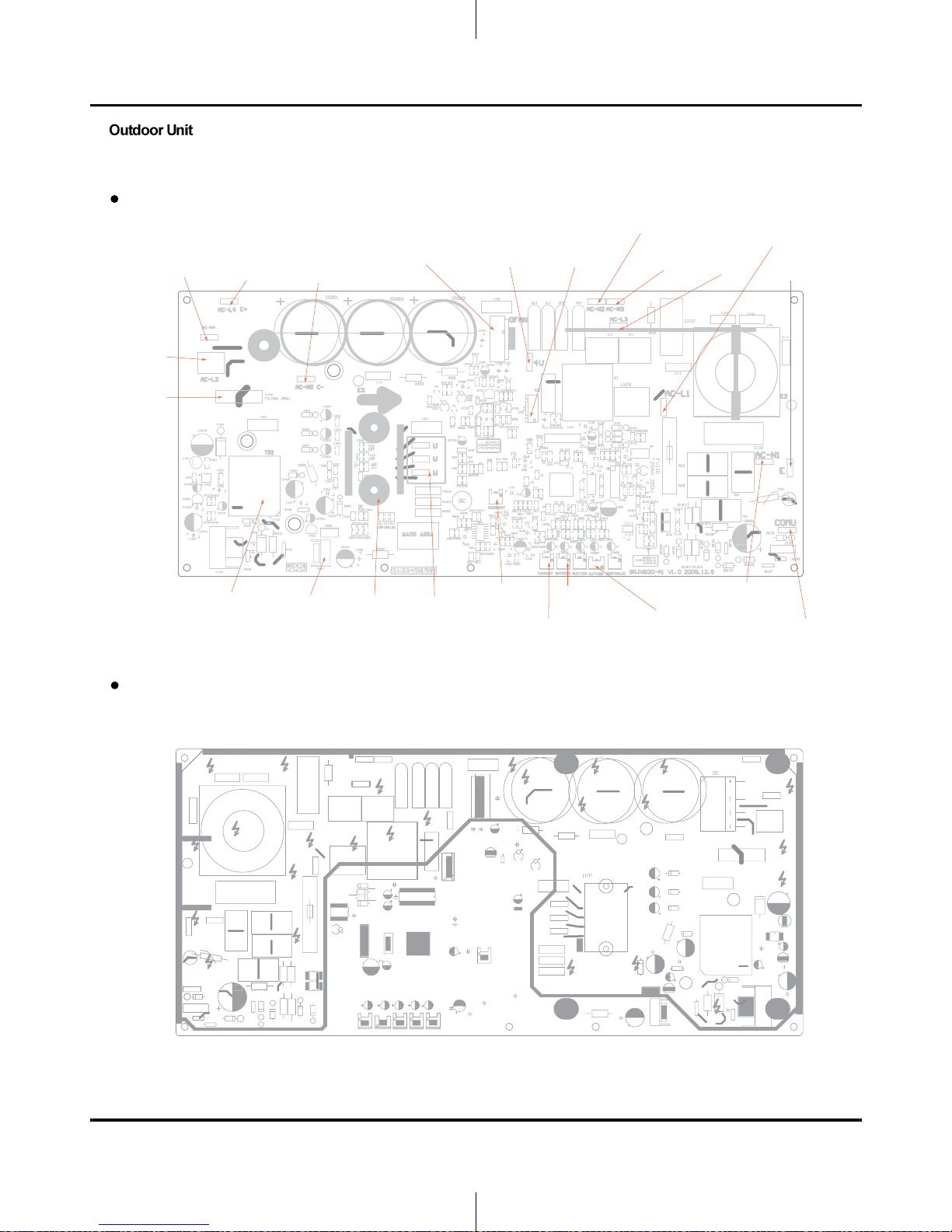
TOP VIEW
BOTTOM VIEW
Models GWH09AB-A3DNA1B/O , GWH12AB-A3DNA1B/O
Schematic Diagram
jumper
neutral wire
big capacitor
positive pole
(brown wire)
big capacitor
negative pole
(blue wire)
fan termina
l
4-way
valve terminal
electri
c
expansion
valve
jumper
neutral wire
jumper
liv
e wire terminal
live wire
earthing wire terminal
4-way valve
neutral wire
terminal
jumper live wire,
connection
terminal
of big capacitor positive
pole and negative
pole(orange
wire)
power switch fus
e
high frequenc
y
transformer
regulator
7805
IPM modula
r
compressor
3-ph
ase terminals
U phase is blue wir
e
V phase is yellow wir
e
W phase is red wire
overload temperature senso
r
outdoor
ambient
temperature
sensor
outdoor
tube
temperature
sensor
temperature
sensor
compressor discharg
e
neutral wire termina
l
communication
wire
terminal connected
to
indoor black
communication
wire
11
6. Function and Control
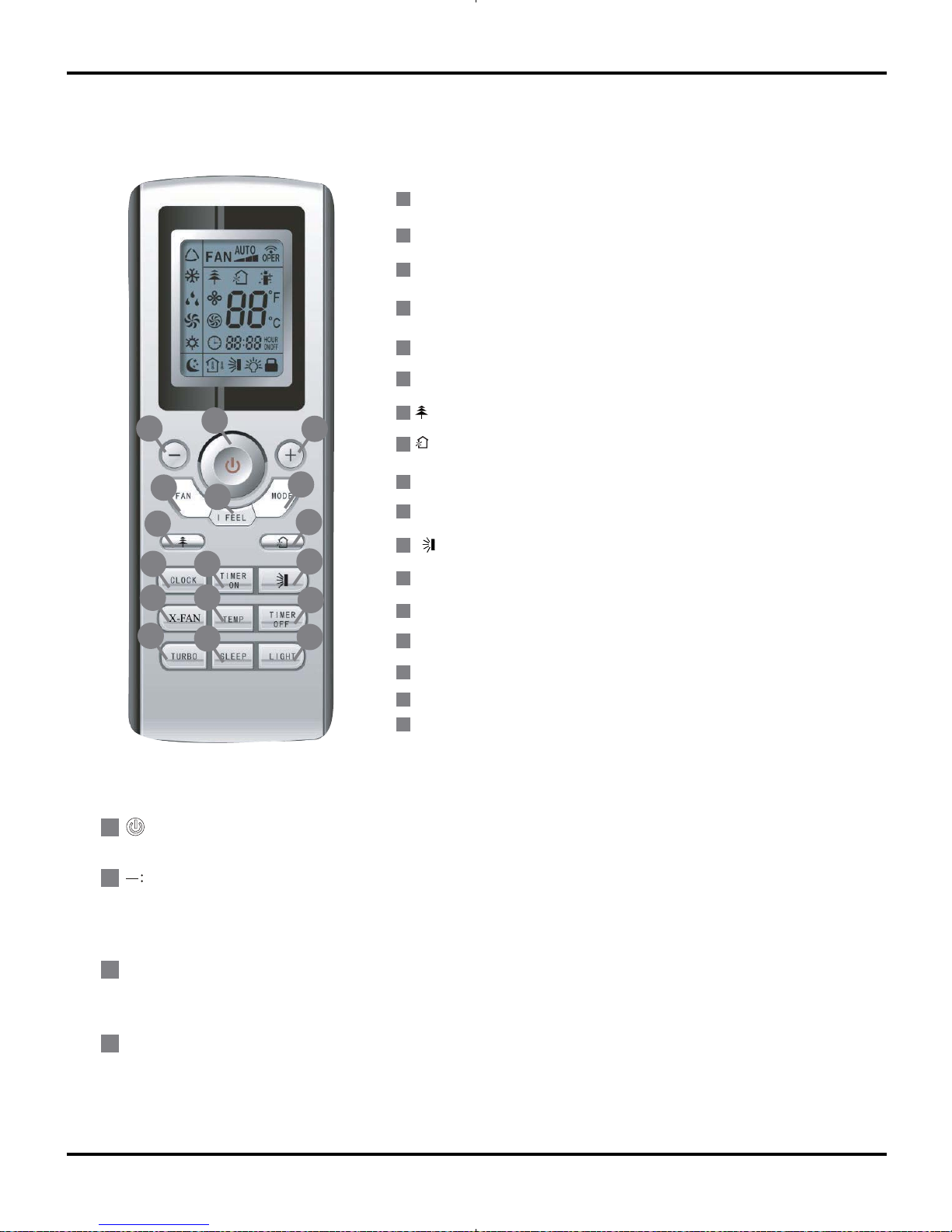
6.1 Remote Control Operations
Function and Control
Timer ON Button
TIMER OFF Button
Clock Button
X-FAN Button
Temperature Displaye Button
TURBO Button
Sleep Mode Button
Light Mode Button
ON/OFF Button
1
7
6
I FEEL Button
MODE Button
5
3
Setpoint Temperature DOWN Button
2
FAN Speed Button
4
11
10
14
9
12
13
15
16
17
8
3
14
9
10
13
16
12
5
4
15
11
8
17
7
2
1
6
+
:
FAN :
1
3
2
4
Press this button, the unit will be turned on, press it once more, the unit will be turned off.
For presetting temperature decreased. Press this button, can set up the temperature,when unit is on . Continuously
press and hold this button for more than 2 seconds,the corresponding contents will be changed rapidly,but in AUTO
mode, set temperature is not adjustable.
.
For presetting temperature increasing. Press this button, the temperature can be set up, continuously press this button
and hold for two seconds, the relative contents can quickly change, but in AUTO mode, set temperature is not adjustable.
Setpoint Temperature UP Button
HEALTH function Button
AIR function Button
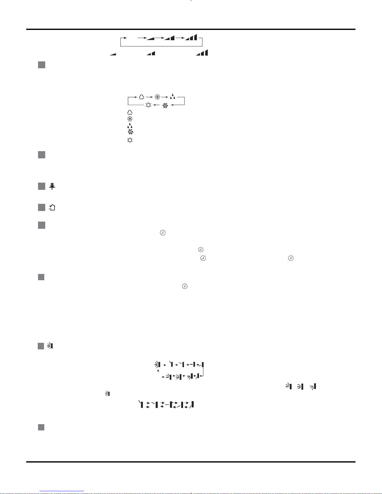
Press this button, Auto, Low, Middle, High speed can be circularly selected. After powered on, Auto fan speed is default.
Under Dehumidify mode, Low fan speed only can be set up.
(
X-FAN is the alternative expression of
BLOW for the purpose of understanding.)
12
Function and Control
CLOCK
:
9
8
7
I FEEL :
5
MODE
:
6
Press this button, I FEEL On and I FEEL Off can be selected. When turn on I FEEL function.
The unit will adjust temperature automatically according to the sensed temperature.
TIMER ON
:
11
10
X-FAN :
12
OFF
This is an universal use remote controller. If remote controller sends the following three kinds of status , or , the swing
status of mainunit will be which indicates the guide louver swings upand down between that all five positions:
:
Press this button, Auto, Cool,Dry, Fan, Heat mode can be selected circularly. Auto mode is default while power on. Under Auto
mode, the temperature will not be displayed; In this mode, the unit will automatically select the suitable operation mode in accordance with the room temperature to make the room more comfortable for you.
AUTO
COOL
DRY
FAN
Note:Only for models with heating function.
HEAT
Pressthisbutton to setHEALTHfunction ON or OFF. After the unit is turned on, it defaults to HEALTH function ON.
Press thisbutton to select AIR function ON or OFF.
Press this button, the clock can be set up,signal blink and display.Within 5 seconds, the value can be adjusted by pressing
+ or - button, if continuously press this button for 2 seconds above,in every 0.5 seconds, the value on ten place of Minute will
be increased 1. During blinking, repress the Clock button, signal will be constantly displayed and it denotes the setting succ-
eeded. After powered on, 12:00 is defaulted to display and signal will be displayed. If there is signal be displayed that
denotes the current time value is Clock value, otherwise is Timer value.
Timer On setting: Signal “ON” will blink and display, signal will conceal, the numerical section will become the timer on setting
status. During 5 seconds blink,by pressing + or - button to adjust the time value of numerical section, every press of that button, the value will be increased or decreased 1 minute. Hold pressing + or -button, 2 seconds later, it quickly change, the way
of change is:During the initial 2.5 seconds, ten numbers change in the one place of minute, thenthe one place is constant, ten
numbers change in the tens place of minute at 2.5 seconds speed and carry. During 5s blink, press the Timer button, the timer
setting succeeds. The Timer On has been set up, repress the timer On button, the Timer On will be canceled. Before setting the
Timer, please adjust the Clock to the current actual time.
Press this button, to set up swing angle, which circularly changes as below:
When the guide louver start to swing up and down, if turn off the Swing, the air guide louver will stop at current position.
Pressing X -FAN button in COOL or DRY mode,the icon is displayed and the indoor fan will continue operation for 10 minutes in
order to dry the indoor unit even you have turned off the unit.After energization, X-FAN OFF is defaulted. X-FAN is not available
in AUTO,FAN or HEAT mode.
Auto
Low speed
Medium speed
High speed
(The function is not for the models mentioned in the manual.)
(The function is not for the models mentioned in the manual.)
13
Function and Control
ƾ
●
●
●
●
●
When replacing the batteries, do not use used or different types of batteries,otheerwise,
If the remote controller will not be used for a long time, please
it may cause malfunction.
remove batteries
to prevent batteries from leaking.
The operation should be performed in its receiving range.
It should be kept 1m away from the TV set or stereo sound sets.
If the remote controller does not operate normally, please take the
batteries out
and replace them after 30 seconds. If it still can't operate properly, replace the batteries.
Notes:
Sketch map for
replacing batteries
18
19
SLEEP:
LIGHT:
16
17
Press this button, Sleep On and Sleep Off can be selected. After Sleep function set up, the unit will automatically select
the suitable operation mode to maintain the most comfortable temperature for you. This function is available in COOL ,
HEAT or DRY mode
TURBO:
15
Press this button to activate / deactivate the Turbo function which enables the unit to reach the preset temperature in
shortest time. Such as in COOL mode, the unit will blow strong cooling air at super high fan speed. In HEAT mode, the
unit will blow strong heating air at super high fan speed.
(This function is not applicable for some models)
Press this button to select LIGHT on or off in the displayer. When the LIGHT on is set,the icon will be displayed and
the indicator light in the displayer will be on. When the LIGHT off is set, the icon will be displayed and the indicator
light in thedisplayer will be off.
"+" and "–"button about lock:
Press "+ " and "-" buttons simultaneously to lock or unlock the keypad. If the remote controller is locked, is displayed .
In this case, pressing any button , blinks three times.
"MODE" and " - " buttons About switch between fahrenheit and cenrigrade:
At unit OFF, press "MODE" and " - " buttons simultaneously to switch between ℉ and ℃.
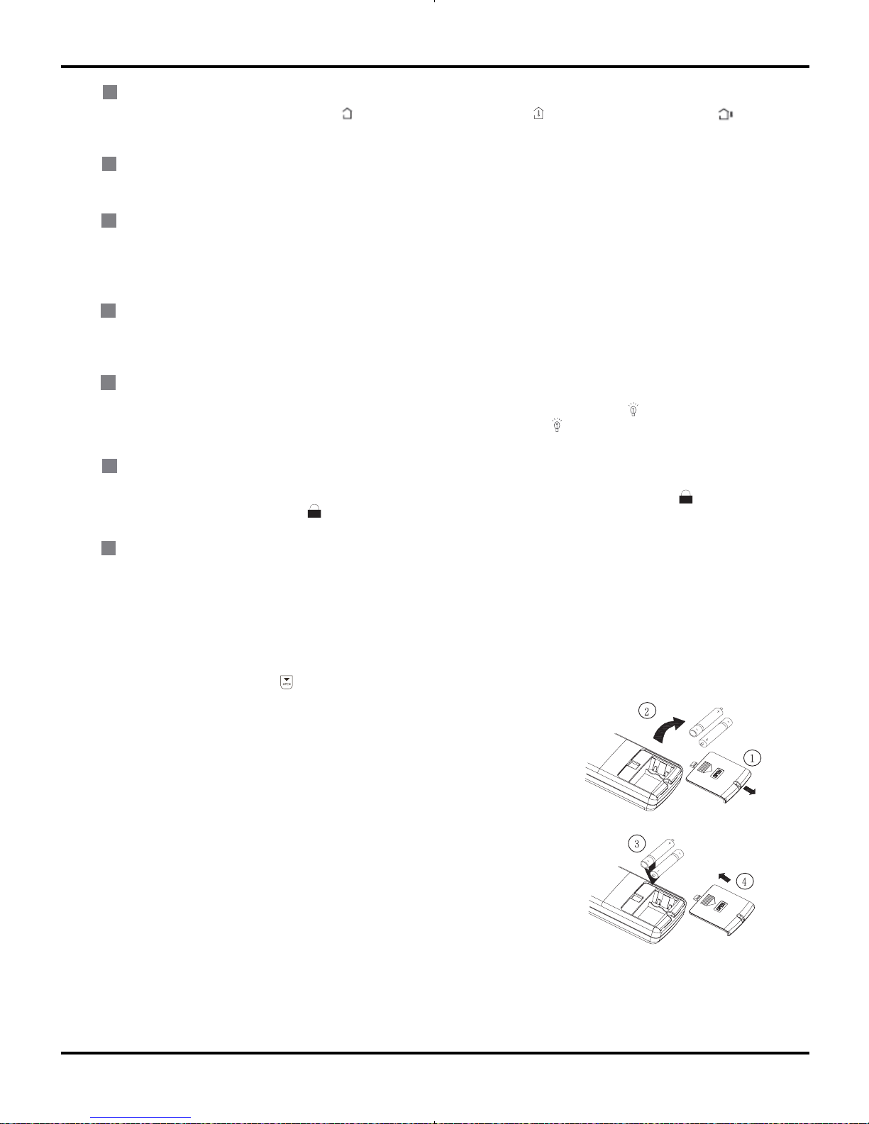
1.Slightly to press the place with , along the arrowhead direction to push the back
cover of wireless remote control. (As show in figure)
2. Take out the
used batteries. (As show in figure)
3. Insert two new AAA1.5V dry batteries, and pay attention to the polarity.
(As show in figure)
4. Reinstall the battery cover plate. (As show in figure)
TIMER OFF :
14
13
TEMP :
Once press this key to enter into TIMER OFF setup, in which case the TIMER OFF icon will blink.The method of setting
is the same as TIMER ON.
Press this button, could select displaying (the indoor setting temperature) , (indoor ambient temperature )or (
outdoor am-bient temperature) .The unit defaults not to display the icon. During operation of TEMP button, the set temperature is always displayed
6.2 Changing batteries and notices
14
6.3 Description of Each Control Operation
Function and Control
1. Temperature Parameters
Indoor preset temperature (Tpreset)
Indoor ambient temperature (T
amb.)
2. Basic Functions
Once energized, in no case should the compressor be restarted within less than 3 minutes. In the situation that memory function
is available, for the first energization, if the compressor is at stop before de-energization, the compressor will be started without
a 3-minute lag; if the compressor is in operation before de-energization, the compressor will be started with a 3-minute lag; and
once started, the compressor will not be stopped within 6 minutes regardless of changes in room temperature;
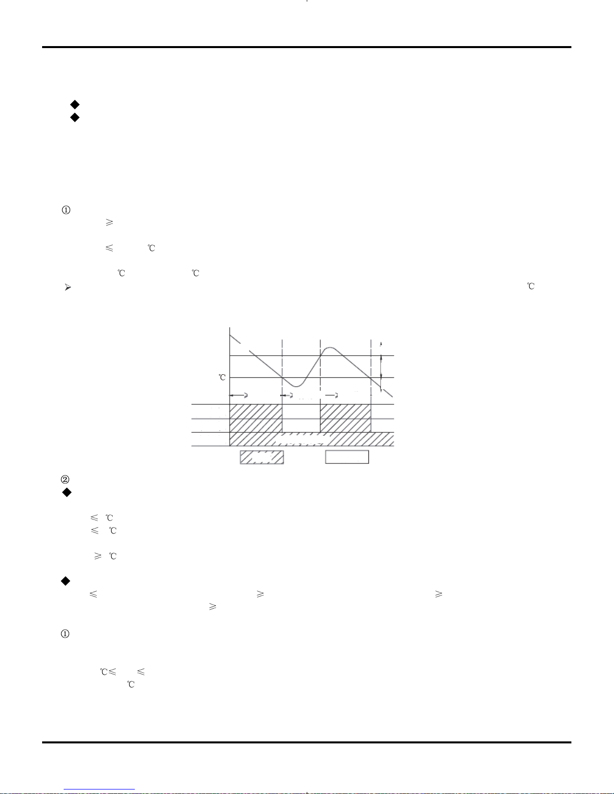
(1) Cooling Mode
Working conditions and process of cooling
When T
amb Tpreset, the unit will enter cooling operation, in which case the indoor fan, the outdoor fan and the compressor will
work and the indoor fan will run at preset speed.
When Tamb Tpreset -2 , the compressor will stop, the outdoor fan will stop with a time lag of 30s, and the indoor fan will run at
preset speed.
When Tpreset -2 < Tamb.< Tpreset +1 , the unit will remain at its previous state.
Under this mode, the four-way valve will be de-energized and temperature can be set within a range from 16 to 30
.
If the compressor is shut down for some reason, the indoor fan and the swing device will operate at original state.
Start cooling
Stop cooling
Compresso
r
Original working state
Run
Stop
Outdoor fan
Indoor fan
T
preset
T
reset
-2
T
amb
Preset fan speed
6 minutes
6 minutes
3 minutes
Protection
Freeze protection
Under cooling and dehumidifying mode, 6 minutes after the compressor is started:
If T
evap 2 , the compressor will operate at reduced frequency.
If T
evap -1 is detected for durative 3 minutes, the compressor will stop, and after 30 seconds, the outdoor fan will stop;
and under cooling mode, the indoor fan and the swing motor will remain at the original state.
If T evap. 6 and the compressor has remained at OFF for at least 3 minutes, the compressor will resume its original
operation state.
Total current up and frequency down protection
If Itotal
A, frequency rise will be allowed; if Itotal B, frequency rise will not be allowed; ifItotal C, the compressor will
run at reduced frequency; and if Itotal
D, the compressor will stop and the outdoor fan will stop with a time lag of 30s.
(2) Dehumidifying Mode
Working conditions and process of dehumidifying
If T
amb>Tpreset, the unit will enter cooling and dehumidifying mode, in which case the compressor and the outdoor fan will
operate and the indoor fan will run at low speed.
If Tpreset -2 Tamb Tpreset, the compressor remains at its original operation state.
If T
amb.< Tpreset -2 , the compressor will stop, the outdoor fan will stop with a time lag of 30s, and the indoor fan will
operate at low speed.
15
Function and Control
Protection
Protection is the same as that under the cooling mode.
(3) Heating Mode
Working conditions and process of heating
If T
amb. Tpreset +2 , the unit enters heating mode, in which case the four-way valve, the compressor and the outdoor fan will
operate simultaneously, and the indoor fan will run at preset speed in the condition of preset cold air prevention.
If T amb. Tpreset +5 , the compressor will stop, the outdoor fan will stop with a time lag of 30s, and the indoor fan will stop after 60-
second blow at low speed
If Tpreset +2 <T amb.< Tpreset +5 , the unit will maintain its original operating status.
Under this mode, the four-way valve is energized and temperature can be set within a range of 16 - 30
. The operating
symbol, the heating symbol and preset temperature are revealed on the display.
Condition and process of defrost
When duration of successive heating operation is more than 45 minutes, or accumulated heating time more than 90 minutes, and
one of the following conditions is reached, the unit will enter the defrost mode after 3 minutes.
a. T
outdoor amb. A , Toutdoor tube W ;
b. A
Toutdoor amb. <B , Toutdoor tube X ;
c. B
Toutdoor amb. <C , Toutdoor tube Y ;
d. T
outdoor amb.<C , Toutdoor tube Z
At that time, the indoor fan stops and the compressor stops, and after 30 seconds the outer fan will stop, and then after 30
seconds, the four-way valve will stop. After 30 seconds, the compressor is initiated for raising the frequency to defrost frequency.
When the compressor has operated under defrost mode for 7.5 minutes, or Touter tube E, the compressor will be converted to 53Hz
operation. After 30 seconds, the compressor will stop. And after another 30 seconds, the four-way valve will be opened, and after
60 seconds, the compressor and the outer fan will be started, the indoor fan will run under preset cold air prevention conditions,
and H1 will be displayed at temperature display area on the display panel. Defrost frequency is 70Hz.
3.Protection
Cold air prevention
The unit is started under heating mode (the compressor is ON):
In the case of T indoor amb. <24 : if T tube 40 and the indoor fan is at stop state, the indoor fan will begin to run at low speed with
a time lag of 2 minutes. Within 2 minutes, if T
tube>40 , the indoor fan also will run at low speed; and after 1-minute operation at
low speed, the indoor fan will be converted to operation at preset speed. Within 1-minute low speed operation or 2-minute non-
operation, if T tube>42 , the fan will run at present speed.
In the case of T indoor amb. 24 : if T tube 42 , the indoor fan will run at low speed, and after one minute, the indoor fan will be
converted to preset speed. Within one-minute low speed operation, if T
tube>42 , the indoor fan will be converted to preset speed.
Note: T
indoor amb. indicated in and refers to, under initially heating mode, the indoor ambient temperature before the
command to start the compressor is performed according to the program, or after the unit is withdrawn from defrost, the
indoor ambient temperature before the defrost symbol is cleared.
Total current up and frequency down protection
If the total current Itotal W, frequency rise will be allowed; if Itotal X, frequency rise will not be allowed; if Itotal Y, the compressor
will run at reduced frequency; and if I
total Z, the compressor will stop and the outdoor fan will stop with a time lag of 30s.
(4) Fan Mode
Under the mode, the indoor fan will run at preset speed and the compressor, the outdoor fan, the four-way valve and the electric
heater will stop.
Under the mode, temperature can be set within a range of 16 - 30 .
(5) AUTO Mode
Working conditions and process of AUTO mode
a. When Tamb. ≥26℃, the unit will run at cooling mode and the implied set temperature at this moment is 25℃.
b. When Tamb. ≤22℃, the cooling and heating unit will run at heating mode and the implied set temperature at this
moment is 20℃; cooling only unit will run at fan mode and the set temperature displayed is 25℃.
c. When 23℃≤Tamb. ≤25℃, the unit will keep the previous running mode; if it is first energized, it will run at fan mode.
d. After running at auto mode, the frequency of compressor in cooling operation is the same as that in cooling mode;
the frequency of compressor in heating operation is the same as that in heating mode.
 Loading...