

Gree GWH07PA-K3NNA3E, GWH07PA-K3NNA5E, GWH07PA-K3NNA1F, GWH07PA-K3NNA7F, GWH07PA-K3NNA5F Service Manual
...
GREE ELECTRIC APPLIANCES,INC.OF ZHUHAI
Change for Life
Service Manual

Service Manual
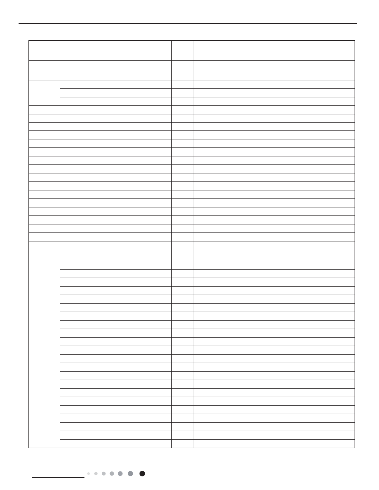
Table of Contents
Part
Ⅰ
: Technical Information
.......................................................................1
1. Summary
......................................................................................................................1
2. Specications
..........................................................................................................3
2.1 Specication Sheet ...........................................................................................................3
2.2 Capacity Curve in Different Outdoor Temperature .........................................................15
2.3 Cooling and Heating Data Sheet in Rated Frequency ...................................................15
3. Outline Dimension Diagram
......................................................................16
3.1 Indoor Unit ......................................................................................................................16
3.2 Outdoor Unit ...................................................................................................................17
4. Refrigerant System Diagram
....................................................................18
5. Electrical Part
.........................................................................................................19
5.1 Wiring Diagram ...............................................................................................................19
5.2 PCB Printed Diagram .....................................................................................................23
6. Function and Control
....................................................................................24
6.1 Remote Controller Introduction of YX1F ........................................................................24
6.2 Remote Controller Introduction of YV1F7 ......................................................................27
6.3 Remote Controller Introduction of YB1F2(XFAN) ........................................................... 31
6.4 Brief Description of Modes and Functions ......................................................................35
Part
Ⅱ
: Installation and Maintenance
.................................................40
7. Notes for Installation and Maintenance
..........................................40
8. Installation
................................................................................................................42
8.1 Installation Dimension Diagram ......................................................................................42
8.2 Installation Parts-checking ............................................................................................44
8.3 Selection of Installation Location ....................................................................................44
8.4 Electric Connection Requirement ...................................................................................44
8.5 Installation of Indoor Unit ................................................................................................44
8.6 Installation of Outdoor unit .............................................................................................47
8.7 Vacuum Pumping and Leak Detection ...........................................................................48
8.8 Check after Installation and Test operation ....................................................................48
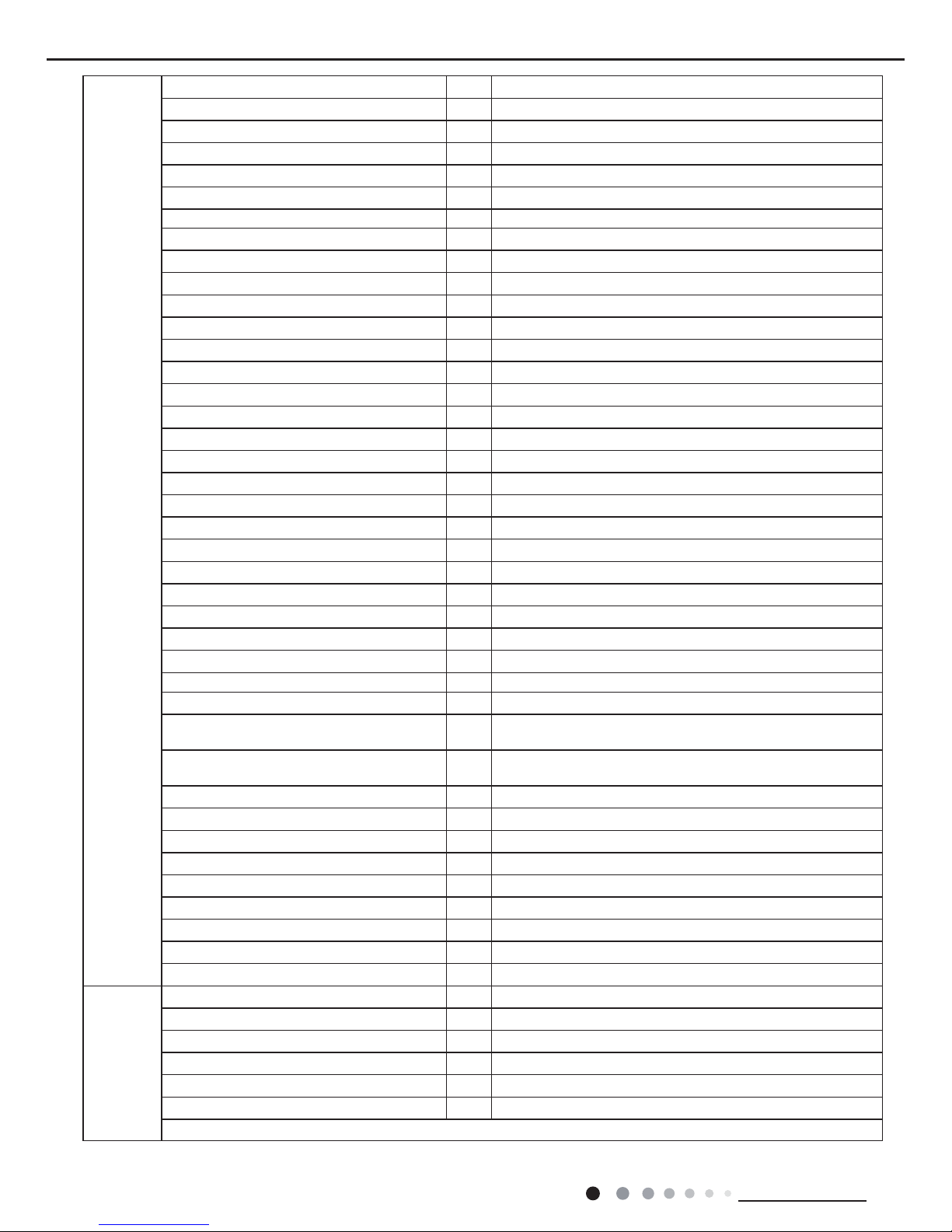
Table of Contents

Service Manual
9. Maintenance
............................................................................................................49
9.1 Error code .......................................................................................................................49
9.2 Procedure of Troubleshooting ........................................................................................50
9.3 Maintenance method for normal malfunction .................................................................54
10. Exploded View and Parts List
..............................................................56
10.1 Indoor Unit ....................................................................................................................56
10.2 Outdoor Unit .................................................................................................................83
11. Removal Procedure
.......................................................................................88
11.1 Removal Procedure of Indoor Unit ...............................................................................88
11.2 Removal Procedure of Outdoor Unit ............................................................................93
Appendix:
......................................................................................................................102
Appendix 1: Reference Sheet of Celsius and Fahrenheit ..................................................102
Appendix 2: Conguration of Connection Pipe ...................................................................102
Appendix 2: Pipe Expanding Method .................................................................................103
Appendix 4: List of Resistance for Temperature Sensor ....................................................104
Table of Contents
1
Technical Information
Service Manual
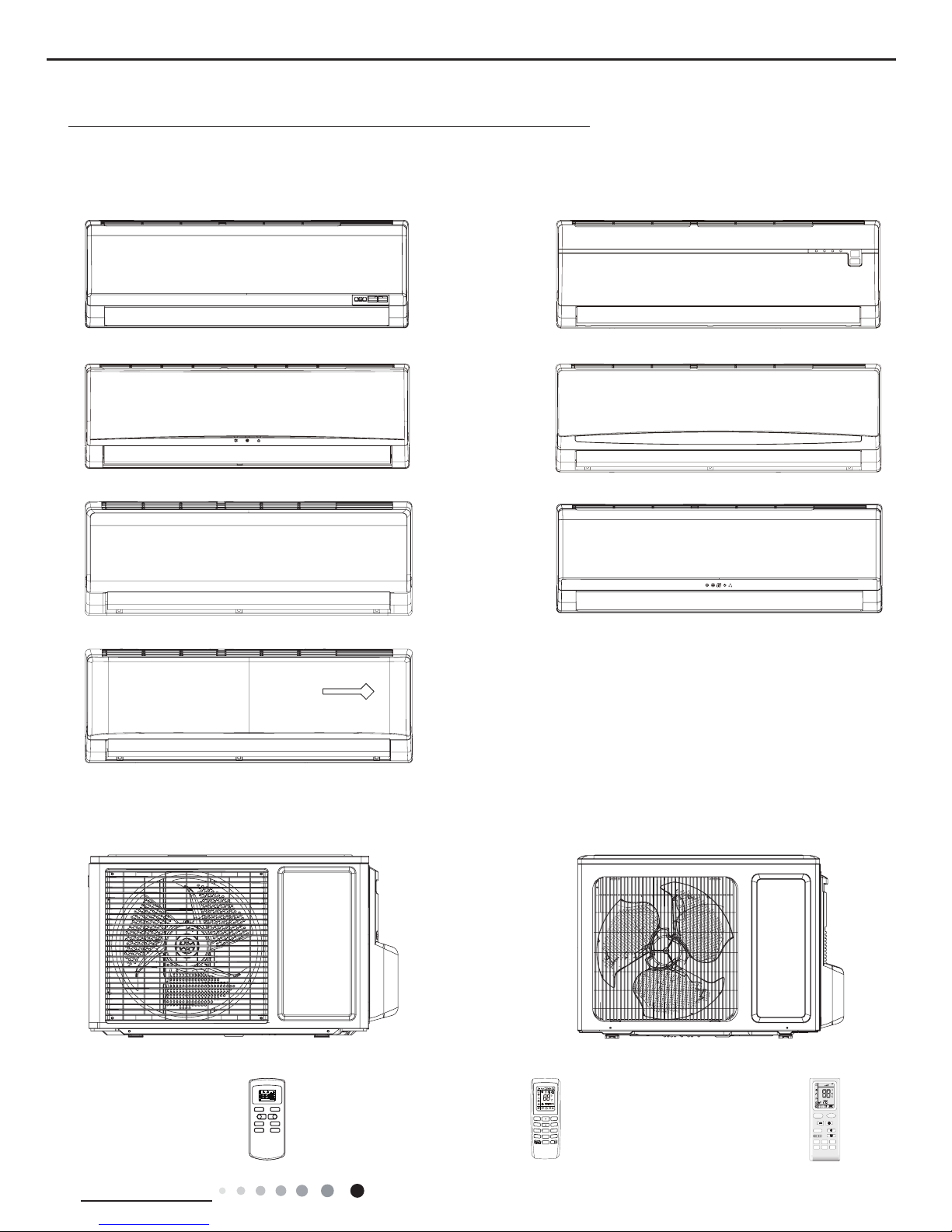
1. Summary
Indoor Unit:
Outdoor Unit:
07/09K 12K
Remote Controller:
YX1F YV1F7 YB1F2(XFAN)
Part
Ⅰ
: Technical Information
ON/OFF MODE
FAN SWING
SLEEP TIMER
+
-
AUTO
COOL
DRY
FAN
HEAT
T-ONT-OFF
SWING
SLEEP
LOCK
SPEED
A1 Panel
A3 Panel
A6 Panel
A9 Panel
A7 Panel
A5 Panel
A2 Panel
MODE
FAN
TIMER ON
TURBO
CLOCK
TEMP
IFEEL
ON/OFF
SWING
TIMER OFF
SLEEP
X-FAN
FAN
AUTO
OPER
HEALTH
AIR
FILTER
TURBO
ON/OFF
X-FAN
HOUR
HUMIDITY
ON/OFF
MODE
FAN
X-FAN
TURBO
TEMP
TIMER
SLEEP
LIGHT
2
Technical Information
Service Manual
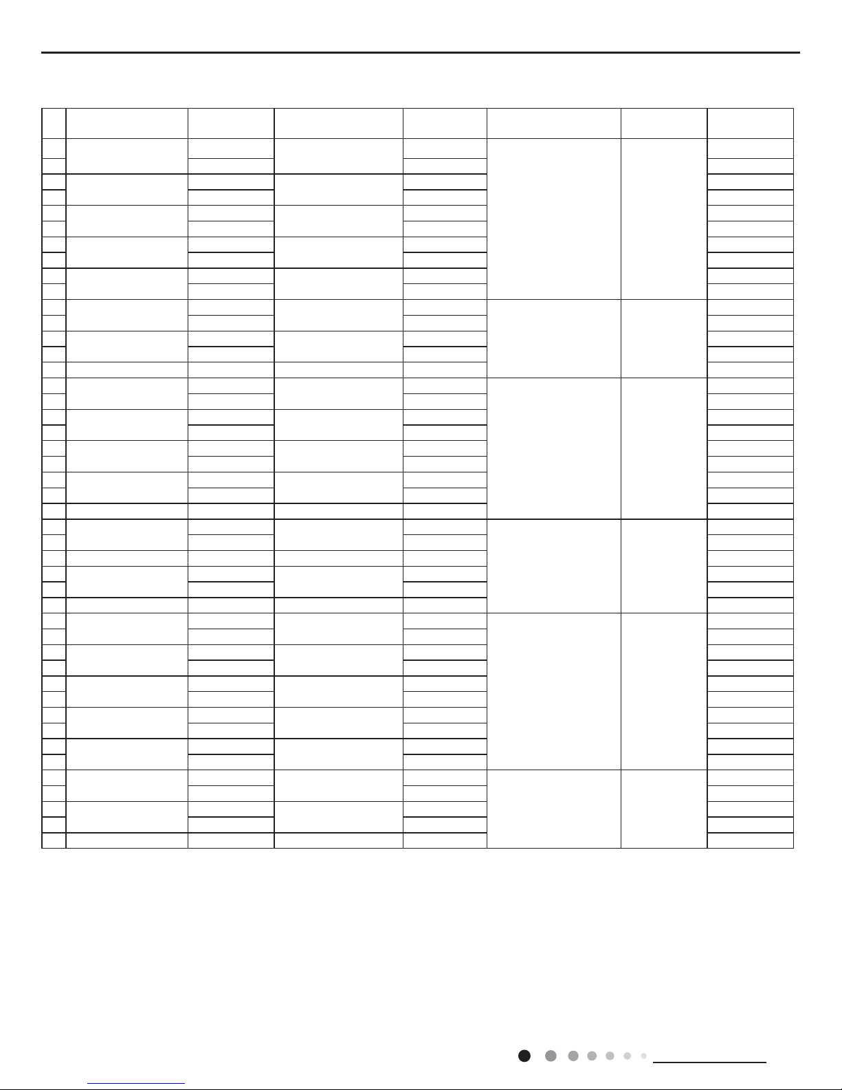
No. Model Product Code Model Product Code Model Product Code Remote
Controller
1
GWH07PA-K3NNA6E
CA430000600
GWH07PA-K3NNA6E/I
CA430N00600
GWH07NA-K3NNE4E/O CA403W01400
YX1F
2 CA430000601 CA430N00601 YV1F7
3
GWH07PA-K3NNA5E
CA417001600
GWH07PA-K3NNA5E/I
CA417N01600 YX1F
4 CA417001601 CA417N01601 YV1F7
5
GWH07PA-K3NNA2E
CA415001600
GWH07PA-K3NNA2E/I
CA415N01600 YX1F
6 CA415001601 CA415N01601 YV1F7
7
GWH07PA-K3NNA9E
CA429000700
GWH07PA-K3NNA9E/I
CA429N00700 YX1F
8 CA429000701 CA429N00701 YV1F7
9
GWH07PA-K3NNA3E
CA416001600
GWH07PA-K3NNA3E/I
CA416N01600 YX1F
10 CA416001601 CA416N01601 YV1F7
11
GWH07PA-K3NNA7F
CA428000600
GWH07PA-K3NNA7F/I
CA428N00600
GWH07NA-K3NNC7F/O CA195W06200
YX1F
12 CA428000601 CA428N00601 YB1F2(XFAN)
13
GWH07PA-K3NNA1F
CA414002200
GWH07PA-K3NNA1F/I
CA414N02200 YX1F
14 CA414002201 CA414N02201 YB1F2(XFAN)
15 GWH07PA-K3NNA5F CA417001900 GWH07PA-K3NNA5F/I CA417N01900 YX1F
16
GWH09PB-K3NNA6E
CA430000700
GWH09PB-K3NNA6E/I
CA430N00700
GWH09MA-K3NNE4E/O CA403W01500
YX1F
17 CA430000701 CA430N00701 YV1F7
18
GWH09PB-K3NNA5E
CA417001700
GWH09PB-K3NNA5E/I
CA417N01700 YX1F
19 CA417001701 CA417N01701 YV1F7
20
GWH09PB-K3NNA2E
CA415001700
GWH09PB-K3NNA2E/I
CA415N01700 YX1F
21 CA415001701 CA415N01701 YV1F7
22
GWH09PB-K3NNA9E
CA429000800
GWH09PB-K3NNA9E/I
CA429N00800 YX1F
23 CA429000801 CA429N00801 YV1F7
24 GWH09PB-K3NNA3E CA416001700 GWH09PB-K3NNA3E/I CA416N01700 YX1F
25
GWH09PA-K3NNA7F
CA428000700
GWH09PA-K3NNA7F/I
CA428N00700
GWH09NA-K3NNC7F/O CA195W06300
YX1F
26 CA428000701 CA428N00701 YB1F2(XFAN)
27 GWH09PA-K3NNA2F CA415003100 GWH09PA-K3NNA2F/I CA415N03100 YX1F
28
GWH09PA-K3NNA1F
CA414002301
GWH09PA-K3NNA1F/I
CA414N02301 YB1F2(XFAN)
29 CA414002300 CA414N02300 YX1F
30 GWH09PA-K3NNA5F CA417002000 GWH09PA-K3NNA5F/I CA417N02000 YX1F
31
GWH12PC-K3NNA6E
CA430000800
GWH12PC-K3NNA6E/I
CA430N00800
GWH12NC-K3NNE4E/O CA403W01600
YX1F
32 CA430000801 CA430N00801 YV1F7
33
GWH12PC-K3NNA5E
CA417001800
GWH12PC-K3NNA5E/I
CA417N01800 YX1F
34 CA417001801 CA417N01801 YV1F7
35
GWH12PC-K3NNA2E
CA415001800
GWH12PC-K3NNA2E/I
CA415N01800 YX1F
36 CA415001801 CA415N01801 YV1F7
37
GWH12PC-K3NNA9E
CA429000900
GWH12PC-K3NNA9E/I
CA429N00900 YX1F
38 CA429000901 CA429N00901 YV1F7
39
GWH12PC-K3NNA3E
CA416001800
GWH12PC-K3NNA3E/I
CA416N01800 YX1F
40 CA416001801 CA416N01801 YV1F7
41
GWH12PC-K3NNA7F
CA428000800
GWH12PC-K3NNA7F/I
CA428N00800
GWH12NC-K3NNC7F/O CA195W06400
YX1F
42 CA428000801 CA428N00801 YB1F2(XFAN)
43
GWH12PC-K3NNA1F
CA414002400
GWH12PC-K3NNA1F/I
CA414N02400 YX1F
44 CA414002401 CA414N02401 YB1F2(XFAN)
45 GWH12PC-K3NNA5F CA417002100 GWH12PC-K3NNA5F/I CA417N02100 YX1F
Model List:
3
Technical Information
Service Manual
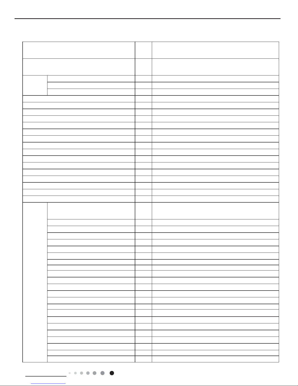
2. Specications
2.1 Specication Sheet
Model
1.GWH07PA-K3NNA6E 2.GWH07PA-K3NNA5E
3.GWH07PA-K3NNA2E 4.GWH07PA-K3NNA9E
5.GWH07PA-K3NNA3E
Product Code
1.CA430000600 CA430000601 2.CA417001600 CA417001601
3.CA415001600 CA415001601 4.CA429000700 CA429000701
5.CA416001600 CA416001601
Power
Supply
Rated Voltage V~ 220-240
Rated Frequency Hz 50
Phases 1
Power Supply Mode Indoor
Cooling Capacity W 2250
Heating Capacity W 2300
Cooling Power Input W 700
Heating Power Input W 637
Cooling Power Current A 4.88
Heating Power Current A 2.83
Rated Input W 1100
Rated Current A 5.75
Air Flow Volume(SH/H/M/L/SL) m3/h 400/360/320/290/-
Dehumidifying Volume L/h 0.6
EER W/W 3.21
COP W/W 3.61
SEER W/W /
HSPF W/W /
Application Area m
2
12-18
Indoor Unit
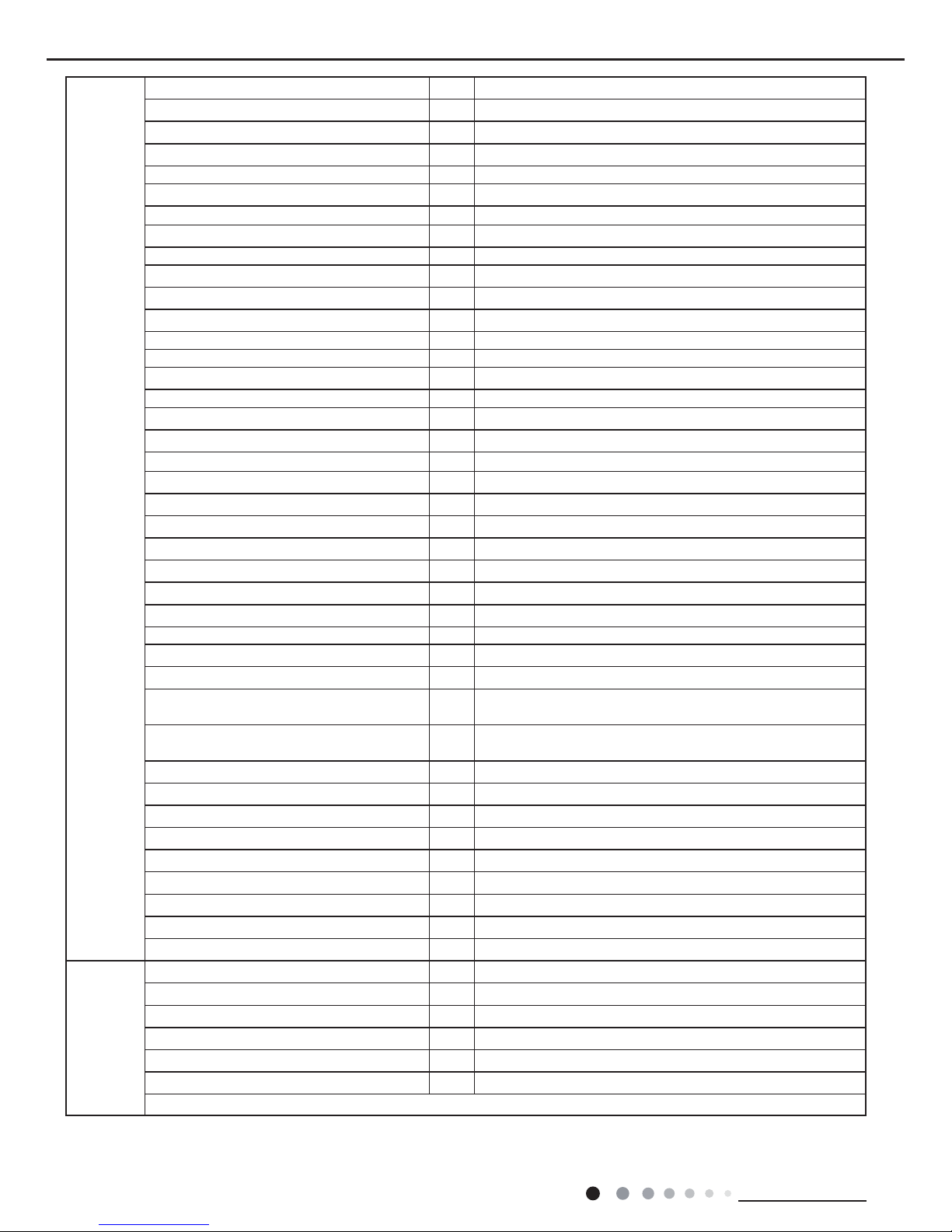
Model of Indoor Unit
1.GWH07PA-K3NNA6E/I 2.GWH07PA-K3NNA5E/I
3.GWH07PA-K3NNA2E/I 4.GWH07PA-K3NNA9E/I
5.GWH07PA-K3NNA3E/I
Fan Type Cross-ow
Diameter Length(DXL) mm Φ85X532
Fan Motor Cooling Speed(SH/H/M/L/SL) r/min 1390/1280/1180/1080/-
Fan Motor Heating Speed(SH/H/M/L/SL) r/min 1350/1250/1140/1040/-
Output of Fan Motor W 10
Fan Motor RLA A 0.13
Fan Motor Capacitor μF /
Input of Heater W /
Evaporator Form Aluminum Fin-copper Tube
Pipe Diameter mm Φ7
Row-n Gap mm 2-1.5
Coil Length (LXDXW) mm 526X25.4X228.6
Swing Motor Model MP24AA
Output of Swing Motor W 1.5
Fuse A 3.15
Sound Pressure Level (SH/H/M/L/SL) dB (A) 38/35/32/30/-
Sound Power Level (SH/H/M/L/SL) dB (A) 48/45/42/40/-
Dimension (WXHXD) mm 733X254X184
Dimension of Carton Box (LXWXH) mm 790X255X328
Dimension of Package (LXWXH) mm 793X258X343
Net Weight kg 8
Gross Weight kg 9.5
4
Technical Information
Service Manual
The above data is subject to change without notice; please refer to the nameplate of the unit.
Outdoor Unit
Model of Outdoor Unit GWH07NA-K3NNE4E/O
Product Code of Outdoor Unit CA403W01400
Compressor Manufacturer/Trademark Xi'an Qing'an Refrigeration Equipment Co.,Ltd
Compressor Model YZG-A082Y2T3
Compressor Oil RB68EP
Compressor Type Rotary
L.R.A. A 17
Compressor RLA A 3.35
Compressor Power Input W 705
Overload Protector B135-140-241E
Throttling Method Capillary
Operation Temp
o
C 16~30
Ambient Temp (Cooling)
o
C 18~43
Ambient Temp (Heating)
o
C -7~24
Condenser Form Aluminum Fin-copper Tube
Pipe Diameter mm Φ7
Rows-n Gap mm 1-1.4
Coil Length (LXDXW) mm 658.3X19.05X396
Fan Motor Speed rpm 950
Output of Fan Motor W 20
Fan Motor RLA A 0.25
Fan Motor Capacitor μF 1.5
Air Flow Volume of Outdoor Unit m3/h 1200
Fan Type Axial-ow
Fan Diameter mm Φ320
Defrosting Method Automatic Defrosting
Climate Type T1
Isolation I
Moisture Protection IP24
Permissible Excessive Operating Pressure for
the Discharge Side
MPa 4.3
Permissible Excessive Operating Pressure for
the Suction Side
MPa 2.5
Sound Pressure Level (H/M/L) dB (A) 48/-/-
Sound Power Level (H/M/L) dB (A) 58/-/-
Dimension (WXHXD) mm 720X428X310
Dimension of Carton Box (LXWXH) mm 765X350X475
Dimension of Package (LXWXH) mm 768X353X490
Net Weight kg 22.5
Gross Weight kg 24.5
Refrigerant R410A
Refrigerant Charge kg 0.6
Connection
Pipe
Length m 5
Gas Additional Charge g/m 20
Outer Diameter Liquid Pipe mm Φ6
Outer Diameter Gas Pipe mm Φ9.52
Max Distance Height m 5
Max Distance Length m 15
Note: The connection pipe applies metric diameter.

5
Technical Information
Service Manual
Model
1.GWH07PA-K3NNA7F 2.GWH07PA-K3NNA1F
3.GWH07PA-K3NNA5F
Product Code
1.CA428000600 CA428000601 2. CA414002200 CA414002201
3.CA417001900
Power
Supply
Rated Voltage V~ 220-240
Rated Frequency Hz 50
Phases 1
Power Supply Mode Indoor
Cooling Capacity W 2200
Heating Capacity W 2200
Cooling Power Input W 783
Heating Power Input W 650
Cooling Power Current A 4.88
Heating Power Current A 2.83
Rated Input W 1050
Rated Current A 5.75
Air Flow Volume(SH/H/M/L/SL) m3/h 400/360/320/290/-
Dehumidifying Volume L/h 0.6
EER W/W 2.81
COP W/W 3.39
SEER W/W /
HSPF W/W /
Application Area m
2
12-18
Indoor Unit
Model of Indoor Unit
1.GWH07PA-K3NNA7F/I 2.GWH07PA-K3NNA1F/I
3.GWH07PA-K3NNA5F/I
Fan Type Cross-ow
Diameter Length(DXL) mm Φ85X532
Fan Motor Cooling Speed(SH/H/M/L/SL) r/min 1390/1280/1180/1080/-
Fan Motor Heating Speed(SH/H/M/L/SL) r/min 1350/1250/1140/1040/-
Output of Fan Motor W 10
Fan Motor RLA A 0.13
Fan Motor Capacitor μF /
Input of Heater W /
Evaporator Form Aluminum Fin-copper Tube
Pipe Diameter mm Φ7
Row-n Gap mm 2-1.5
Coil Length (LXDXW) mm 526X25.4X228.6
Swing Motor Model MP24AA
Output of Swing Motor W 1.5
Fuse A 3.15
Sound Pressure Level (SH/H/M/L/SL) dB (A) 37/34/31/29/-
Sound Power Level (SH/H/M/L/SL) dB (A) 47/44/41/39/-
Dimension (WXHXD) mm 733X254X184
Dimension of Carton Box (LXWXH) mm 790X255X328
Dimension of Package (LXWXH) mm 793X258X343
Net Weight kg 8
Gross Weight kg 9.5
6
Technical Information
Service Manual
The above data is subject to change without notice; please refer to the nameplate of the unit.
Outdoor Unit
Model of Outdoor Unit GWH07NA-K3NNC7F/O
Product Code of Outdoor Unit CA195W06200
Compressor Manufacturer/Trademark Xi'an Qing'an Refrigeration Equipment Co.,Ltd
Compressor Model YZG-A082Y2T3
Compressor Oil RB68EP
Compressor Type Rotary
L.R.A. A 17
Compressor RLA A 3.35
Compressor Power Input W 705
Overload Protector B135-140-241E
Throttling Method Capillary
Operation Temp
o
C 16~30
Ambient Temp (Cooling)
o
C 18~43
Ambient Temp (Heating)
o
C -7~24
Condenser Form Aluminum Fin-copper Tube
Pipe Diameter mm Φ7
Rows-n Gap mm 1-1.4
Coil Length (LXDXW) mm 474X12.7X400
Fan Motor Speed rpm 950
Output of Fan Motor W 20
Fan Motor RLA A 0.25
Fan Motor Capacitor μF 1.5
Air Flow Volume of Outdoor Unit m3/h 1200
Fan Type Axial-ow
Fan Diameter mm Φ320
Defrosting Method Automatic Defrosting
Climate Type T1
Isolation I
Moisture Protection IP24
Permissible Excessive Operating Pressure for
the Discharge Side
MPa 4.3
Permissible Excessive Operating Pressure for
the Suction Side
MPa 2.5
Sound Pressure Level (H/M/L) dB (A) 50/-/-
Sound Power Level (H/M/L) dB (A) 60/-/-
Dimension (WXHXD) mm 720X428X310
Dimension of Carton Box (LXWXH) mm 765X350X475
Dimension of Package (LXWXH) mm 768X353X490
Net Weight kg 22
Gross Weight kg 24
Refrigerant R410A
Refrigerant Charge kg 0.5
Connection
Pipe
Length m 5
Gas Additional Charge g/m 20
Outer Diameter Liquid Pipe mm Φ6
Outer Diameter Gas Pipe mm Φ9.52
Max Distance Height m 5
Max Distance Length m 15
Note: The connection pipe applies metric diameter.
7
Technical Information
Service Manual
Model
1.GWH09PB-K3NNA6E 2.GWH09PB-K3NNA5E
3.GWH09PB-K3NNA2E 4.GWH09PB-K3NNA9E
5.GWH09PB-K3NNA3E
Product Code
1.CA430000700 CA430000701 2.CA417001700 CA417001701
3.CA415001700 CA415001701 4.CA429000800 CA429000801
5.CA416001700
Power
Supply
Rated Voltage V~ 220-240
Rated Frequency Hz 50
Phases 1
Power Supply Mode Indoor
Cooling Capacity W 2638
Heating Capacity W 2820
Cooling Power Input W 822
Heating Power Input W 781
Cooling Power Current A 4.45
Heating Power Current A 4.32
Rated Input W 1200
Rated Current A 6.43
Air Flow Volume(SH/H/M/L/SL) m3/h 450/400/320/250/-
Dehumidifying Volume L/h 1.2
EER W/W 3.21
COP W/W 3.61
SEER W/W /
HSPF W/W /
Application Area m
2
12-18
Indoor Unit
Model of Indoor Unit
1.GWH09PB-K3NNA6E/I 2.GWH09PB-K3NNA5E/I
3.GWH09PB-K3NNA2E/I 4.GWH09PB-K3NNA9E/I
5.GWH09PB-K3NNA3E/I
Fan Type Cross-ow
Diameter Length(DXL) mm Φ85X596
Fan Motor Cooling Speed(SH/H/M/L/SL) r/min 1350/1250/1100/950/-
Fan Motor Heating Speed(SH/H/M/L/SL) r/min 1350/1250/1100/1000/-
Output of Fan Motor W 10
Fan Motor RLA A 0.15
Fan Motor Capacitor μF 1
Input of Heater W /
Evaporator Form Aluminum Fin-copper Tube
Pipe Diameter mm Φ7
Row-n Gap mm 2-1.5
Coil Length (LXDXW) mm 589X25.4X266.7
Swing Motor Model MP24AA
Output of Swing Motor W 1.5
Fuse A 3.15
Sound Pressure Level (SH/H/M/L/SL) dB (A) 38/35/31/28/-
Sound Power Level (SH/H/M/L/SL) dB (A) 48/45/41/38/-
Dimension (WXHXD) mm 790X265X179
Dimension of Carton Box (LXWXH) mm 870X255X350
Dimension of Package (LXWXH) mm 873X258X365
Net Weight kg 8
Gross Weight kg 10
8
Technical Information
Service Manual
The above data is subject to change without notice; please refer to the nameplate of the unit.
Outdoor Unit
Model of Outdoor Unit GWH09MA-K3NNE4E/O
Product Code of Outdoor Unit CA403W01500
Compressor Manufacturer/Trademark ZHUHAI LINDA COMPRESSOR CO.,LTD
Compressor Model QXA-B102C130
Compressor Oil RB68EP
Compressor Type Rotary
L.R.A. A 17
Compressor RLA A 3.9
Compressor Power Input W 850
Overload Protector INTERNAL
Throttling Method Capillary
Operation Temp
o
C 16~30
Ambient Temp (Cooling)
o
C 18~43
Ambient Temp (Heating)
o
C -7~24
Condenser Form Aluminum Fin-copper Tube
Pipe Diameter mm Φ7
Rows-n Gap mm 1-1.4
Coil Length (LXDXW) mm 658.3X19.05X396
Fan Motor Speed rpm 950
Output of Fan Motor W 20
Fan Motor RLA A 0.25
Fan Motor Capacitor μF 1.5
Air Flow Volume of Outdoor Unit m3/h 1200
Fan Type Axial-ow
Fan Diameter mm Φ320
Defrosting Method Automatic Defrosting
Climate Type T1
Isolation I
Moisture Protection IP24
Permissible Excessive Operating Pressure for
the Discharge Side
MPa 4.3
Permissible Excessive Operating Pressure for
the Suction Side
MPa 2.5
Sound Pressure Level (H/M/L) dB (A) 49/-/-
Sound Power Level (H/M/L) dB (A) 59/-/-
Dimension (WXHXD) mm 720X428X310
Dimension of Carton Box (LXWXH) mm 765X350X475
Dimension of Package (LXWXH) mm 768X353X490
Net Weight kg 26
Gross Weight kg 28
Refrigerant R410A
Refrigerant Charge kg 0.63
Connection
Pipe
Length m 5
Gas Additional Charge g/m 20
Outer Diameter Liquid Pipe mm Φ6
Outer Diameter Gas Pipe mm Φ9.52
Max Distance Height m 5
Max Distance Length m 15
Note: The connection pipe applies metric diameter.
9
Technical Information
Service Manual
Model
1.GWH09PA-K3NNA7F 2.GWH09PA-K3NNA2F
3.GWH09PA-K3NNA1F 4.GWH09PA-K3NNA5F
Product Code
1.CA428000700 CA428000701 2.CA415003100
3.CA414002301 CA414002300 4.CA417002000
Power
Supply
Rated Voltage V~ 220-240
Rated Frequency Hz 50
Phases 1
Power Supply Mode Indoor
Cooling Capacity W 2638
Heating Capacity W 2814
Cooling Power Input W 939
Heating Power Input W 853
Cooling Power Current A 3.64
Heating Power Current A 3.46
Rated Input W 1350
Rated Current A 4.97
Air Flow Volume(SH/H/M/L/SL) m3/h 450/400/320/250/-
Dehumidifying Volume L/h 0.8
EER W/W 2.81
COP W/W 3.39
SEER W/W /
HSPF W/W /
Application Area m
2
12-18
Indoor Unit
Model of Indoor Unit
1.GWH09PA-K3NNA7F/I 2.GWH09PA-K3NNA2F/I
3.GWH09PA-K3NNA1F/I 4.GWH09PA-K3NNA5F/I
Fan Type Cross-ow
Diameter Length(DXL) mm Φ85X596
Fan Motor Cooling Speed(SH/H/M/L/SL) r/min 1390/1280/1180/1080/-
Fan Motor Heating Speed(SH/H/M/L/SL) r/min 1350/1250/1140/1040/-
Output of Fan Motor W 10
Fan Motor RLA A 0.15
Fan Motor Capacitor μF 1
Input of Heater W /
Evaporator Form Aluminum Fin-copper Tube
Pipe Diameter mm Φ7
Row-n Gap mm 2-1.5
Coil Length (LXDXW) mm 589X25.4X266.7
Swing Motor Model MP24AA
Output of Swing Motor W 1.5
Fuse A 3.15
Sound Pressure Level (SH/H/M/L/SL) dB (A) 37/34/31/29/-
Sound Power Level (SH/H/M/L/SL) dB (A) 47/44/41/39/-
Dimension (WXHXD) mm 733X254X184
Dimension of Carton Box (LXWXH) mm 790X255X328
Dimension of Package (LXWXH) mm 793X258X343
Net Weight kg 8
Gross Weight kg 9.5

10
Technical Information
Service Manual
Outdoor Unit
Model of Outdoor Unit GWH09NA-K3NNC7F/O
Product Code of Outdoor Unit CA195W06300
Compressor Manufacturer/Trademark ZHUHAI LANDA COMPRESSOR CO.,LTD
Compressor Model QXA-B106C130A
Compressor Oil RB68EP
Compressor Type Rotary
L.R.A. A 17
Compressor RLA A 4.1
Compressor Power Input W 875
Overload Protector UP3-20
Throttling Method Capillary
Operation Temp
o
C 16~30
Ambient Temp (Cooling)
o
C 18~43
Ambient Temp (Heating)
o
C -7~24
Condenser Form Aluminum Fin-copper Tube
Pipe Diameter mm Φ7.94
Rows-n Gap mm 1-1.4
Coil Length (LXDXW) mm 658X19.05X396
Fan Motor Speed rpm 950
Output of Fan Motor W 20
Fan Motor RLA A 0.25
Fan Motor Capacitor μF 1.5
Air Flow Volume of Outdoor Unit m3/h 1200
Fan Type Axial-ow
Fan Diameter mm Φ320
Defrosting Method Automatic Defrosting
Climate Type T1
Isolation I
Moisture Protection IP24
Permissible Excessive Operating Pressure for
the Discharge Side
MPa 4.3
Permissible Excessive Operating Pressure for
the Suction Side
MPa 2.5
Sound Pressure Level (H/M/L) dB (A) 50/-/-
Sound Power Level (H/M/L) dB (A) 60/-/-
Dimension (WXHXD) mm 720X428X310
Dimension of Carton Box (LXWXH) mm 765X350X475
Dimension of Package (LXWXH) mm 768X353X490
Net Weight kg 25.5
Gross Weight kg 27.5
Refrigerant R410A
Refrigerant Charge kg 0.68
Connection
Pipe
Length m 5
Gas Additional Charge g/m 20
Outer Diameter Liquid Pipe mm Φ6
Outer Diameter Gas Pipe mm Φ9.52
Max Distance Height m 5
Max Distance Length m 15
Note: The connection pipe applies metric diameter.
The above data is subject to change without notice; please refer to the nameplate of the unit.
11
Technical Information
Service Manual
Model
1.GWH12PC-K3NNA6E 2.GWH12PC-K3NNA5E
3.GWH12PC-K3NNA2E 4.GWH12PC-K3NNA9E
5.GWH12PC-K3NNA3E
Product Code
1.CA430000800 CA430000801 2.CA417001800 CA417001801
3.CA415001800 CA415001801 4.CA429000900 CA429000901
5.CA416001800 CA416001801
Power
Supply
Rated Voltage V~ 220-240
Rated Frequency Hz 50
Phases 1
Power Supply Mode Indoor
Cooling Capacity W 3223
Heating Capacity W 3516
Cooling Power Input W 1004
Heating Power Input W 973
Cooling Power Current A 5.0
Heating Power Current A 4.5
Rated Input W 1500
Rated Current A 6.43
Air Flow Volume(SH/H/M/L/SL) m3/h 650/550/450/330/-
Dehumidifying Volume L/h 1.2
EER W/W 3.0
COP W/W 4.0
SEER W/W /
HSPF W/W /
Application Area m
2
12-18
Indoor Unit
Model of Indoor Unit
1.GWH12PC-K3NNA6E/I 2.GWH12PC-K3NNA5E/I
3.GWH12PC-K3NNA2E/I 4.GWH12PC-K3NNA9E/I
5.GWH12PC-K3NNA3E/I
Fan Type Cross-ow
Diameter Length(DXL) mm Φ92X645
Fan Motor Cooling Speed(SH/H/M/L/SL) r/min 1350/1250/1100/950/-
Fan Motor Heating Speed(SH/H/M/L/SL) r/min 1190/1150/1050/920/-
Output of Fan Motor W 20
Fan Motor RLA A 0.2
Fan Motor Capacitor μF 1
Input of Heater W /
Evaporator Form Aluminum Fin-copper Tube
Pipe Diameter mm Φ7
Row-n Gap mm 2-1.5
Coil Length (LXDXW) mm 645X25.4X266.7
Swing Motor Model MP24AA
Output of Swing Motor W 1.5
Fuse A 3.15
Sound Pressure Level (SH/H/M/L/SL) dB (A) 42/39/36/33/-
Sound Power Level (SH/H/M/L/SL) dB (A) 52/49/46/43/-
Dimension (WXHXD) mm 845X275X180
Dimension of Carton Box (LXWXH) mm 923X264X356
Dimension of Package (LXWXH) mm 926X267X371
Net Weight kg 9.5
Gross Weight kg 11.5

12
Technical Information
Service Manual
Outdoor Unit
Model of Outdoor Unit GWH12NC-K3NNE4E/O
Product Code of Outdoor Unit CA403W01600
Compressor Manufacturer/Trademark ZHUHAI LANDA COMPRESSOR CO., LTD
Compressor Model QXA-B120C150
Compressor Oil RB68EP
Compressor Type Rotary
L.R.A. A 22
Compressor RLA A 4.7
Compressor Power Input W 1020
Overload Protector INTERNAL
Throttling Method Capillary
Operation Temp
o
C 16~30
Ambient Temp (Cooling)
o
C 18~43
Ambient Temp (Heating)
o
C -7~24
Condenser Form Aluminum Fin-copper Tube
Pipe Diameter mm Φ7.94
Rows-n Gap mm 1-1.4
Coil Length (LXDXW) mm 697X19.05X506
Fan Motor Speed rpm 850
Output of Fan Motor W 35
Fan Motor RLA A 0.33
Fan Motor Capacitor μF 2.5
Air Flow Volume of Outdoor Unit m3/h 1600
Fan Type Axial-o
Fan Diameter mm Φ395
Defrosting Method Automatic Defrosting
Climate Type T1
Isolation I
Moisture Protection IP24
Permissible Excessive Operating Pressure for
the Discharge Side
MPa 4.3
Permissible Excessive Operating Pressure for
the Suction Side
MPa 2.5
Sound Pressure Level (H/M/L) dB (A) 52/-/-
Sound Power Level (H/M/L) dB (A) 62/-/-
Dimension (WXHXD) mm 776X540X320
Dimension of Carton Box (LXWXH) mm 820X355X580
Dimension of Package (LXWXH) mm 823X358X595
Net Weight kg 29
Gross Weight kg 31.5
Refrigerant R410A
Refrigerant Charge kg 0.83
Connection
Pipe
Length m 5
Gas Additional Charge g/m 20
Outer Diameter Liquid Pipe mm Φ6
Outer Diameter Gas Pipe mm Φ12
Max Distance Height m 10
Max Distance Length m 20
Note: The connection pipe applies metric diameter.
The above data is subject to change without notice; please refer to the nameplate of the unit.

13
Technical Information
Service Manual
Model
1.GWH12PC-K3NNA7F 2.GWH12PC-K3NNA1F
3.GWH12PC-K3NNA5F
Product Code
1.CA428000800 CA428000801 2.CA414002400 CA414002401
3.CA417002100
Power
Supply
Rated Voltage V~ 220-240
Rated Frequency Hz 50
Phases 1
Power Supply Mode Indoor
Cooling Capacity W 3223
Heating Capacity W 3370
Cooling Power Input W 1146
Heating Power Input W 1049
Cooling Power Current A 5.1
Heating Power Current A 4.39
Rated Input W 1450
Rated Current A 7.39
Air Flow Volume(SH/H/M/L/SL) m3/h 650/550/450/330/-
Dehumidifying Volume L/h 1.2
EER W/W 3.0
COP W/W 3.0
SEER W/W /
HSPF W/W /
Application Area m
2
12-18
Indoor Unit
Model of Indoor Unit
1.GWH12PC-K3NNA7F/I 2.GWH12PC-K3NNA1F/I
3.GWH12PC-K3NNA5F/I
Fan Type Cross-ow
Diameter Length(DXL) mm Φ92X645
Fan Motor Cooling Speed(SH/H/M/L/SL) r/min 1350/1250/1100/950/-
Fan Motor Heating Speed(SH/H/M/L/SL) r/min 1190/1150/1050/920/-
Output of Fan Motor W 20
Fan Motor RLA A 0.2
Fan Motor Capacitor μF 1
Input of Heater W /
Evaporator Form Aluminum Fin-copper Tube
Pipe Diameter mm Φ7
Row-n Gap mm 2-1.5
Coil Length (LXDXW) mm 645X25.4X266.7
Swing Motor Model MP24AA
Output of Swing Motor W 1.5
Fuse A 3.15
Sound Pressure Level (SH/H/M/L/SL) dB (A) 45/39/36/33/-
Sound Power Level (SH/H/M/L/SL) dB (A) 55/49/46/43/-
Dimension (WXHXD) mm 845X275X180
Dimension of Carton Box (LXWXH) mm 923X264X356
Dimension of Package (LXWXH) mm 926X267X371
Net Weight kg 9
Gross Weight kg 11
14
Technical Information
Service Manual
Outdoor Unit
Model of Outdoor Unit GWH12NC-K3NNC7F/O
Product Code of Outdoor Unit CA195W06400
Compressor Manufacturer/Trademark ZHUHAI LANDA COMPRESSOR CO., LTD
Compressor Model QXA-B120C150
Compressor Oil RB68EP
Compressor Type Rotary
L.R.A. A 22
Compressor RLA A 4.7
Compressor Power Input W 1020
Overload Protector INTERNAL
Throttling Method Capillary
Operation Temp
o
C 16~30
Ambient Temp (Cooling)
o
C 18~43
Ambient Temp (Heating)
o
C -7~24
Condenser Form Aluminum Fin-copper Tube
Pipe Diameter mm Φ7
Rows-n Gap mm 1-1.4
Coil Length (LXDXW) mm 721.5X12.7X495
Fan Motor Speed rpm 850
Output of Fan Motor W 35
Fan Motor RLA A 0.33
Fan Motor Capacitor μF 2.5
Air Flow Volume of Outdoor Unit m3/h 1600
Fan Type Axial-o
Fan Diameter mm Φ395
Defrosting Method Automatic Defrosting
Climate Type T1
Isolation I
Moisture Protection IP24
Permissible Excessive Operating Pressure for
the Discharge Side
MPa 4.3
Permissible Excessive Operating Pressure for
the Suction Side
MPa 2.5
Sound Pressure Level (H/M/L) dB (A) 52/-/-
Sound Power Level (H/M/L) dB (A) 62/-/-
Dimension (WXHXD) mm 776X540X320
Dimension of Carton Box (LXWXH) mm 820X355X580
Dimension of Package (LXWXH) mm 823X358X595
Net Weight kg 29
Gross Weight kg 31.5
Refrigerant R410A
Refrigerant Charge kg 0.8
Connection
Pipe
Length m 5
Gas Additional Charge g/m 20
Outer Diameter Liquid Pipe mm Φ6
Outer Diameter Gas Pipe mm Φ9.52
Max Distance Height m 10
Max Distance Length m 20
Note: The connection pipe applies metric diameter.
The above data is subject to change without notice; please refer to the nameplate of the unit.
15
Technical Information
Service Manual
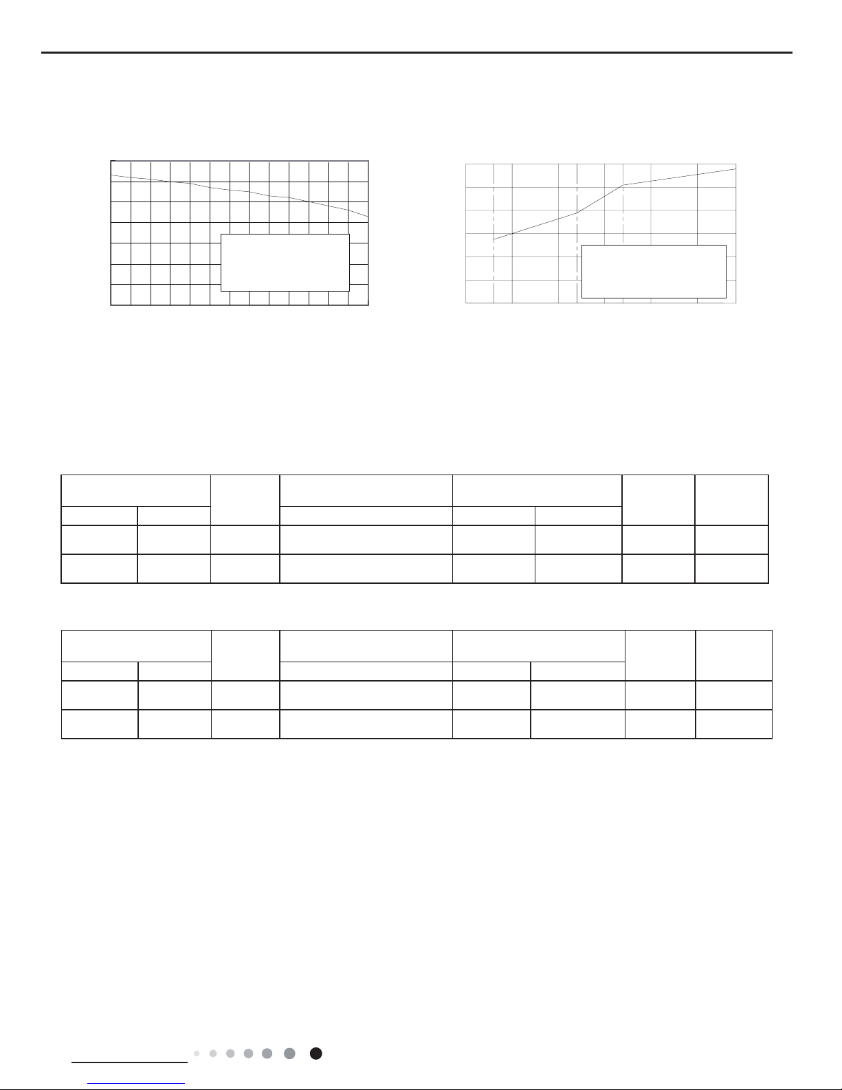
2.2 Capacity Curve in Different Outdoor Temperature
2.3 Cooling and Heating Data Sheet in Rated Frequency
Heating
Rated heatling condition(°C)
(DB/WB)
Model
Pressure of gas pipe connecting
indoor and outdoor unit
Inlet and outlet pipe temperature
of heat exchanger
Fan speed of
indoor unit
Fan speed of
outdoor unit
Indoor Outdoor P (MPa) T1 (°C) T2 (°C)
20/- 7/6 07/09K 3.5~3.8
in:75~85
out:37~43
in:1~3
out:2~5
Super High High
20/- 7/6 12K 2.3~2.5
in:75~85
out:37~43
in:1~3
out:2~5
Super High High
40
50
60
70
80
90
100
110
32 33 34 35 36 37 38 39 40 41 42 43 44 45
Outdoor temp.( ) Outdoor temp.( )
)
%
(
o i t a r y t i c a p a
C
)%(oitar yticapaC
Condition
Indoor:DB27
°C
WB19
°C
°C
°C
Indoor air flow: Super High
Pipe length:5m
157-7 -5 02
24
0
20
40
60
80
100
120
-10510
Condition Heating
Indoor:DB20
°C
Indoor air flow: Super High
Pipe length:5m
Cooling Heating
Rated cooling condition(°C)
(DB/WB)
Model
Pressure of gas pipe connecting
indoor and outdoor unit
Inlet and outlet pipe temperature
of heat exchanger
Fan speed of
indoor unit
Fan speed of
outdoor unit
Indoor Outdoor P (MPa) T1 (°C) T2 (°C)
27/19 35/24 07/09K 0.85~1.0
in:8~11
out:11~14
in:75~85
out:37~43
Super High High
27/19 35/24 12K 0.9~1.1
in:8~11
out:11~14
in:75~85
out:37~43
Super High High
Cooling
Instruction:
T1: Inlet and outlet pipe temperature of evaporator
T2: Inlet and outlet pipe temperature of condenser
P: Pressure at the side of big valve
Connection pipe length: 5 m.
16
Technical Information
Service Manual
25
562
146
22
40
40
40
65
71
76
605
37
148
40
43
43
Φ55
Φ55
Φ55
Φ55
Φ55
Φ55
542
143
80
131
172
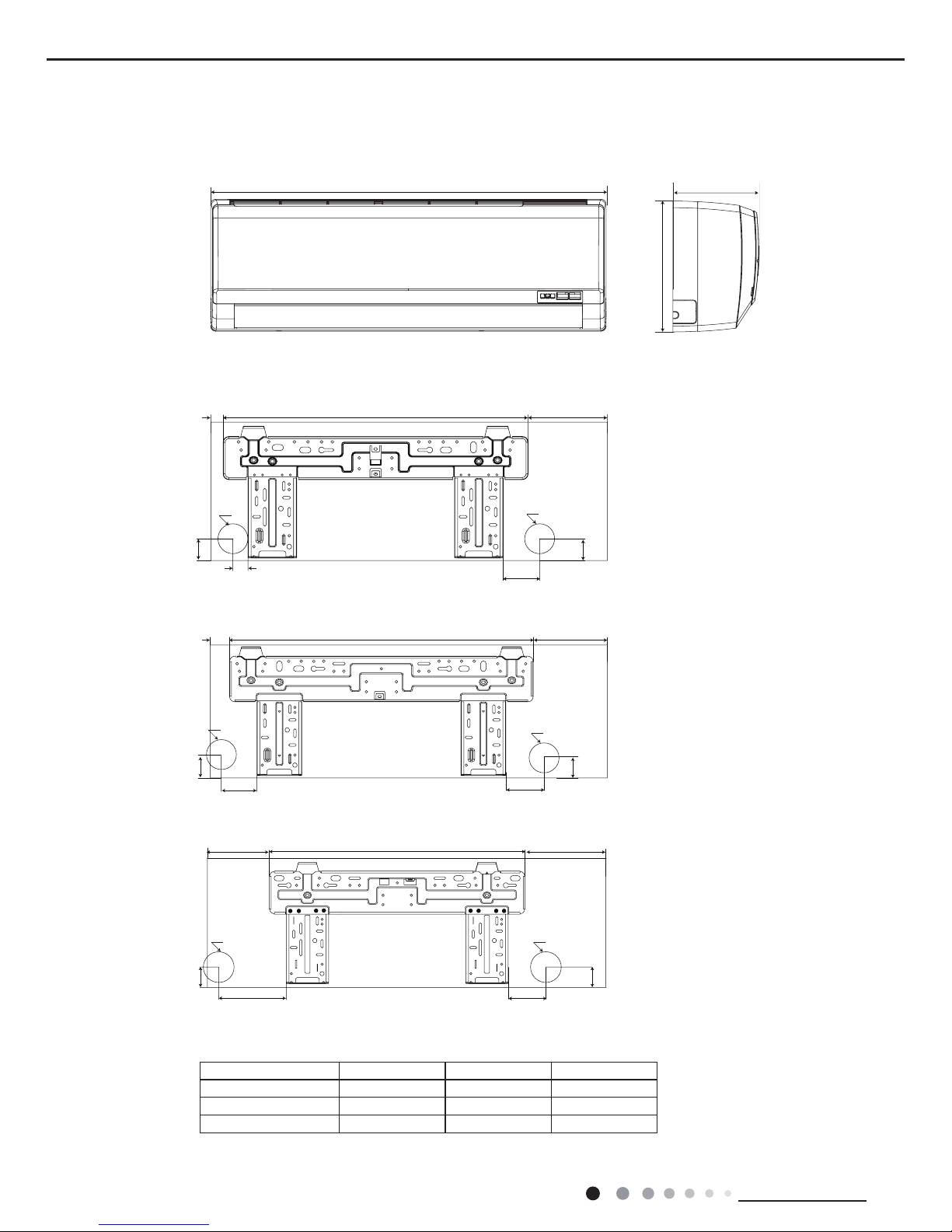
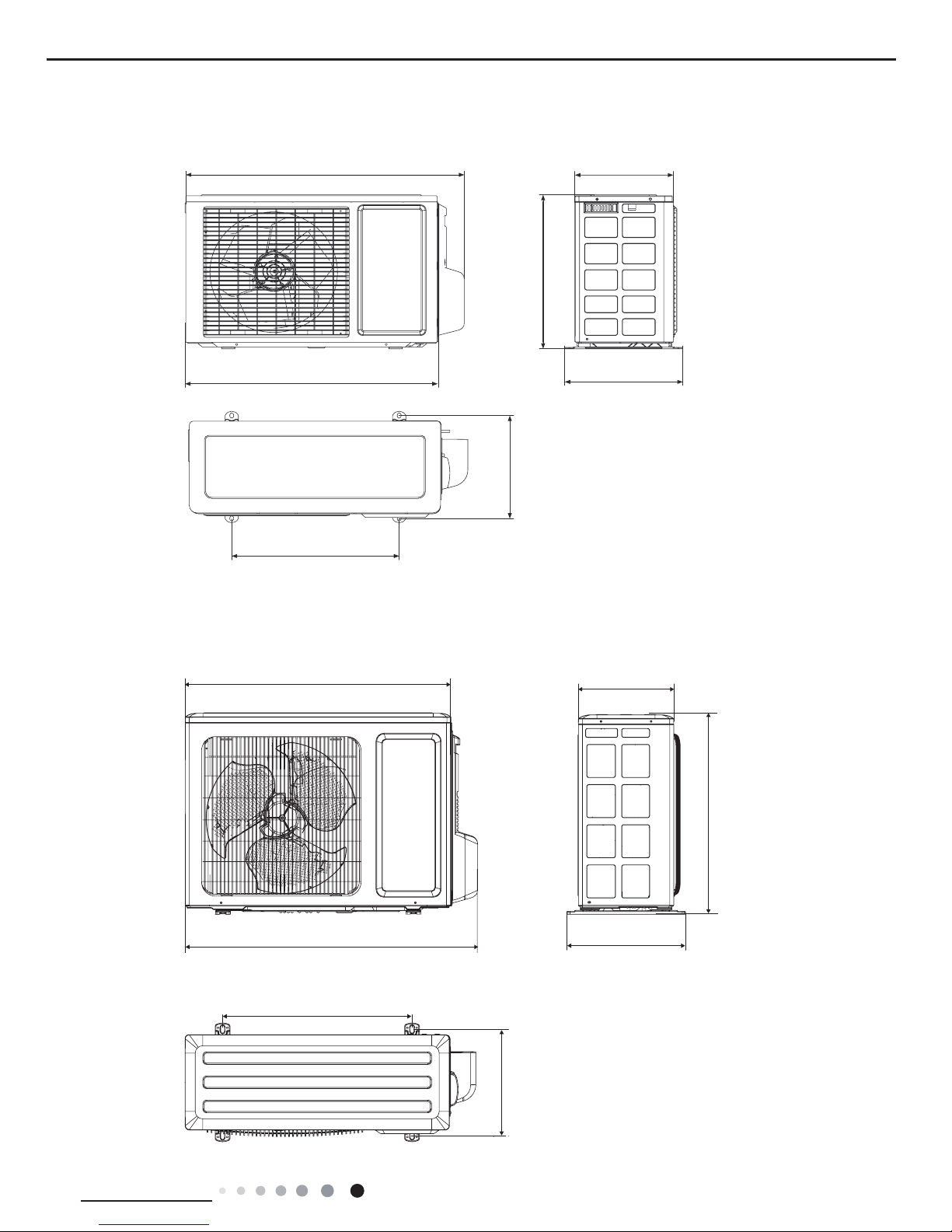
3. Outline Dimension Diagram
3.1 Indoor Unit
Unit:mm
12K
09K(PB)
07K/09K(PA)
W
H
D
Model W H D
07K/09K(PA) 733 254 184
09K(PB) 790 265 179
12K 845 275 180
17
Technical Information
Service Manual
3.2 Outdoor Unit
Unit:mm
Unit:mm
286
255
428
660
310
440
720
712
776
510
320
257
6 8 2
045
07K/09K
12K
18
Technical Information
Service Manual
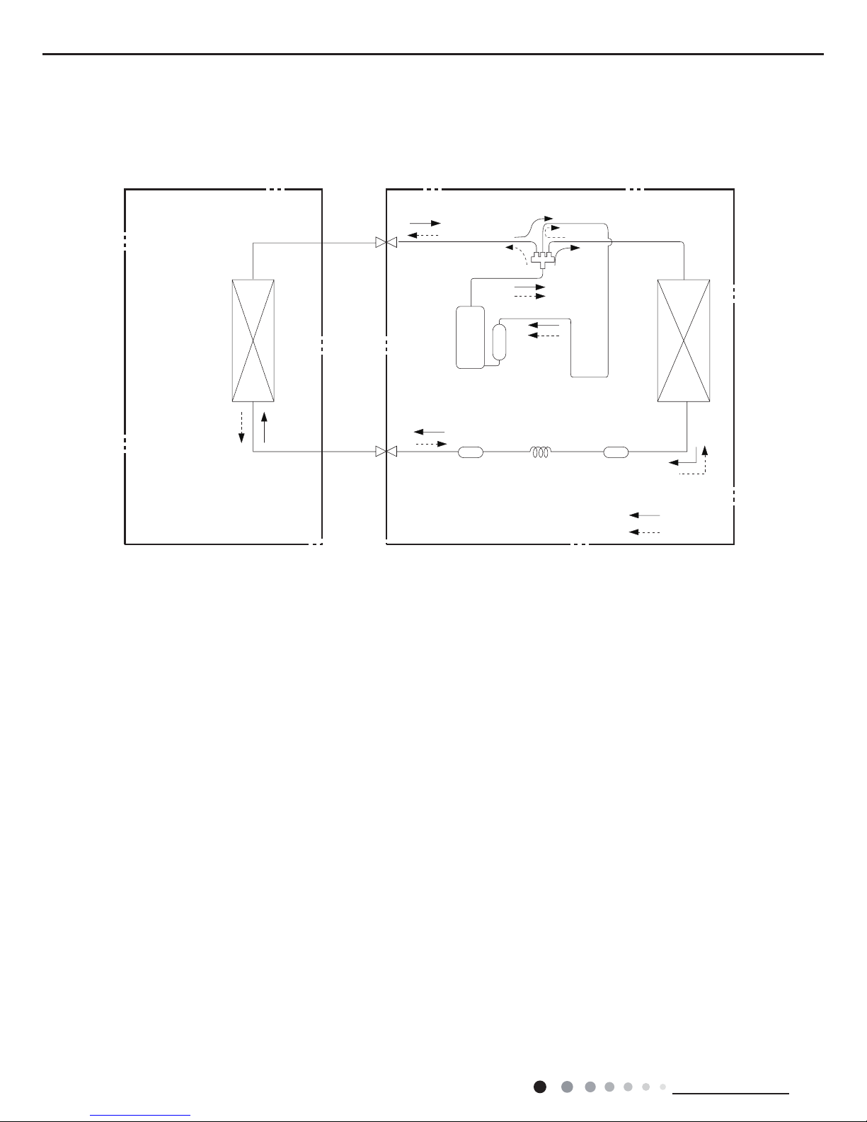
4. Refrigerant System Diagram
Cooling and heating model
Connection pipe specication:
Liquid pipe:1/4" (6mm)
Gas pipe:3/8" (9.52mm)All models except:12K(A2/A3/A5/A6/A9 panel)
Gas pipe:1/2" (12mm)12K(A2/A3/A5/A6/A9 panel)
Indoor unit
Outdoor unit
Indoor unit
Outdoor unit
COOLING
HEATING
Accumlator
4-Way valve
COOLING
Discharge
Suction
Discharge
Suction
Heat
exchanger
(evaporator)
Heat
exchanger
(evaporator)
Heat
exchanger
(condenser)
Heat
exchanger
(condenser)
Valve
Valve
Valve
Valve
Liquid pipe
side
Gas pipe
side
Liquid pipe
side
Gas pipe
side
Compressor
Accumlator
Compressor
Strainer
Strainer
Capillary
StrainerCapillary
19
Technical Information
Service Manual
5. Electrical Part
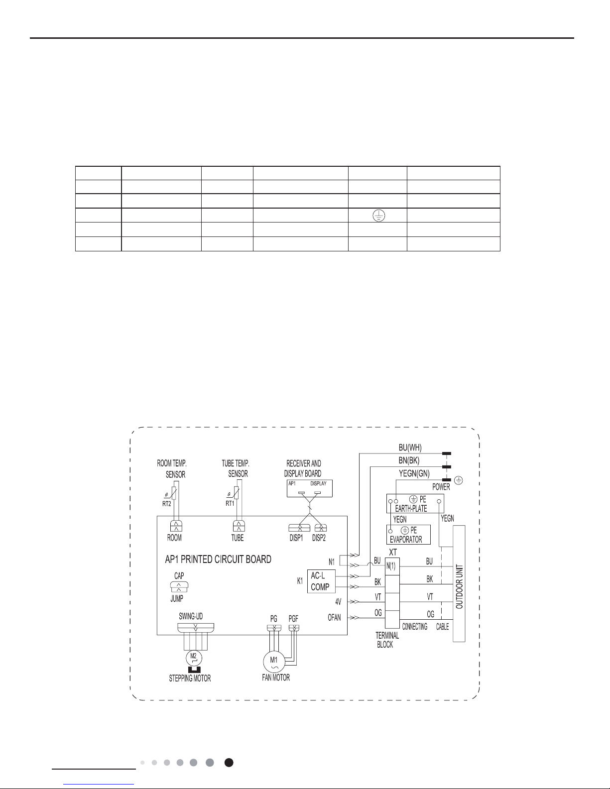
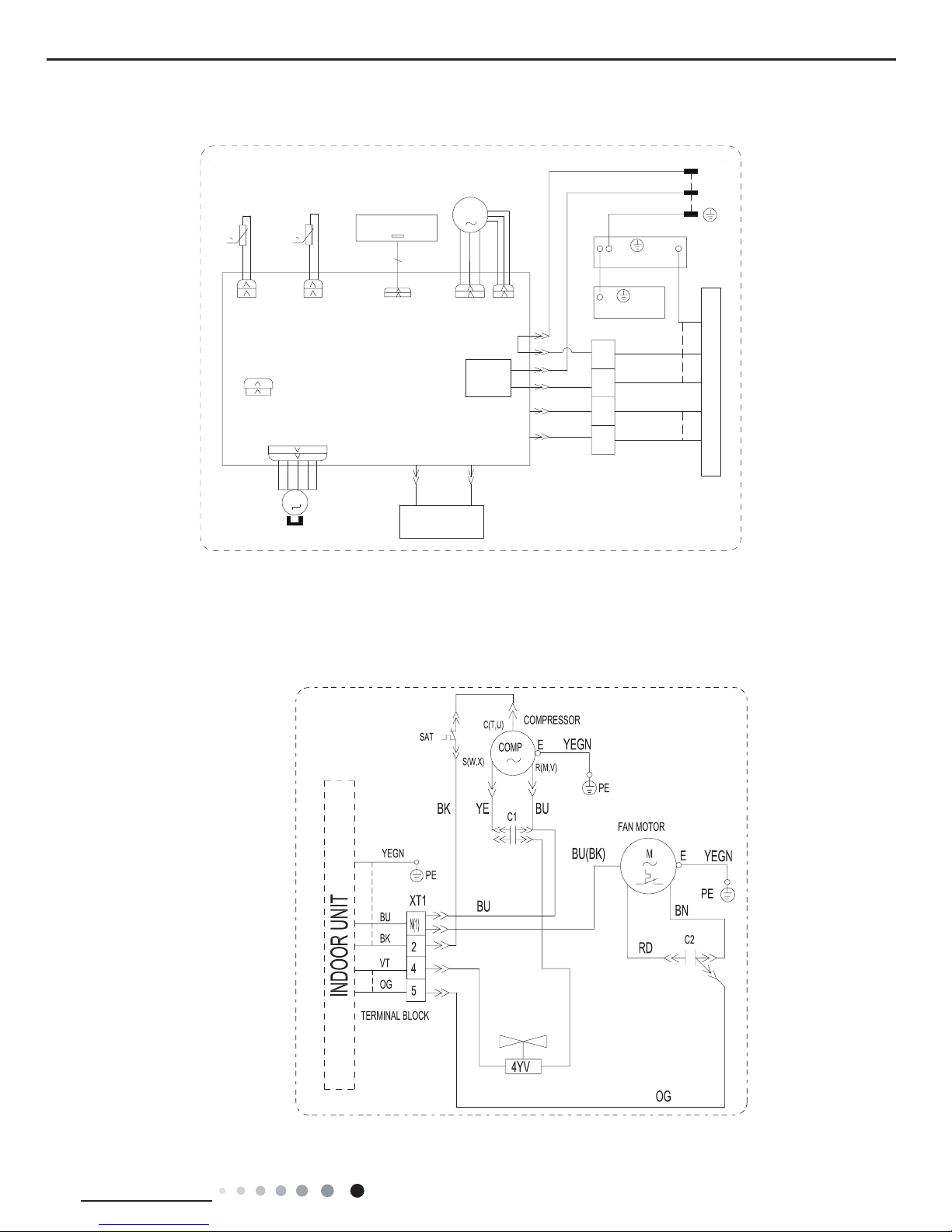
5.1 Wiring Diagram
● Indoor Unit
●Instruction
Symbol Symbol Color Symbol Symbol Color Symbol Name
WH White GN Green CAP Jumper cap
YE Yellow BN Brown COMP Compressor
RD Red BU Blue Grounding wire
YEGN Yellow/Green BK Black / /
VT Violet OG Orange / /
Note: Jumper cap is used to determine fan speed and the swing angle of horizontal lover for this model.
2
4
5
N
L
GWH07PA-K3NNA1F/I(CA414N02200) GWH09PA-K3NNA1F/I(CA414N02300) GWH07PA-K3NNA5F/I(CA417N01900)
GWH09PA-K3NNA5F/I(CA417N02000) GWH12PC-K3NNA1F/I(CA414N02400) GWH12PC-K3NNA5F/I(CA417N02100)
GWH09PA-K3NNA2F/I (CA415N03100) GWH09PB-K3NNA6E/I(CA430N00700) GWH12PC-K3NNA6E/I(CA430N00800)
GWH07PA-K3NNA6E/I(CA430N00600) GWH07PA-K3NNA5E/I(CA417N01600) GWH09PB-K3NNA5E/I(CA417N01700)
GWH12PC-K3NNA5E/I (CA417N01800) GWH07PA-K3NNA2E/I(CA415N01600) GWH09PB-K3NNA2E/I(CA415N01700)
GWH12PC-K3NNA2E/I(CA415N01800) GWH07PA-K3NNA7F/I(CA428N00600) GWH09PA-K3NNA7F/I(CA428N00700)
GWH12PC-K3NNA7F/I(CA428N00800) GWH07PA-K3NNA9E/I(CA429N00700) GWH09PB-K3NNA9E/I(CA429N00800)
GWH12PC-K3NNA9E/I(CA429N00900)
20
Technical Information
Service Manual
GWH07PA-K3NNA6E/I(CA430N00601) GWH09PB-K3NNA6E/I(CA430N00701) GWH12PC-K3NNA6E/I(CA430N00801)
GWH07PA-K3NNA2E/I(CA415N01601) GWH09PB-K3NNA2E/I(CA415N01701) GWH12PC-K3NNA2E/I(CA415N01801)
GWH07PA-K3NNA7F/I(CA428N00601) GWH09PA-K3NNA7F/I(CA428N00701) GWH07PA-K3NNA5E/I(CA417N01601)
GWH12PC-K3NNA5E/I(CA417N01801) GWH07PA-K3NNA9E/I(CA429N00701) GWH09PB-K3NNA9E/I(CA429N00801)
GWH12PC-K3NNA9E/I(CA429N00901) GWH07PA-K3NNA1F/I(CA414N02201) GWH09PA-K3NNA1F/I(CA414N02301)
GWH12PC-K3NNA1F/I(CA414N02401) GWH12PC-K3NNA7F/I(CA428N00801) GWH09PB-K3NNA5E/I(CA417N01701)
GWH07PA-K3NNA3E/I(CA416N01600) GWH09PB-K3NNA3E/I(CA416N01700) GWH12PC-K3NNA3E/I(CA416N01800)
2
4
5
N
L
FAN MOTOR
PGF
PG
M1
POWER
YEGN
YEGN(GN)
BN(BK)
BU(WH)
YEGN
EVAPORATOR
PE
PE
EARTH-PLATE
N1
BU
BK
XT
4V
OFAN
VT
OG
COMP
AC-L
K1
BU
BK
VT
OG
5
4
2
N(1)
M2
SWING-UD
OUTDOOR UNIT
CAP
JUMP
AP1 PRINTED CIRCUIT BOARD
ROOM
RT2
RT1
TUBE
SENSOR
SENSOR
ROOM TEMP.
TUBE TEMP.
STEPPING MOTOR
TERMINAL
BLOCK
C0NNECTING
CABLE
DISP1
AP1
DISPLAY BOARD
RECEIVER AND
0
0
L
N
21
Technical Information
Service Manual
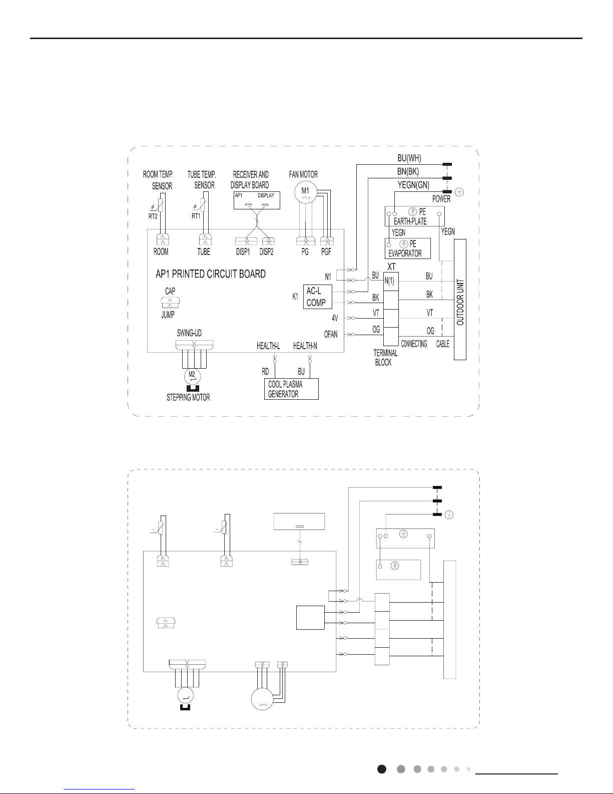
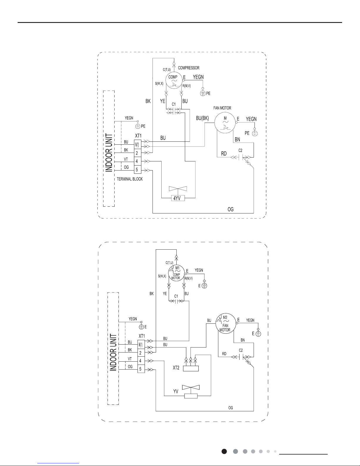
● Outdoor Unit
GWH07NA-K3NNE4E/O(CA403W01400) GWH07NA-K3NNC7F/O (CA195W06200)
GWH07PA-K3NNA3E/I(CA416N01601) GWH12PC-K3NNA3E/I(CA416N01801)
CABLE
C0NNECTING
GENERATOR
BLOCK
TERMINAL
STEPPING MOTOR
M1
FAN MOTOR
PG
PGF
TUBE TEMP.
ROOM TEMP.
SENSOR
SENSOR
TUBE
RT1
RT2
ROOM
AP1 PRINTED CIRCUIT BOARD
JUMP
CAP
OUTDOOR UNIT
SWING-UD
M2
HEALTH-L
HEALTH-N
BURD
COOL PLASMA
N(1)
2
4
5
OG
VT
BK
BU
K1
AC-L
COMP
OG
VT
OFAN
4V
XT
BK
BU
N1
EARTH-PLATE
PE
PE
EVAPORATOR
YEGN
BU(WH)
BN(BK)
YEGN(GN)
YEGN
POWER
RECEIVER AND
DISPLAY BOARD
AP1
DISP1
0
0
N
L
22
Technical Information
Service Manual
These wiring diagrams are subject to change without notice; please refer to the one supplied with the unit.
GWH12NC-K3NNE4E/O(CA403W01600) GWH12NC-K3NNC7F/O(CA195W06400)
GWH09MA-K3NNE4E/O(CA403W01500) GWH09NA-K3NNC7F/O(CA195W06300)
23
Technical Information
Service Manual
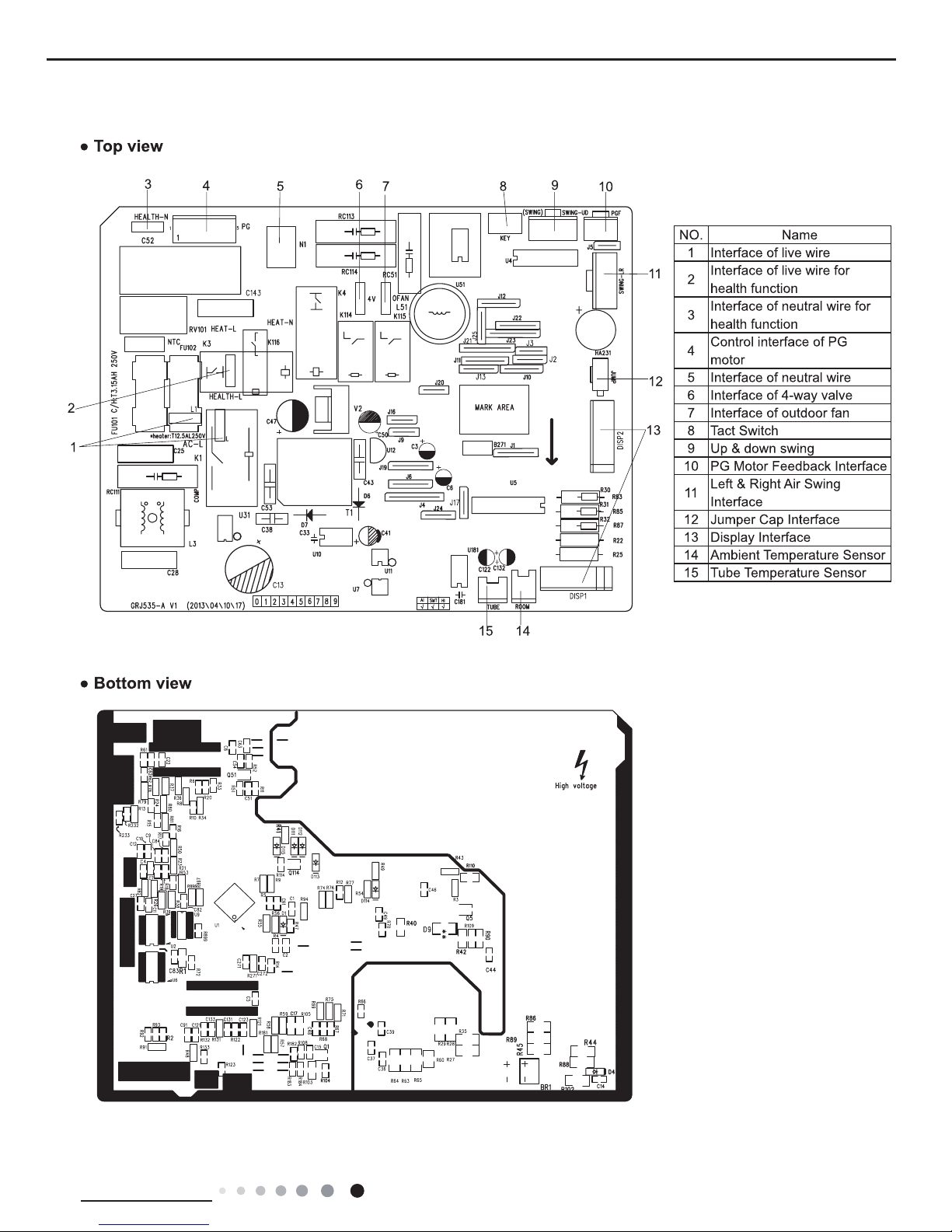
5.2 PCB Printed Diagram
24
Technical Information
Service Manual
6. Function and Control
6.1 Remote Controller Introduction of YX1F
AUTO
COOL
DRY
FAN
HEAT
T-ON T-OFF
SWING
SLEEP
LOCK
SPEED
+
_
ON/OFF
FAN SWING
SLEEP
TIMER
MODE
ON/OFF button
MODE button
+/- botton
FAN button
SWING button
SLEEP button
TIMER button
Icon Display on Remote
Controller
Operation introduction of remote controll
er
For auto operation
Timer on Timer off
Sending signal
For air swing
For sleeping
For locking
For setting fan speed
Set temperature
Set time
For cooling
For drying
For fan only
For heating
AUTO
COOL
DRY
FAN
HEAT
T-ON T-OFF
SWING
SLEEP
LOCK
SPEED
Buttons on Remote Controller
Note:
When power is connected(stand by condition), you can operate the air conditioner through the remote controller.
When unit is on, each time you press the button on remote controller, the sending signal icon on the display of remote controller
will blink once. If the air conditioner gives out a beep sound, it means the signal has been sent.
When unit is off, set temperature will be displayed on the remote controller(If the light of indoor unit display is turned on, the
corresponding icon will be displayed); When unit is on, it will display the icon of the on-going function.
1. ON/OFF Button
Press this button to turn unit on/of
f.
2. MODE Button
Pressing this button once can select your required mode circularly as below(the corresponding icon
will be lit up after the mode is
selected):
AUTO COOL DRYFAN HEAT
25
Technical Information
Service Manual
When selecting auto mode, air conditioner will operate automatically according to ex-factory setting. Set temperature can't be
adjusted and won't be displayed either
. Press FAN button to adjust fan speed. (This function is not available in this air conditioner.)
When selecting cool mode, air conditioner will operate under cool mode. Then press + or -- button to adjust set temperature. Press
FA
N button to adjust fan speed.
When selecting dry mode, air conditioner will operate at low fan speed under dry mode. In dry mode, fan speed can't be adjusted.
When selecting fan mode, air conditioner will operate in fan mode only. Then press FAN button to adjust fan speed.
When selecting heat mode, air conditioner will operate under heat mode. Then press + or -- button to adjust set temperature. Pr
ess
FA
N button to adjust fan speed.
3. +/- butto
n
Pressing + or - button once will increase or decrease set temperature by 1 °F(°C). Hold + or -- button for 2s, set temperature on
remote controller will change quickl
y. Release the button after your required set temperature is reached.
When setting Timer On, Timer Off or Clock, press + or -- button to adjust the time (See TIMER Button for setting details).
4.
FAN Button
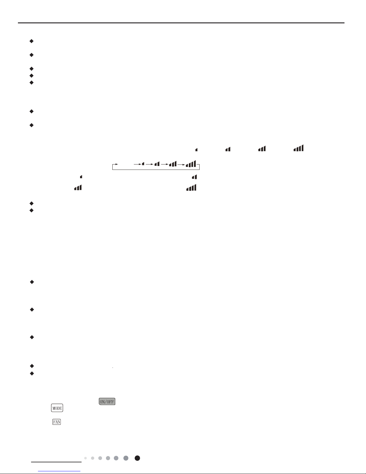
Pressing this button can select fan speed circularly as:
AUTO, SPEED 1( ), SPEED 2( ), SPEED 3( ), SPEED 4( ) (unavailable
in this air conditioner. Speed 4 is the same with speed 3).
Note:
Under Auto mode, air conditioner will select proper fan speed automatically according to ex-factory setting.
Fan speed can't be adjusted under Dry mode.
5. SWING Butto
n
Press this button to turn on up&down air swing.
6. SLEEP
Button
Under Cool, Heat, Dry mode, press this button to turn on Sleep function. Press this button to cancel Sleep function. Under Fan
and
A
uto mode, this function is unavailable.
Simple operationfi
rst
1.After putting through power
“
” button on remote controller to turn on the air conditioner.
2.Press “
” button to select your required operation mode: AUTO, COOL, DRY, FA N.
3.Press “+” or “-” button to set your required temperature.(temperature can’t adjusted under AUTO mode)
4.Press “
” button to select your required fan speed: auto, fi rst notch, second notch, third notch, fourth notch (fourthnotch is same
as third notch for this air conditioner.)
SPEED 2 (equals to medium fan speed)SPEED 1 (equals to low fan speed)
SPEED 3 (equals to high fan speed) SPEED 4
AUTO
7. TIMER Button
When unit is on, press this button to set Timer Off. T-OFF and H icon will be blinking. Within 5s, press + or - button to adjust the
When unit is off, press this button to set Timer On. T-ON and H icon will be blinking. Within 5s, press + or - button to adjust the
time for Timer On. Pressing + or - button once will increase or decrease the time by 0.5h. Hold + or - button for 2s, time will change
quickly. Release the button after your required set time is reached. Then press TIMER button to confirm it. T-ON and H icon will stop
blinking.
Cancel Timer On/Off: If Timer function is set up, press TIMER button once to review the remaining time. Within 5s, press TIMER
Note:
Range of time setting is: 0.5~24h
button again to cancel this function.
The interval between two motions can't exceed 5s, otherwise the remote controller will exit setting status.
time for Timer Off. Pressing + or - button once will increase or decrease the time by 0.5h. Hold + or - button for 2s, time will change
quickly. Release the button after your required set time is reached. Then press TIMER button to confirm it. T-OFF and H icon will
stop blinking.
26
Technical Information
Service Manual
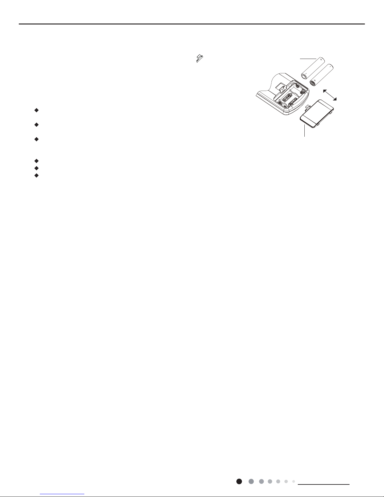
1. Press the back side of remote controller on the spot marked with
, and then
push out the cover of battery box along the arrow direction.
2. Replace two No.7 (AAA
1.5V) dry batteries and make sure the positions of + and --
polar are correct
.
3. Reinstall the cover of battery box.
Note:
During operation, point the signal sender of the remote controller at the receiving
window of the indoor unit;
The distance between signal sender and receiving window should be within 8m.
There should be no obstacle between them.
Signal may be interfered easily in the room where there is fl uorescent lamp
or wireless telephone; Remote controller should be close to indoor unit during
operation.
Replace new batteries of the same model when replacement is required.
If you don't use remote controller for a long time, please take out the batteries.
If the display on remote controller is fuzzy or if there's no display, please replace
batteries.
battery
cover of battery box
remove
reinstall
Replacement of Batteries in Remote Controller
27
Technical Information
Service Manual
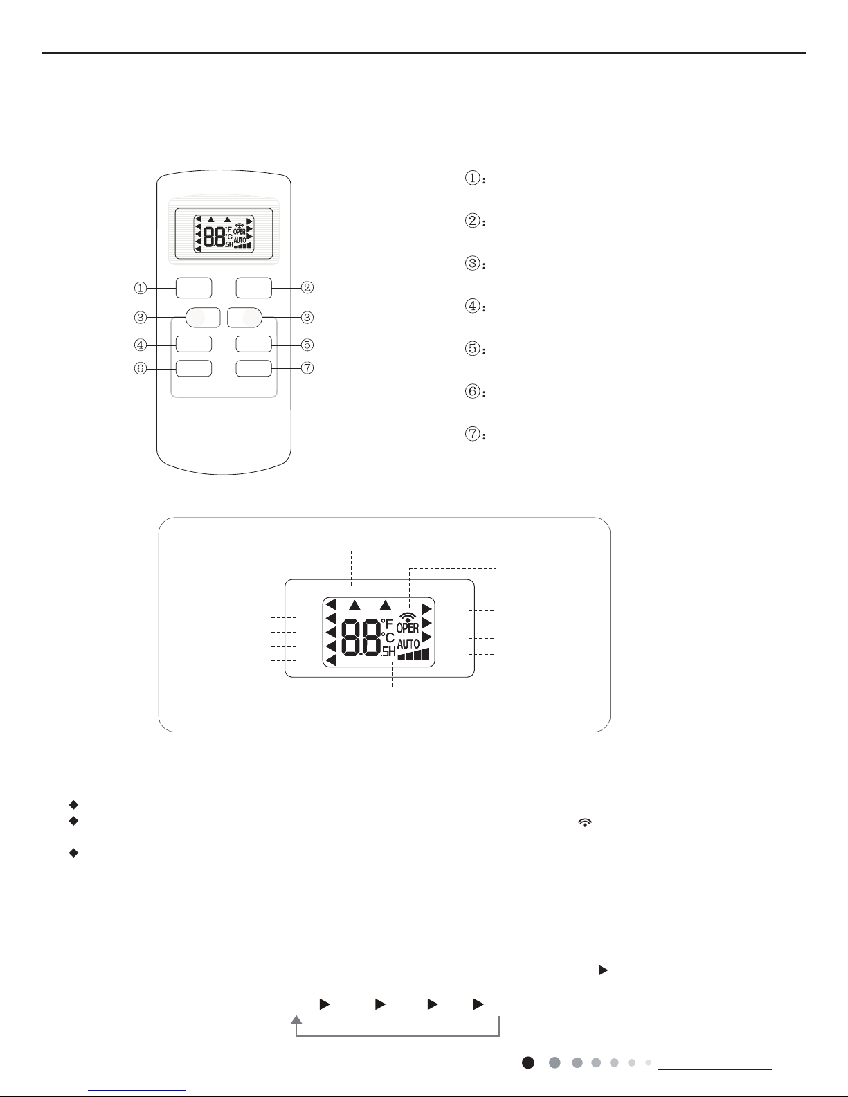
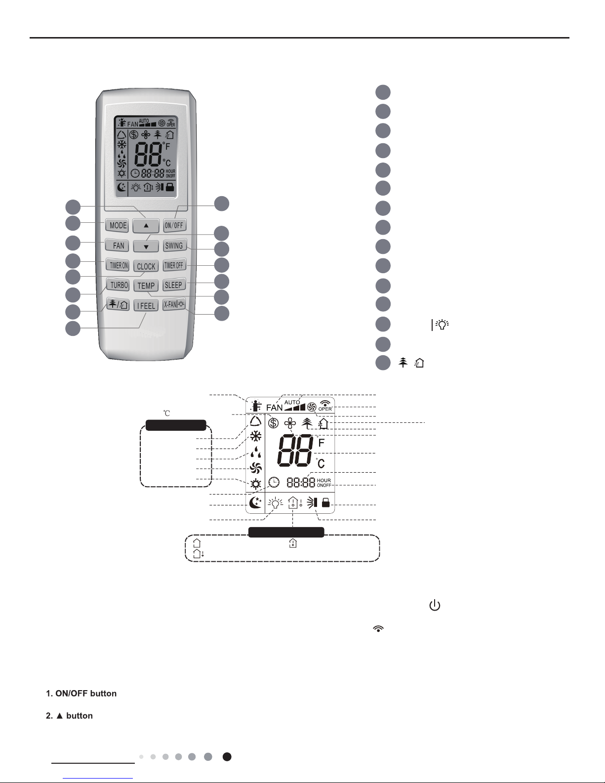
6.2 Remote Controller Introduction of YV1F7
Buttons on remote controller
Introduction for icons on display screen
1
14
3
1
13
2
2
5
4
6
7
8
11
12
13
9
14
15
ON/OFF button
▲ button
3
FAN button
SWING button
TIMER OFF button
TURBO button
10
TEMP button
I FEEL button
button
CLOCK button
TIMER ON button
SLEEP button
Send signal
Turbo mode
8
heating function
Set temperature
Set time
TIMER ON /
TIMER OFF
Child lock
Up & down swing
Set fan speed
ventilation operation
Light
Temp. display type
:Set temp.
:Outdoor ambient temp.
:Indoor ambient temp.
Sleep mode
Clock
Heat mode
Fan mode
Dry mode
Cool mode
Auto mode
Operation mode
I feel
6
9
8
12
15
4
7
10
5
11
X-FAN button
/
MODE button
▲
button
X-fan mode
health function
Introduction for buttons on remote controller
Note:
● After putting through the power, the air conditioner will give out a sound. Operation indictor " " is ON (red indicator).
After that, you can operate the air conditioner by using remote controller.
●
Under on status, pressing the button on the remote controller, the signal icon " "
on the display of remote controller
will blink once and the air conditioner will give out a “de” sound, which means the signal has been sent to the air conditioner
.
● Under off status, set temperature and clock icon will be displayed on the display
of remote controller (If timer on, timer
off and light functions are set, the corre-
sponding icons will be displayed on the display of remote controller at the same
time); Under on status, the display will show the corresponding set function icons.
Press this button to turn on the unit. Press this button again to turn off the unit.
Press this button to increase set temperature. Holding it down above 2 seconds rapidly increases set temperature.
In AUTO mode, set temperature is not adjustable.
 Loading...