

Gree GWH07NA-K3NNA8E, GWH07NA-K3NNE4E/I, GWH07NA-K3NNA8E/I, GWH07NA-K3NNA4E, GWH07NA-K3NNA4E/I Service Manual
...
Change for Life
Service Manual
GREE ELECTRIC APPLIANCES,INC.OF ZHUHAI

Table of Contents
Service Manual
Part
1.Summary
2. Specications
2.1 Specication Sheet ...........................................................................................................3
2.2 Capacity Curve in Different Outdoor Temperature ...........................................................7
2.3 Cooling and Heating Data Sheet in Rated Frequency .....................................................7
: Technical Information
Ⅰ
.......................................................................................................................1
..........................................................................................................3
3. Outline Dimension Diagram
3.1 Indoor Unit ........................................................................................................................8
3.2 Outdoor Unit .....................................................................................................................9
4. Refrigerant System Diagram
5. Electrical Part
5.1 Wiring Diagram ...............................................................................................................11
5.2 PCB Printed Diagram .....................................................................................................13
6. Function and Control
.........................................................................................................11
......................................................................................14
.......................................................................1
........................................................................8
....................................................................10
6.1 Remote Controller Introduction of YX1F .......................................................................14
6.2 Remote Controller Introduction of YB1F2(XFAN) ........................................................... 17
6.3 Brief Description of Modes and Functions ......................................................................21
Part
: Installation and Maintenance
Ⅱ
7. Notes for Installation and Maintenance
8. Installation
8.1 Installation Dimension Diagram ......................................................................................28
8.2 Installation Parts-Checking ............................................................................................30
8.3 Selection of Installation Location ....................................................................................30
8.4 Electric Connection Requirement ...................................................................................30
8.5 Installation of Indoor Unit ................................................................................................30
8.6 Installation of Outdoor unit .............................................................................................33
8.7 Vacuum Pumping and Leak Detection ...........................................................................34
8.8 Check after Installation and Test operation ....................................................................34
................................................................................................................28
.................................................26
..........................................26
Table of Contents

Service Manual
9. Maintenance
9.1 Error code .......................................................................................................................35
9.2 Procedure of Troubleshooting ........................................................................................36
9.3 Maintenance method for normal malfunction .................................................................41
10. Exploded View and Parts List
10.1 Indoor Unit ....................................................................................................................43
10.2 Outdoor Unit .................................................................................................................54
11. Removal Procedure
11.1 Removal Procedure of Indoor Unit ...............................................................................56
11.2 Removal Procedure of Outdoor Unit ............................................................................61
Appendix:
Appendix 1: Reference Sheet of Celsius and Fahrenheit ....................................................66
Appendix 2: Conguration of Connection Pipe .....................................................................66
Appendix 2: Pipe Expanding Method ...................................................................................67
........................................................................................................................66
............................................................................................................35
..............................................................43
.......................................................................................56
Appendix 4: List of Resistance for Temperature Sensor ......................................................68
Table of Contents
Service Manual
Part
Ⅰ
: Technical Information
1.Summary
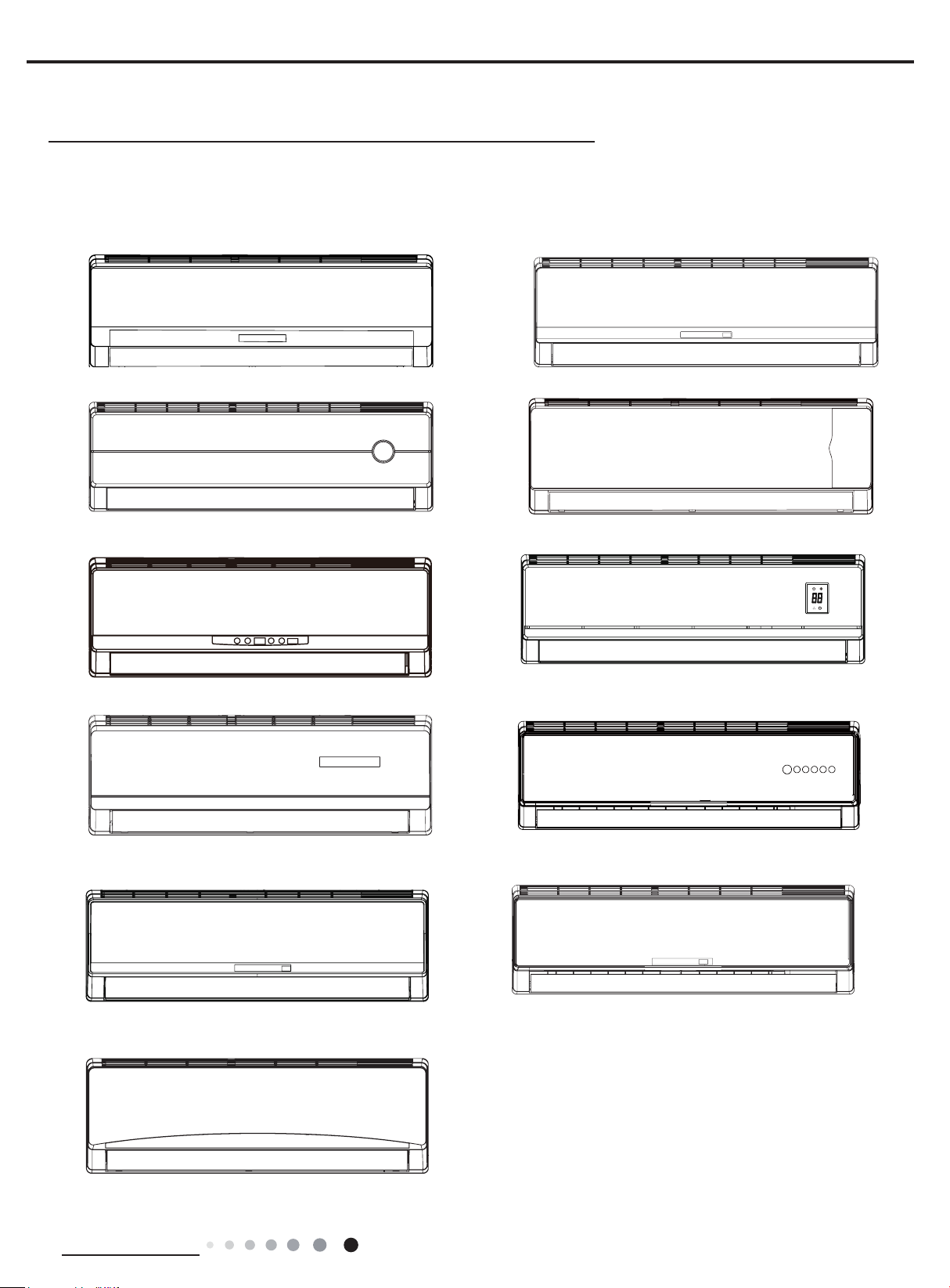
Indoor Unit:
A4
A8
B5
A5
B3
D2 (panel A)
D2 (panel C)
C7
E4
D1
E1
Technical Information
1
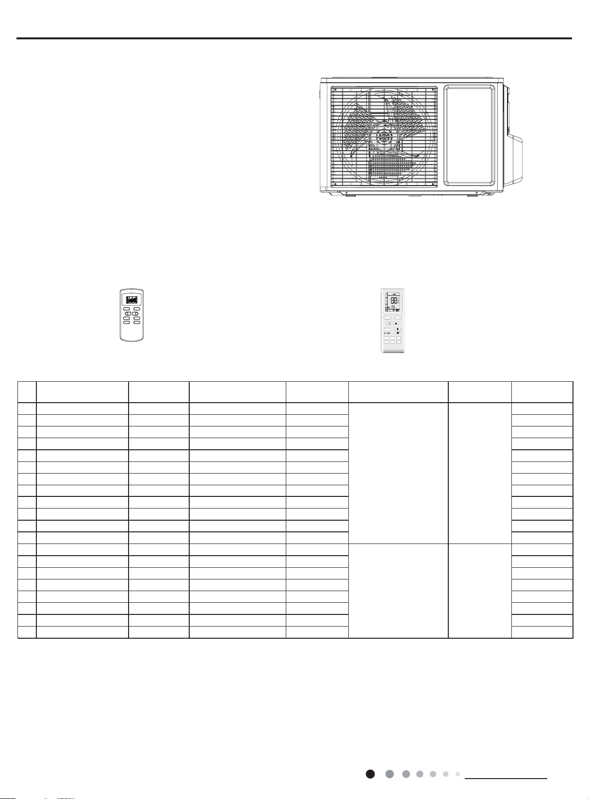
Outdoor Unit:
GWH07NA-K3NNC7F/O
GWH07NA-K3NNE4E/O
Remote Controller:
YX1F YB1F2(XFAN)
AUTO
FAN
T-ONT-OFF
AUTO
COOL
DRY
FAN
HEAT
ON/OFF MODE
-
FAN SWING
SLEEP TIMER
SWING
SLEEP
LOCK
SPEED
+
OPER
HEALTH
X-FAN
AIR
HUMIDITY
FILTER
TURBO
HOUR
ON/OFF
MODE
ON/OFF
FAN
X-FAN
TEMP
TIMER
LIGHT
SLEEP
TURBO
Service Manual
Model List:
NO. Unit model Unit code
Indoor unit
model
1 GWH07NA-K3NNE4E CA403001401 GWH07NA-K3NNE4E/I CA403N01400
Indoor unit
code
Outdoor unit
model
Outdoor unit
code
Remove
Controller
YX1F
2 GWH07NA-K3NND2E CA149000603 GWH07NA-K3NND2E/I CA149N00601 YX1F
3 GWH07NA-K3NNB3E CA138007301 GWH07NA-K3NNB3E/I CA138N07300 YX1F
4 GWH07NA-K3NNA8E CA173019301 GWH07NA-K3NNA8E/I CA173N19300 YX1F
5 GWH07NA-K3NNA4E CA161013002 GWH07NA-K3NNA4E/I CA161N13002 YX1F
6 GWH07NA-K3NNA4E CA161013001 GWH07NA-K3NNA4E/I CA161N13000 YX1F
7 GWH07NA-K3NND1E CA147004802 GWH07NA-K3NND1E/I CA147N04801 YX1F
GWH07NA-K3NNE4E/O CA403W01401
8 GWH07NA-K3NND2E CA149000604 GWH07NA-K3NND2E/I CA149N00602 YX1F
9 GWH07NA-K3NNB5E CA180010101 GWH07NA-K3NNB5E/I CA180N10100 YX1F
10
GWH07NA-K3NNA5E
CA162020601 GWH07NA-K3NNA5E/I
CA162N20600 YX1F
11 GWH07NA-K3NNE1E CA404007301 GWH07NA-K3NNE1E/I CA404N07300 YX1F
12 GWH07NA-K3NNC7E CA195007501 GWH07NA-K3NNC7E/I CA195N07500 YX1F
13 GWH07NA-K3NNC7F CA195006202 GWH07NA-K3NNC7F/I CA195N06200
YX1F
14 GWH07NA-K3NNB3F CA138007501 GWH07NA-K3NNB3F/I CA138N07500 YX1F
15 GWH07NA-K3NND1F CA147005101 GWH07NA-K3NND1F/I CA147N05100 YX1F
16 GWH07NA-K3NND2F CA149000803 GWH07NA-K3NND2F/I CA149N00800 YB1F2(XFAN)
17 GWH07NA-K3NND2F CA149000802 GWH07NA-K3NND2F/I CA149N00801 YB1F2(XFAN)
GWH07NA-K3NNC7F/O CA195W06200
18 GWH07NA-K3NNC7F CA195006203 GWH07NA-K3NNC7F/I CA195N06201 YB1F2(XFAN)
19 GWH07NA-K3NNE1F CA404006902 GWH07NA-K3NNE1F/I CA404N06900 YB1F2(XFAN)
20 GWH07NA-K3NNE1F CA404006903 GWH07NA-K3NNE1F/I CA404N06901 YB1F2(XFAN)
2
Technical Information
Service Manual
2. Specications
2.1 Specication Sheet
1.GWH07NA-K3NNC7F 2.GWH07NA-K3NNB3F
Model
Product Code
Power
Supply
Power Supply Mode Indoor
Cooling Capacity W 2200
Heating Capacity W 2200
Cooling Power Input W 783
Heating Power Input W 650
Cooling Power Current A 3.47
Heating Power Current A 3.0
Rated Input W 1100
Rated Current A 4.9
Air Flow Volume(SH/H/M/L/SL) m3/h 400/360/320/290/-
Dehumidifying Volume L/h 0.6
EER W/W 2.81
COP W/W 3.38
SEER W/W /
HSPF W/W /
Application Area m
Indoor Unit
Rated Voltage V~ 220-240
Rated Frequency Hz 50
Phases 1
2
Model of Indoor Unit
Product Code of Indoor Unit
Fan Type Cross-ow
Diameter Length(DXL) mm Φ85X532
Fan Motor Cooling Speed(SH/H/M/L/SL) r/min 1390/1280/1180/1080/-
Fan Motor Heating Speed(SH/H/M/L/SL) r/min 1350/1250/1140/1040/Output of Fan Motor W 10
Fan Motor RLA A 0.15
Fan Motor Capacitor μF 1
Input of Heater W /
Evaporator Form Aluminum Fin-copper Tube
Pipe Diameter mm Φ7
Row-n Gap mm 2-1.5
Coil Length (LXDXW) mm 526X25.4X228.6
Swing Motor Model MP24AA
Output of Swing Motor W 1.5
Fuse A 3.15
Sound Pressure Level (SH/H/M/L/SL) dB (A) 37/34/31/28/-
Sound Power Level (SH/H/M/L/SL) dB (A) 47/44/41/38/-
Dimension (WXHXD) mm 730X254X170
Dimension of Carton Box (LXWXH) mm 784X311X236
Dimension of Package (LXWXH) mm 787X314X251
Net Weight kg 8
Gross Weight kg 9.5
3.GWH07NA-K3NND1F 4.GWH07NA-K3NND2F
5.GWH07NA-K3NNE1F
1.CA195006202 CA195006203 2.CA138007501
3.CA147005101 4.CA149000803 CA149000802
5.CA404006902 CA404006903
1.GWH07NA-K3NNC7F/I 2.GWH07NA-K3NNB3F/I
3.GWH07NA-K3NND1F/I 4.GWH07NA-K3NND2F/I
5.GWH07NA-K3NNE1F/I
1.CA195N06200 CA195N06201 2. CA138N07500
3.CA147N05100 4. CA149N00800 CA149N00801
5.CA404N06900 CA404N06901
10-16
Technical Information
3
Outdoor Unit
Connection
Pipe
Model of Outdoor Unit GWH07NA-K3NNC7F/O
Product Code of Outdoor Unit CA195W06201
Compressor Manufacturer/Trademark ZHUHAI LANDA COMPRESSOR CO. LTD.
Compressor Model QXA-A081A130
Compressor Oil RB68EP
Compressor Type Rotary
L.R.A. A 15
Compressor RLA A 3.3
Compressor Power Input W 685
Overload Protector Internal
Throttling Method Capillary
Operation Temp
Ambient Temp (Cooling)
Ambient Temp (Heating)
o
C 16~30
o
C 18~43
o
C -10~24
Condenser Form Aluminum Fin-copper Tube
Pipe Diameter mm Φ7
Rows-n Gap mm 1-1.4
Coil Length (LXDXW)
mm
474X12.7X400
Fan Motor Speed rpm 950
Output of Fan Motor W 20
Fan Motor RLA
A 0.25
Fan Motor Capacitor μF 1.5
Air Flow Volume of Outdoor Unit m3/h 1200
Fan Type Axial-ow
Fan Diameter mm Φ320
Defrosting Method Automatic Defrosting
Climate Type T1
Isolation I
Moisture Protection IPX4
Permissible Excessive Operating Pressure for
the Discharge Side
Permissible Excessive Operating Pressure for
the Suction Side
MPa 4.3
MPa 2.5
Sound Pressure Level (H/M/L) dB (A) 50/-/-
Sound Power Level (H/M/L) dB (A) 60/-/-
Dimension (WXHXD) mm 720X428X310
Dimension of Carton Box (LXWXH) mm 765X350X475
Dimension of Package (LXWXH) mm 768X353X490
Net Weight kg 22
Gross Weight kg 24
Refrigerant R410A
Refrigerant Charge kg 0.5
Length m 5
Gas Additional Charge g/m 20
Outer Diameter Liquid Pipe mm Φ6
Outer Diameter Gas Pipe mm Φ9.52
Max Distance Height m 10
Max Distance Length m 15
Note: The connection pipe applies metric diameter.
Service Manual
The above data is subject to change without notice; please refer to the nameplate of the unit.
4
Technical Information
Service Manual
1.GWH07NA-K3NNE4E 2.GWH07NA-K3NND2E
3.GWH07NA-K3NNB3E 4.GWH07NA-K3NNA8E
Model
5.GWH07NA-K3NNA4E 6.GWH07NA-K3NND1E
7.GWH07NA-K3NND2E 8.GWH07NA-K3NNB5E
9.GWH07NA-K3NNA5E 10.GWH07NA-K3NNE1E
11.GWH07NA-K3NNC7E
1.CA403001401 2.CA149000603
3.CA138007301 4.CA173019301
Product Code
5.CA161013002 CA161013001 6.CA147004802
7.CA149000604 8.CA180010101
9.CA162020601 10.CA404007301
11.CA195007501
Power
Supply
Rated Voltage V~ 220-240
Rated Frequency Hz 50
Phases 1
Power Supply Mode Indoor
Cooling Capacity W 2250
Heating Capacity W 2300
Cooling Power Input W 700
Heating Power Input W 637
Cooling Power Current A 3.10
Heating Power Current A 2.92
Rated Input W 1050
Rated Current A 4.8
Air Flow Volume(SH/H/M/L/SL) m3/h 400/360/320/290/Dehumidifying Volume L/h 0.6
EER W/W 3.21
COP W/W 3.61
SEER W/W /
HSPF W/W /
Application Area m
2
10-16
1.GWH07NA-K3NNE4E/I 2.GWH07NA-K3NND2E/I
3.GWH07NA-K3NNB3E/I 4.GWH07NA-K3NNA8E/I
Model of Indoor Unit
5.GWH07NA-K3NNA4E/I 6.GWH07NA-K3NND1E/I
7.GWH07NA-K3NND2E/I 8.GWH07NA-K3NNB5E/I
9.GWH07NA-K3NNA5E/I 10.GWH07NA-K3NNE1E/I
11.GWH07NA-K3NNC7E/I
1.CA403N01400 2.CA149N00601
3.CA138N07300 4.CA173N19300
Product Code of Indoor Unit
5.CA161N13002 CA161N13000 6.CA147N04801
7.CA149N00602 8.CA180N10100
9.CA162N20600 10.CA404N07300
11.CA195N07500
Fan Type Cross-ow
Diameter Length(DXL) mm Φ85X532
Fan Motor Cooling Speed(SH/H/M/L/SL) r/min 1390/1280/1180/1080/Fan Motor Heating Speed(SH/H/M/L/SL) r/min 1350/1250/1140/1040/Output of Fan Motor W 10
Indoor Unit
Fan Motor RLA A 0.15
Fan Motor Capacitor μF 1
Input of Heater W /
Evaporator Form Aluminum Fin-copper Tube
Pipe Diameter mm Φ7
Row-n Gap mm 2-1.5
Coil Length (LXDXW) mm 526X25.4X228.6
Swing Motor Model MP24AA
Output of Swing Motor W 1.5
Fuse A 3.15
Sound Pressure Level (SH/H/M/L/SL) dB (A) 37/35/31/28/Sound Power Level (SH/H/M/L/SL) dB (A) 47/45/41/38/Dimension (WXHXD) mm 730X255X170
Dimension of Carton Box (LXWXH) mm 784X311X236
Dimension of Package (LXWXH) mm 787X314X251
Net Weight kg 8
Gross Weight kg 9.5
Technical Information
5
Outdoor Unit
Connection
Pipe
Model of Outdoor Unit GWH07NA-K3NNE4E/O
Product Code of Outdoor Unit CA403W01401
Compressor Manufacturer/Trademark ZHUHAI LANDA COMPRESSOR CO. LTD.
Compressor Model QXA-A081A130
Compressor Oil RB68EP
Compressor Type Rotary
L.R.A. A 15
Compressor RLA A 3.30
Compressor Power Input W 685
Overload Protector Internal
Throttling Method Capillary
Operation Temp
Ambient Temp (Cooling)
Ambient Temp (Heating)
o
C 16~30
o
C 18~43
o
C -10~24
Condenser Form Aluminum Fin-copper Tube
Pipe Diameter mm Φ7
Rows-n Gap mm 1-1.4
Coil Length (LXDXW) mm 658.3X19.05X396
Fan Motor Speed rpm 950
Output of Fan Motor W 20
Fan Motor RLA A 0.25
Fan Motor Capacitor μF 1.5
Air Flow Volume of Outdoor Unit m3/h 1200
Fan Type Axial-ow
Fan Diameter mm Φ320
Defrosting Method Automatic Defrosting
Climate Type T1
Isolation I
Moisture Protection IPX4
Permissible Excessive Operating Pressure for
the Discharge Side
Permissible Excessive Operating Pressure for
the Suction Side
MPa 4.3
MPa 2.5
Sound Pressure Level (H/M/L) dB (A) 48/-/-
Sound Power Level (H/M/L) dB (A) 58/-/-
Dimension (WXHXD) mm 720X428X310
Dimension of Carton Box (LXWXH) mm 765X350X475
Dimension of Package (LXWXH) mm 768X353X490
Net Weight kg 22.5
Gross Weight kg 24.5
Refrigerant R410A
Refrigerant Charge kg 0.6
Length m 5
Gas Additional Charge g/m 20
Outer Diameter Liquid Pipe mm Φ6
Outer Diameter Gas Pipe mm Φ9.52
Max Distance Height m 10
Max Distance Length m 15
Note: The connection pipe applies metric diameter.
Service Manual
The above data is subject to change without notice; please refer to the nameplate of the unit.
6
Technical Information
Service Manual
)
%
(
o i t a r y t i c a p a
C
24
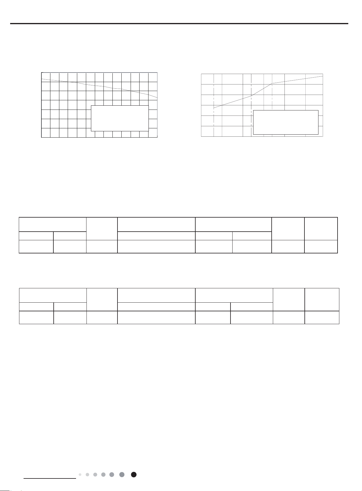
2.2 Capacity Curve in Different Outdoor Temperature
Cooling Heating
110
100
90
80
70
60
50
40
Condition
Indoor:DB27
Indoor air flow: Super High
Pipe length:5m
°C
WB19
°C
32 33 34 35 36 37 38 39 40 41 42 43 44 45
Outdoor temp.( ) Outdoor temp.( )
°C
120
)%(oitar yticapaC
100
80
60
40
20
0
-10510
2.3 Cooling and Heating Data Sheet in Rated Frequency
Cooling
Rated cooling condition(°C)
(DB/WB)
Indoor Outdoor P (MPa) T1 (°C) T2 (°C)
27/19 35/24 07K 0.85~1.0
Model
Pressure of gas pipe connecting
indoor and outdoor unit
Inlet and outlet pipe temperature
of heat exchanger
in:8~11
out:11~14
Condition Heating
Indoor:DB20
Indoor air flow: Super High
Pipe length:5m
°C
Fan speed of
indoor unit
in:75~85
out:37~43
Super High High
°C
157-7 -5 02
Fan speed of
outdoor unit
Heating
Rated heatling condition(°C)
(DB/WB)
Indoor Outdoor P (MPa) T1 (°C) T2 (°C)
20/- 7/6 07K 3.5~3.8
Instruction:
T1: Inlet and outlet pipe temperature of evaporator
T2: Inlet and outlet pipe temperature of condenser
P: Pressure at the side of big valve
Connection pipe length: 5 m.
Model
Pressure of gas pipe connecting
indoor and outdoor unit
Inlet and outlet pipe temperature
of heat exchanger
in:75~85
out:37~43
in:1~3
out:2~5
Fan speed of
indoor unit
Super High High
Fan speed of
outdoor unit
Technical Information
7
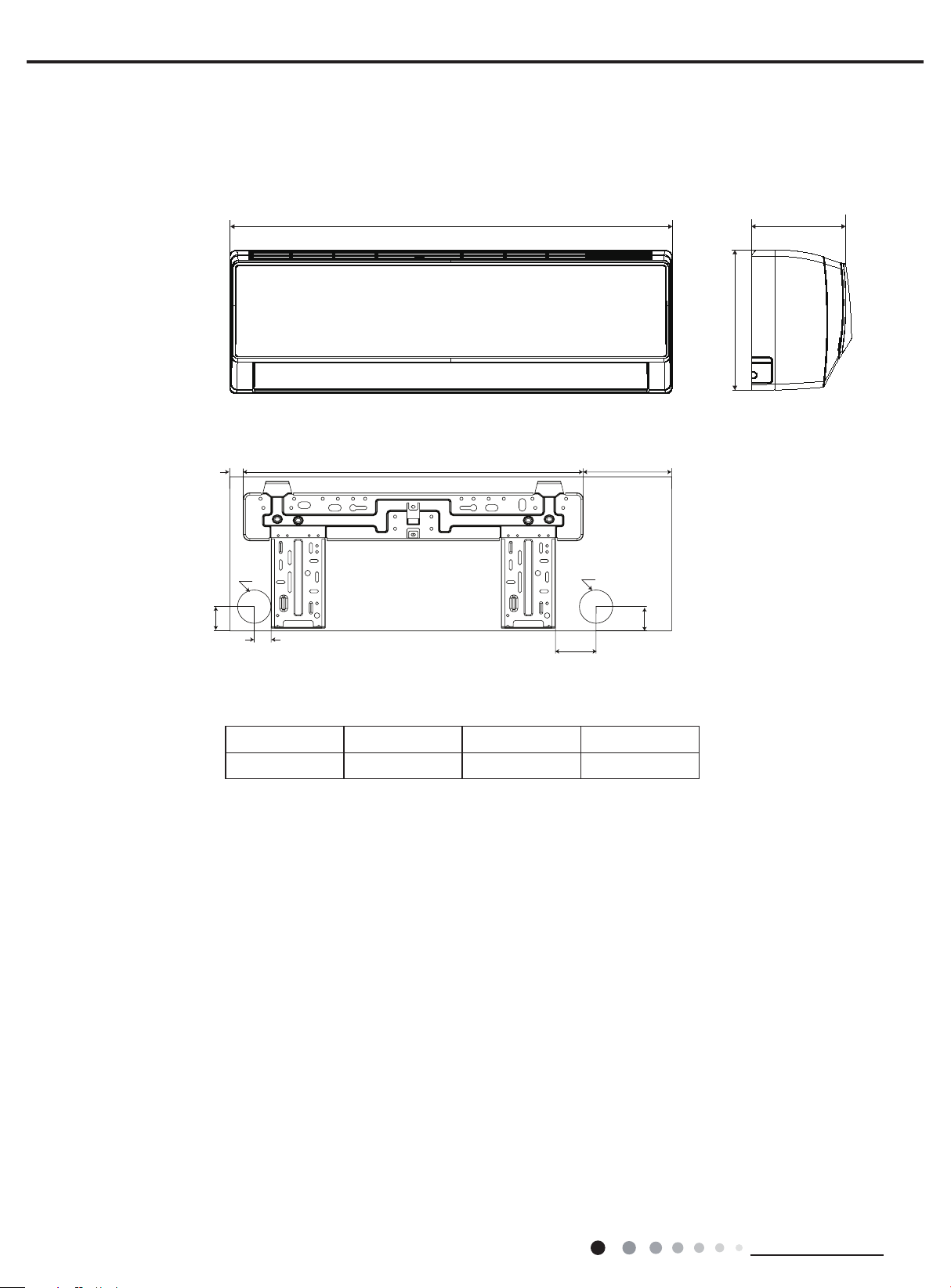
3. Outline Dimension Diagram
D
W
40
3.1 Indoor Unit
Service Manual
H
22
Φ55
562
25
Unit:mm
Model W H D
07K 730 255 170
65
Φ55
146
40
8
Technical Information
Service Manual
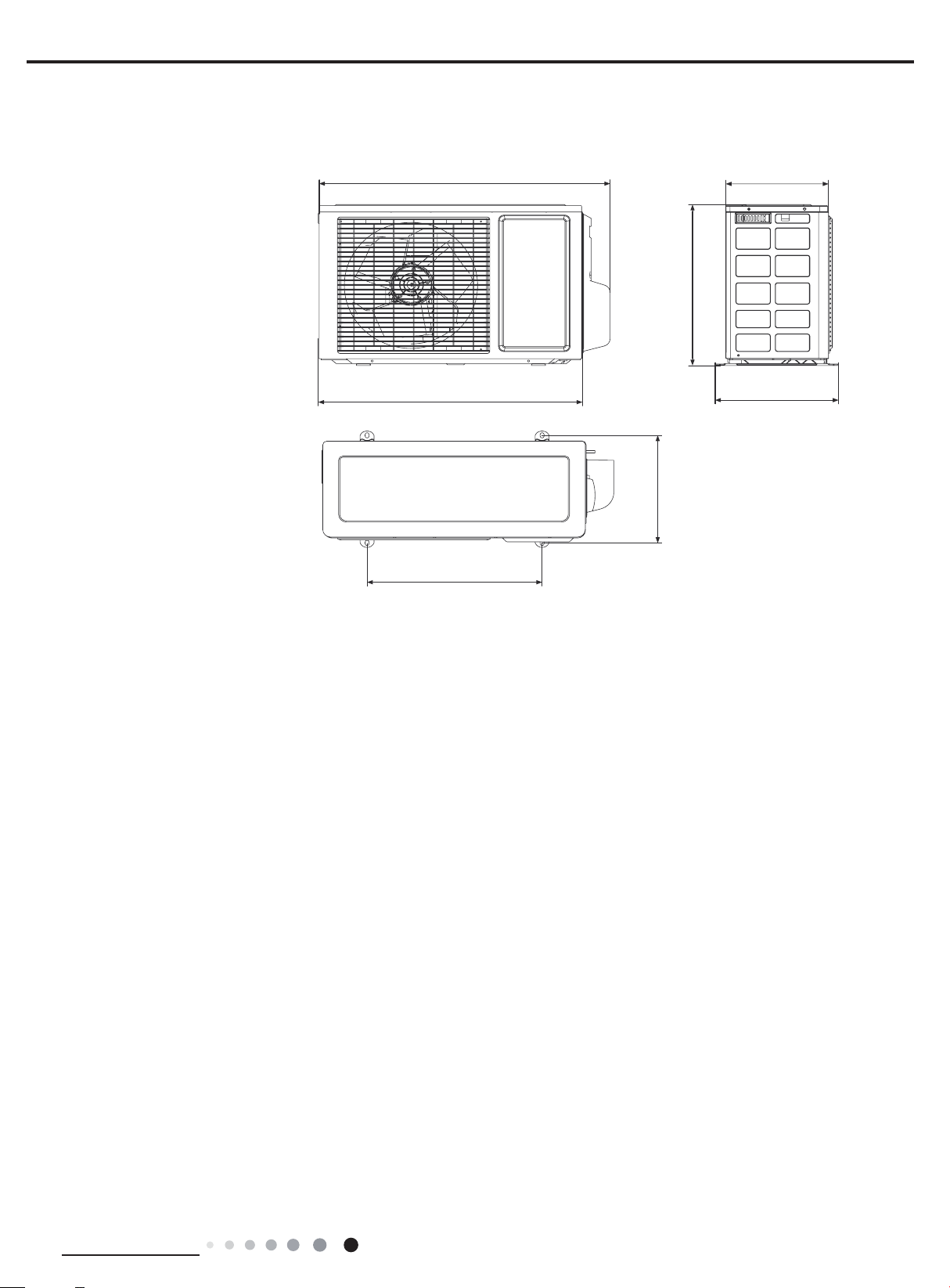
255
720
3.2 Outdoor Unit
GWH07NA-K3NNC7F/O
GWH07NA-K3NNE4E/O
428
660
440
310
286
Unit:mm
Technical Information
9
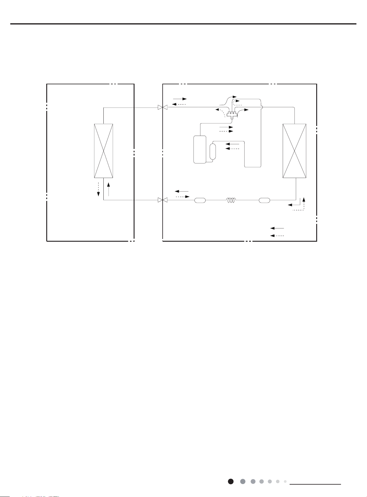
4. Refrigerant System Diagram
Indoor unit
Outdoor unit
Accumlator
COOLING
Discharge
Suction
Heat
exchanger
(evaporator)
Heat
exchanger
(condenser)
Valve
Valve
Liquid pipe
side
Gas pipe
side
Compressor
Strainer
Capillary
Cooling and heating model
Service Manual
Indoor unit
Heat
exchanger
(evaporator)
Connection pipe specication:
Liquid pipe:1/4" (6mm)
Gas pipe:3/8" (9.52mm)
Gas pipe
side
Valve
Liquid pipe
side
Valve
Outdoor unit
Discharge
Compressor
Strainer
Suction
Accumlator
4-Way valve
Heat
exchanger
(condenser)
StrainerCapillary
COOLING
HEATING
10
Technical Information
Service Manual
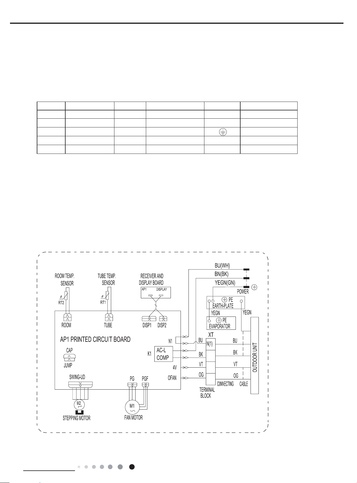
5. Electrical Part
5.1 Wiring Diagram
●Instruction
Symbol Symbol Color Symbol Symbol Color Symbol Name
WH White GN Green CAP Jumper cap
YE Yellow BN Brown COMP Compressor
RD Red BU Blue Grounding wire
YEGN Yellow/Green BK Black / /
VT Violet OG Orange / /
Note: Jumper cap is used to determine fan speed and the swing angle of horizontal lover for this model.
● Indoor Unit
GWH07NA-K3NNC7F/I(CA195N06200) GWH07NA-K3NNE4E/I GWH07NA-K3NNB3F/I GWH07NA-K3NND1F/I
GWH07NA-K3NND2F/I( CA149N00800) GWH07NA-K3NND2E/I GWH07NA-K3NNB3E/I GWH07NA-K3NNA8E/I
GWH07NA-K3NNA4E/I(CA161N13002) GWH07NA-K3NNE1E/I GWH07NA-K3NNC7E/I
N
L
2
Technical Information
4
5
63632164
11
Service Manual
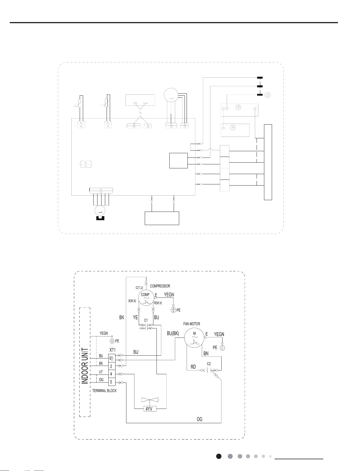
GWH07NA-K3NND2F/I(CA149N00801) GWH07NA-K3NNC7F/I(CA195N06201) GWH07NA-K3NNE1F/I(CA404N06900)
(CA404N06901) GWH07NA-K3NND1E/I GWH07NA-K3NND2E/I GWH07NA-K3NNB5E/I GWH07NA-K3NNA5E/I
GWH07NA-K3NNA4E/I(CA161N13000)
ROOM TEMP.
SENSOR
0
RT2
ROOM
TUBE TEMP.
SENSOR
0
RT1
TUBE
RECEIVER AND
DISPLAY BOARD
AP1
DISP1
AP1 PRINTED CIRCUIT BOARD
CAP
JUMP
SWING-UD
M2
STEPPING MOTOR
DISPLAY
DISP2
HEALTH-L
COOL PLASMA
GENERATOR
FAN MOTOR
M1
PG
AC-L
K1
COMP
HEALTH-N
BURD
PGF
N1
OFAN
4V
EVAPORATOR
XT
BU
N(1)
BK
2
VT
4
OG
5
TERMINAL
BLOCK
BU(WH)
BN(BK)
YEGN(GN)
PE
EARTH-PLATE
YEGN
PE
C0NNECTING
N
L
POWER
YEGN
BU
BK
VT
OUTDOOR UNIT
OG
CABLE
6363216402
● Outdoor Unit
GWH09NA-K3NNC7F/O GWH07NA-K3NNE4E/O
12
61413350
These wiring diagrams are subject to change without notice; please refer to the one supplied with the unit.
Technical Information
Service Manual
34 56 78
13
14
15
16
21
temperature
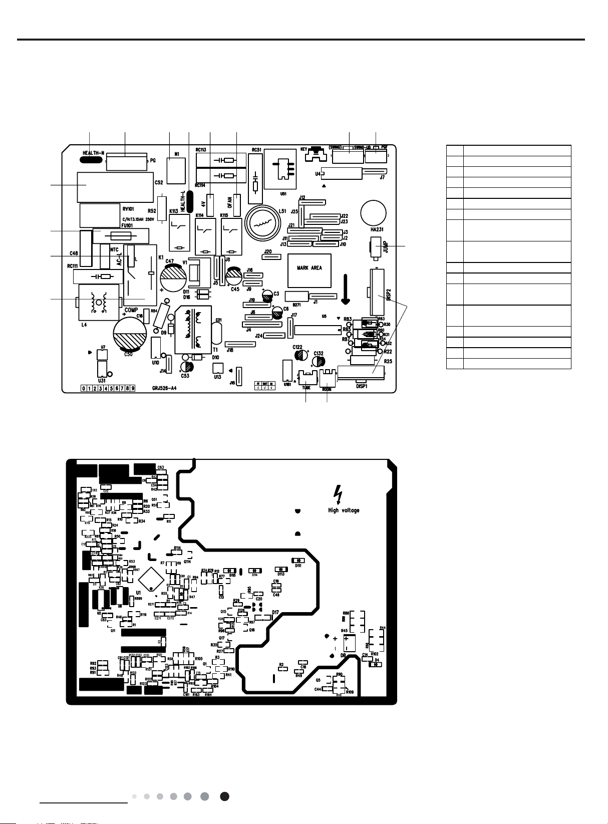
5.2 PCB Printed Diagram
● Top view
No. Name
1Neutral wire of cold plasma
2Terminal of PG Motor
3Neutral wire
4Live wire of cold plasma
54-way valve terminal
6Terminal of outdoor fan
Interface of up&down swing
7
9
10
motor
Feedback interface for PG
8
motor
9Jumper cap
10 Display interface
Interface of ambient
11
temperature sensor
Interface of pipe
12
sensor
13 Compressor control terminal
14 Live wire
15 Fuse
16 Capacitor for indoor fan
● Bottom view
1112
Technical Information
13
6. Function and Control
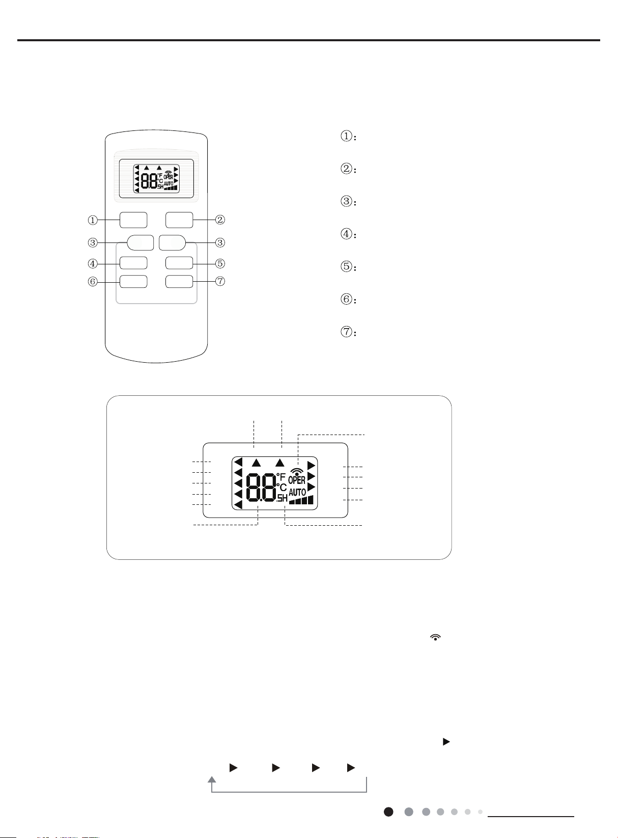
Icon Display on Remote Cont
Operation introduction of remote controll
Buttons on Remote Controller
1. ON/OFF Butto
Press this button to turn unit on/o
2. MODE Butto
Pressing this button once can select your required mode circularly as below(the corresponding icon
selected)
6.1 Remote Controller Introduction of YX1F
Service Manual
ON/OFF button
AUTO
COOL
DRY
FAN
HEAT
ON/OFF
T-ON T-OFF
_
FAN SWING
SLEEP
MODE
+
TIMER
SWING
SLEEP
LOCK
SPEED
MODE button
+/- botton
FAN button
SWING button
SLEEP button
TIMER button
roller
Timer on Timer off
Sending signal
For auto operation
For cooling
For drying
For fan only
For heating
Set temperature
AUTO
COOL
DRY
FAN
HEAT
T-ON T-OFF
SWING
SLEEP
LOCK
SPEED
For air swing
For sleeping
For locking
For setting fan speed
Set time
er
Note:
● This is a general use remote controller, it could be used for the air conditionerswith multifunction; For some function, which the
model doesn't have, if pressthe corresponding button on the remote controller that the unit will keep theoriginal running status.
● When power is connected(stand by condition), you can operate the air conditioner through the remote controller.
● When unit is on, each time you press the button on remote controller, the sending signal icon " " on the display of remote
controller will blink once. If the air conditioner gives out a beep sound, it means the signal has been sent.
● When unit is off, set temperature will be displayed on the remote controller (If the light of indoor unit display is turned on, the
corresponding icon will be displayed);When unit is on, it will display the icon of the on-going function.
n
ff.
n
:
AUTO COOL DRYFAN HEAT
14
will be lit up after the mode is
Technical Information
Service Manual
When selecting auto mode, air conditioner will operate automatically according to ex-factory setting. Set temperature can't be
adjusted and won't be displayed either
FA
ess
FA
3. +/- butto
remote controller will change quickl
4.
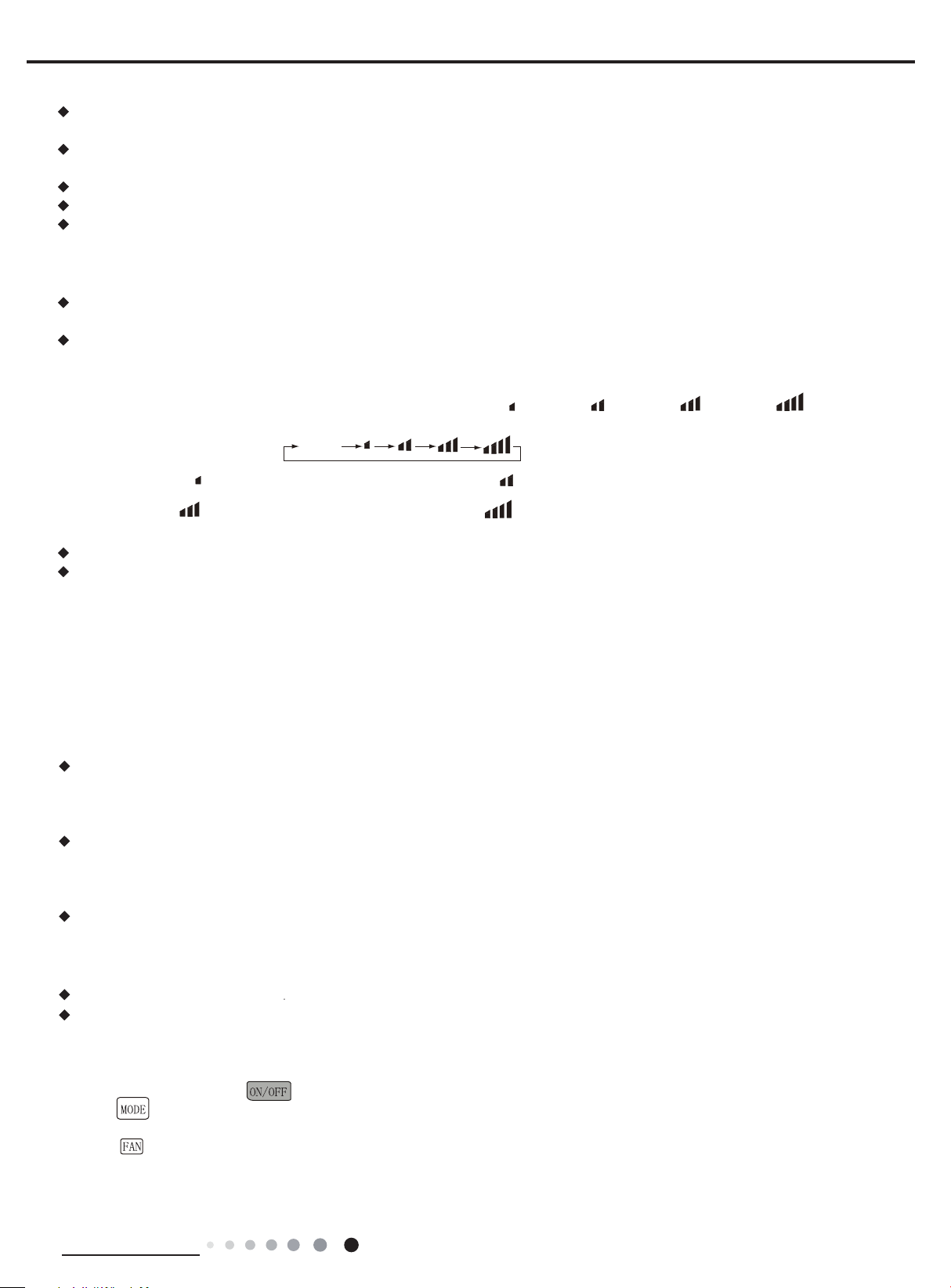
Pressing this button can select fan speed circularly as:
5. SWING Butto
Press this button to turn on up&down air swing.
6. SLEEP
Under Cool, Heat, Dry mode, press this button to turn on Sleep function. Press this button to cancel Sleep function. Under Fan
A
Simple operationfi
1.After putting through power
as third notch for this air conditioner.)
. Press FAN button to adjust fan speed. (This function is not available in this air conditioner.)
When selecting cool mode, air conditioner will operate under cool mode. Then press + or -- button to adjust set temperature. Press
N button to adjust fan speed.
When selecting dry mode, air conditioner will operate at low fan speed under dry mode. In dry mode, fan speed can't be adjusted.
When selecting fan mode, air conditioner will operate in fan mode only. Then press FAN button to adjust fan speed.
When selecting heat mode, air conditioner will operate under heat mode. Then press + or -- button to adjust set temperature. Pr
N button to adjust fan speed.
Pressing + or - button once will increase or decrease set temperature by 1 °F(°C). Hold + or -- button for 2s, set temperature on
When setting Timer On, Timer Off or Clock, press + or -- button to adjust the time (See TIMER Button for setting details).
FAN Button
in this air conditioner. Speed 4 is the same with speed 3).
Note:
Under Auto mode, air conditioner will select proper fan speed automatically according to ex-factory setting.
Fan speed can't be adjusted under Dry mode.
uto mode, this function is unavailable.
7. TIMER Button
When unit is on, press this button to set Timer Off. T-OFF and H icon will be blinking. Within 5s, press + or - button to adjust the
time for Timer Off. Pressing + or - button once will increase or decrease the time by 0.5h. Hold + or - button for 2s, time will change
quickly. Release the button after your required set time is reached. Then press TIMER button to confirm it. T-OFF and H icon will
stop blinking.
When unit is off, press this button to set Timer On. T-ON and H icon will be blinking. Within 5s, press + or - button to adjust the
time for Timer On. Pressing + or - button once will increase or decrease the time by 0.5h. Hold + or - button for 2s, time will change
quickly. Release the button after your required set time is reached. Then press TIMER button to confirm it. T-ON and H icon will stop
blinking.
Cancel Timer On/Off: If Timer function is set up, press TIMER button once to review the remaining time. Within 5s, press TIMER
button again to cancel this function.
Note:
Range of time setting is: 0.5~24h
The interval between two motions can't exceed 5s, otherwise the remote controller will exit setting status.
n
y. Release the button after your required set temperature is reached.
AUTO, SPEED 1( ), SPEED 2( ), SPEED 3( ), SPEED 4( ) (unavailable
AUTO
SPEED 2 (equals to medium fan speed)SPEED 1 (equals to low fan speed)
SPEED 3 (equals to high fan speed) SPEED 4
n
Button
and
rst
2.Press “
3.Press “+” or “-” button to set your required temperature.(temperature can’t adjusted under AUTO mode)
4.Press “
Technical Information
” button to select your required operation mode: AUTO, COOL, DRY, FA N.
” button to select your required fan speed: auto, fi rst notch, second notch, third notch, fourth notch (fourthnotch is same
“
” button on remote controller to turn on the air conditioner.
15
Service Manual
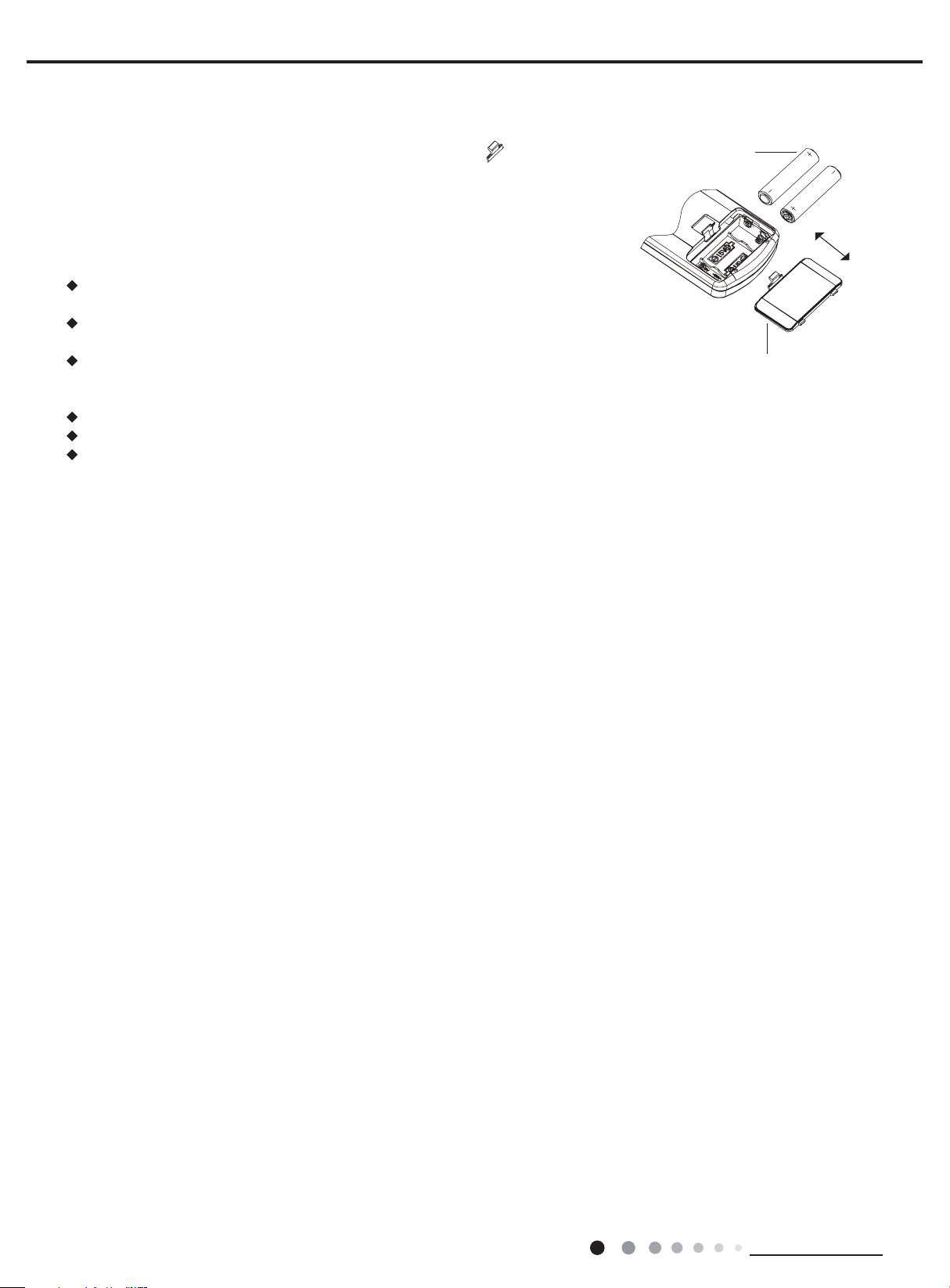
1. Press the back side of remote controller on the spot marked with
push out the cover of battery box along the arrow direction.
2. Replace two No.7 (AAA
polar are correct
3. Reinstall the cover of battery box.
Note:
window of the indoor unit;
There should be no obstacle between them.
or wireless telephone; Remote controller should be close to indoor unit during
operation.
batteries.
remove
Replacement of Batteries in Remote Controller
, and then
1.5V) dry batteries and make sure the positions of + and --
.
During operation, point the signal sender of the remote controller at the receiving
The distance between signal sender and receiving window should be within 8m.
Signal may be interfered easily in the room where there is fl uorescent lamp
Replace new batteries of the same model when replacement is required.
If you don't use remote controller for a long time, please take out the batteries.
If the display on remote controller is fuzzy or if there's no display, please replace
battery
reinstall
cover of battery box
16
Technical Information
Service Manual
HEALTH SAVE Button
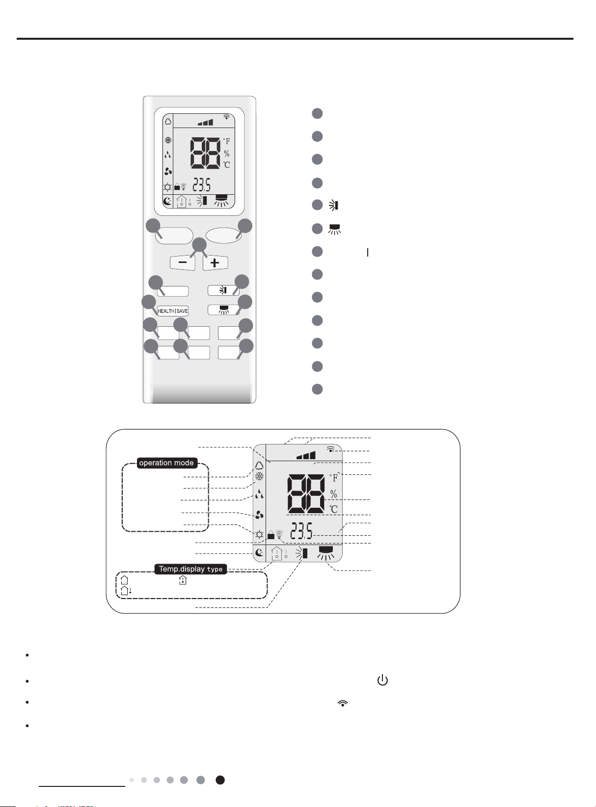
6.2 Remote Controller Introduction of YB1F2(XFAN)
Buttons on remote controller
1
FAN
AIR
HUMIDITY
FILTER
TURBO
AUTO
HEALTH
OPER
X-FAN
HOUR
ON/OFF
ON/OFF Button
2
MODE Button
3
+/- Button
4
FAN Button
5
Button
1
ON/OFF
3
4
FAN
7
8
11
Introduction for icons on display screen
Operation mode
Auto mode
Cool mode
Dry mode
Fan mode
Heat mode
:Outdoor ambient temp.
Up&down swing
9
X-FAN
TURBO
Child lock
Sleep mode
Temp. display type
12
Air mode
:Indoor ambient temp.:Set temp.
TEMP
SLEEP
MODE
TIMER
LIGHT
2
5
6
10
13
AUTO
FAN
HEALTH
AIR
HUMIDITY
FILTER
TURBO
6
Button
7
8
X-FAN Button
9
TEMP Button
10
TIMER Button
11
TURBO Button
12
SLEEP Button
13
LIGHT Button
OPER
X-FAN
HOUR
ON/OFF
(Note: X-FAN is same with BLOW)
Set fan speed
Send signal
Health mode
X-fan
Set temperature
Turbo mode
TIMER ON/TIMER OFF
Set time
Light
Left&right swing
Introduction for buttons on remote controller
Note:
This is a general use remote controller, it could be used for the air conditioners with multifunction; For some function, which the model
doesnt have, if press the corresponding button on the remote controller that the unit will keep the original running status.
After putting through power, air conditioner will give out a sound and operation indicator " " is ON (red indicator). You can operate the air
conditioner through the remote co ntroller.
At ON status, after each pressing button on remote controller, the signal icon " " on remode controller will ash once. Air conditioner will
give out a sound, which indicates the signal has been sent to air conditioner.
At OFF status, display screen on remote controller displays set temperature. At on status, display screen on remote controller displays
the corresponding start up functions icon.
Technical Information
17
Service Manual
1.ON/OFF button
Press this button can turn on or turn off the air conditioner. After turning on the unit,operation indicator " " on indoor unit is ON (green
indicator. Color may be differ-ent for different models)and indoor unit gives out a sound.
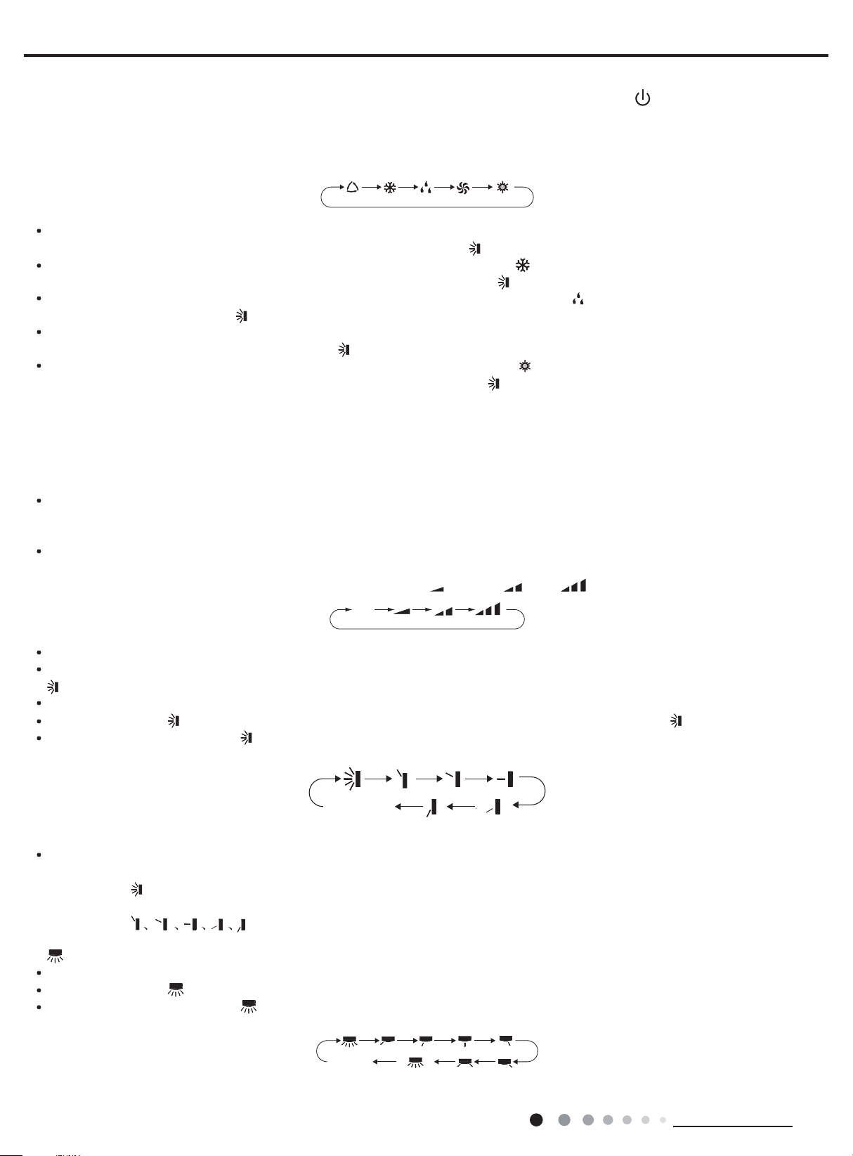
2.MODE button
Press this button can select your required operation mode.
AUTO COOL DRYF AN HEAT
After selecting auto mode, air conditioner will operate automatically according to ambient temperature. Set temperature cant be adjusted
and also cant be displayed. Press "FAN" button can adjust fan speed. Press " " button can adjust swing angle.
After selecting cool mode, air conditioner operates under cool mode. Cool indicator " " on indoor unit is ON. You can press "+" or "-"
button to adjust set temperature. Press "FAN" button can adjust fan speed. Press " " button can adjus t swing angle.
After selecting dry mode, air conditioner operates under dry mode at low speed. Dry indicator " " on indoor unit is ON. Under dry mode,
fan speed cant be adjusted. Press " " button to adjust swing angle.
After selecting fan mode, air conditioner operates only under fan mode, All mode indicators on indoor unit is OFF. Operation indicator is
ON. Press "FAN" button can adjust fan speed. Press " " button to adjust swing angle.
After selecting heat mode, air conditioner operates under heat mode. Heat indicator " " on indoor unit is ON. You can press "+" or "-"
button to adjust set temperature. Press "FAN" button to adjust fan speed. Press " " button to adjust swing angle. (Cooling only unit cant
receive the signal for heating mode.)
Note:
For preventing cold wind, after starting up heating mode, indoor fan will blow fan afterdelaying 1-5min. (Details time is decided by indoor
ambient temperature) Temperature setting range on remote controller: 16oC~30oC(61oF~86oF) . Fan speed setting range: auto, low speed,
medium speed and high speed.
3."+" or "-" button
After each pressing of "+" or "-" button, it can increase or decrease set temperature 1oC(1oF~2oF) . Hold "+" or "-" button, 2s later, set
temperature on remote controller will change quickly. After reaching to your required time, loosen the button. Temperature indicator on
indoor unit will also change accordingly. (Temperature cant be adjusted under auto mode)
Under TIMER ON, TIMER OFF or Clock setting, you can press "+"or "-" button to adjust time. (Refer to TIMER button for details)
4.FAN button
Pressing this button can set fan speed circularly as: auto (AUTO), low( ), medium( ), high( ).
AUTO
Note:
Under AUTO Speed,IDU fan motor will adjust the fan speed (high, medium or low speed) according to ambient temperature.
Fan speed under dry mode is low speed.
5. button
Press this button to start or stop up & down swing function.The remote controller defaults to simple swing condition.
Press "+" button and " " button at the same time at unit OFF to switch between simple swing and static swing; " " blinks for 2 seconds.
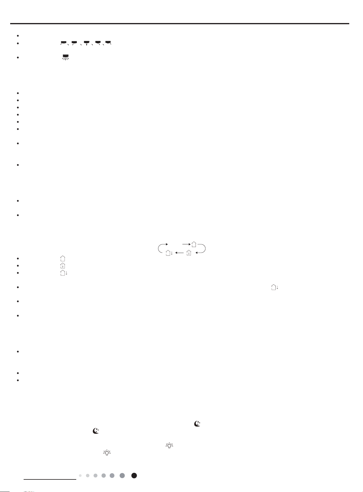
In static swing condition, pressing " " button, the swing angle of up & down louver changes as below:
no display
(horizontal louvers
stops at current
position)
If the unit is turned off during swing operation,the louver will stop at present position.
Note:
When selecting " " with remote controller, its auto swing. Horizontal louver of air conditioner will swing up&down automatically at the
maximum angle.
When selecting " " with remote controller, it is the xed position swing. Horizontal louver of air conditioner will stop at
that position as shown by the icon to swing.
6. button
Press this button to start or stop left & right swing function. The remote controller defaults to simple swing condition.
Press "+" button and " " button at the same time at unit OFF to switch between simple swing and static swing; blinks for 2 seconds.
In static swing condition, pressing " " button, the swing angle of left & right louver changes as below:
18
no display
(horizontal
louvers stops
at current
position)
(swing angle is
displayed
dynamically)
Technical Information
Service Manual
If the unit is turned off during swing operation,the louver will stop at present position.
When selecting " " with remote controller, it is the xed position swing. Horizontal louver of air conditioner will stop at
that position as shown by the icon to swing.
When selecting "(
swing angle is displayed dynamically
)" its the circulating swing. Horizontal louver of air conditioner will swing circularly according to
the angle as shown by the icon.
Note:
There is no this function for the units. If press this key, the main unit will click, but it also runs under original status.
7.HEALTH/SAVE button
After pressing HEALTH button, remote controller will switch circularly as below: "HEALTH"→"AIR"→"AIR HEALTH"→"no display"
When selecting "HEALTH" by remote controller, HEALTH function will be started up.
When selecting "AIR" by remote controller, AIR function will be started up.
When selecting "AIT HEALTH", AIR and HEALTH function will be started up.
When theres no display on remote controller, AIR and HEALTH function will be turned off.
AIR function is applicable for some models.
SAVE function:
Under cool mode, press SAVE button and the unit will operate under SAVE mode. Dual-8nixie tube on remote controller displays "SE".
Air conditioner will operate at auto speed. Set temperature cant be adjusted. Press SAVE button again to exit SAVE mode. Air conditioner
turn back to original set speed and set temperature.
This function is applicable to partial of models.
8.X-FAN button
After pressing this button under cooling or dry mode, remote controller displays the character of "X-FAN" and X-FAN function is started up.
Press this button again to cancel X-FAN function. The character of "X-FAN" will disappear.
Note:
After starting up X-FAN function, when turning off the unit, indoor fan will continue to operate for a while at low speed to dry the residual
water inside the indoor unit.
When the unit operates under X-FAN mode, press "X-FAN" button can turn off X-FAN function. Indoor fan stops operation immediately.
9.TEMP button
Press this button can see indoor set temperature, indoor ambient temperature or outdoor ambient temperature on indoor units display.
Temperature is set circularly by remote controller as below:
no display
When selecting " " by remote controller or no display, temperature indicator on indoor unit displays set temperature.
When selecting " " by remote controller, temperature indicator on indoor unit displays indoor ambient temperature.
When selecting " " by remote controller, temperature indicator on indoor unit displays outdoor ambient temperature.
Note:
Outdoor ambient temperature display may cant be selected for some models. When indoor unit receives " " signal, it displays indoor
set temperature.
Only for the model whose indoor unit has dual-8 display.
10.TIMER button
At ON status, press this button once can set TIMER OFF. The character of HOUR and OFF will ash.Press "+" or "-" button within 5s
can adjust the time of TEMER ON. After each pressing of "+" or "-" button, time will increase or decrease half an hour. When holding "+"
or "-" button, 2s later, the time will change quickly until to reach to your required time. After that, press "TIMER" button to conrm it. The
character of HOUR and OFF wont ash again.
Cancel TIMER OFF: Press "TIMER" button again under TIMER OFF status.
At OFF status, press this button once can set TIMER ON. Please refer to TIMER off for detailed operation.
Cancel TIMER ON: Press "TIMER" button again under TIMER ON status.
Note:
Time setting range: 0.5-24 hours.
Time interval between two operations cant exceed 5s. Otherwise, remote controller will exit the setting status automatically.
11.TURBO button
When pressing this button under cooling or heating mode, air conditioner will enter into quick cooling or quick heating mode. The
character of "TURBO" is displayed on remote controller. Press this button again to exit turbo function and the character of "TURBO" will be
disappeared on remote controller.
12.SLEEP button
Press this button under cooling, heating mode can start up sleep function." " icon will be displayed on remote controller. Press this button
again to cancel sleep function. " " icon on remote controller will be displayed.
13.LIGHT button
Press this button can turn off the light for indoor units display. " " icon on remote controller will disappear. Press this button again to turn
on the light for indoor units display. " " icon on remote controller will be displayed.
Technical Information
19

Service Manual
signal sender battery
Cover of battery box
remove
Function introduction for combination buttons
Child lock function
Press "+" and "-" buttons simultaneously can turn on or turn off child lock function. When child lock function is started up, " " icon will be
displayed on remote controller. If operate remote controller " " icon will ash three times, while remote controller wont send signal.
Switchover function for temperature display
After turning off the unit by remote controller, press "-" button and "MODE" button simultaneously to switch between oC and °F.
Operation guide
1. After putting through the power, press " " button on remote controller to turn on the air conditioner.
2. Press " " button to select your required mode: AUTO, COOL, DRY, FAN, HEAT.
MODE
ON/OFF
3. Press "+" or "-" button to set your required temperature. (Temperature cant be adjusted under auto mode).
4. Press " " button to set your required fan speed: auto, low, medium and high speed.
FAN
5. Press " " button to select fan blowing angle.
Replacement of batteries in remote controller
1. Press the back side of remote controller marked with " ", as shown in the g, and then push out the cover of battery box along the arrow
direction.
2. Replace two 7# (AAA 1.5V) dry batteries, and make sure the position of "+" polar and "-" polar are correct.
3. Reinstall the cover of battery box.
NOTICE
During operation, point the remote control signal sender at the receiving window on indoor unit.
The distance between signal sender and receiving window should be no more than 8m, and there should
reinstall
be no obstacles between them.
Signal may be interfered easily in the room where there is uorescent lamp or wireless telephone; remote
controller should be close to indoor unit during operation.
Replace new batteries of the same model when replacement is required.
When you dont use remote controller for a long time, please take out the batteries.
If the display on remote controller is fuzzy or theres no display, please replace batteries.
20
Technical Information
 Loading...