

Gree GPC12AL-K3NNA1A, GPH12AL-K3NNA1A, GPH12AL-K3NNA2A, GPH12AL-K3NNA3A Service Manual

Service Manual
GREE ELECTRIC APPLIANCES,INC.OF ZHUHAI
Change for Life
Service Manual
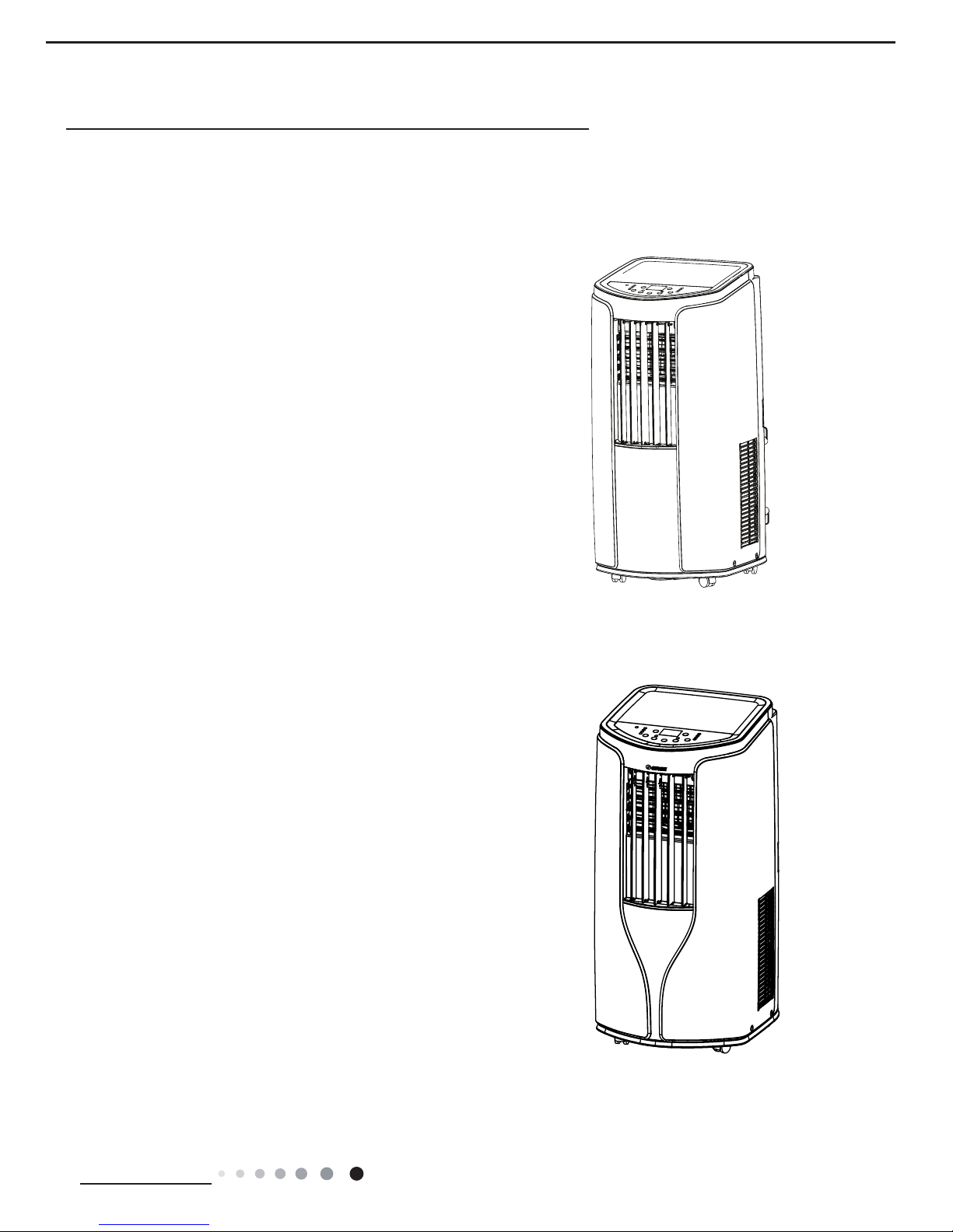
GPC12AL-K3NNA1A
GPH12AL-K3NNA1A
GPH12AL-K3NNA2A
GPH12AL-K3NNA3A
(Refrigerant R410A)
Models:

Service Manual
Table of Contents
Part
Ⅰ
: Technical Information
............................................................ 1
1. Summary
.................................................................................................... 1
2. Specications
.......................................................................................... 3
3. Outline Dimension Diagram
............................................................. 5
4. Refrigerant System Diagram
........................................................... 8
5. Electrical Part
........................................................................................... 9
5.1 Wiring Diagram ........................................................................................... 9
5.2 PCB Printed Diagram ................................................................................ 11
6. Function and Control
......................................................................... 13
6.1 Introduction of control panel ...................................................................... 13
6.2 Remote Controller Introduction ................................................................. 14
Part
Ⅱ
: Installation and Maintenance
......................................... 20
7. Notes for Installation and Maintenance
................................... 20
8. Install
.......................................................................................................... 23
8.1 Install Wire Hook ....................................................................................... 23
8.2 Removing Collected Water .......................................................................23
8.3 Installation and Disassembly of heat Discharge Pipe ............................... 25
8.4 Operation test ............................................................................................ 26
9. Maintenance
........................................................................................... 27
9.1 Error Code ................................................................................................. 27
9.2 Malfunction Detection Flowchart ............................................................... 29
9.3 Maintenance Method for Common Malfunction ........................................ 35
10. Exploded View and Parts List
.................................................... 37
11. Removal Procedure
.......................................................................... 49
Appendix:
...................................................................................................... 57
Appendix 1: Reference Sheet of Celsius and Fahrenheit ............................... 57
Appendix 2: List of Resistance for Temperature Sensor ................................. 58
Appendix 3: Resistance Value Table of Humidity Sensor ............................... 61
Table of Contents
1
Technical Information
Service Manual
GPC12AL-K3NNA1A
GPH12AL-K3NNA1A
GPH12AL-K3NNA2A
1. Summary
Part
Ⅰ
: Technical Information
Models:
Model:
2
Technical Information
Service Manual
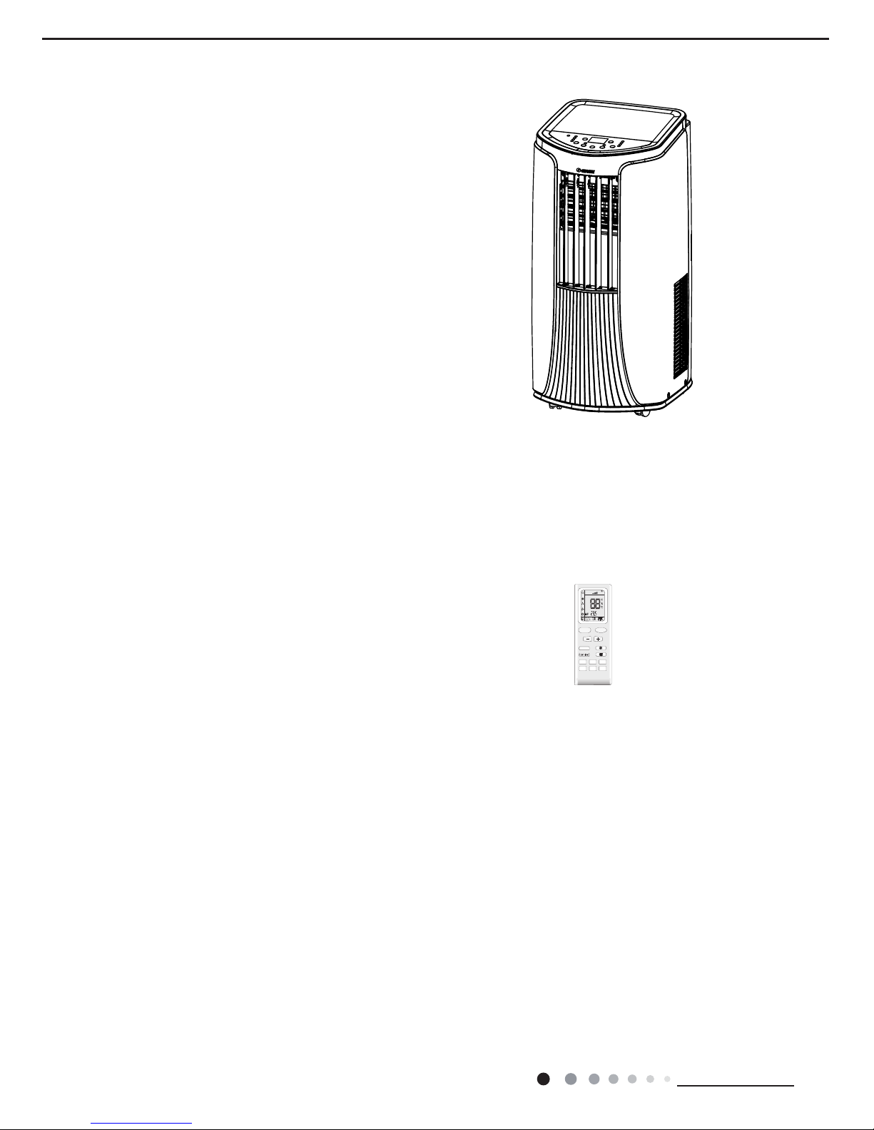
YB1F2(XFAN)
Remote Controller:
FAN
AUTO
OPER
HEALTH
AIR
FILTER
TURBO
ON/OFF
X-FAN
HOUR
HUMIDITY
ON/OFF
MODE
FAN
X-FAN
TURBO
TEMP
TIMER
SLEEP
LIGHT
GPH12AL-K3NNA3A
Model:
3
Technical Information
Service Manual
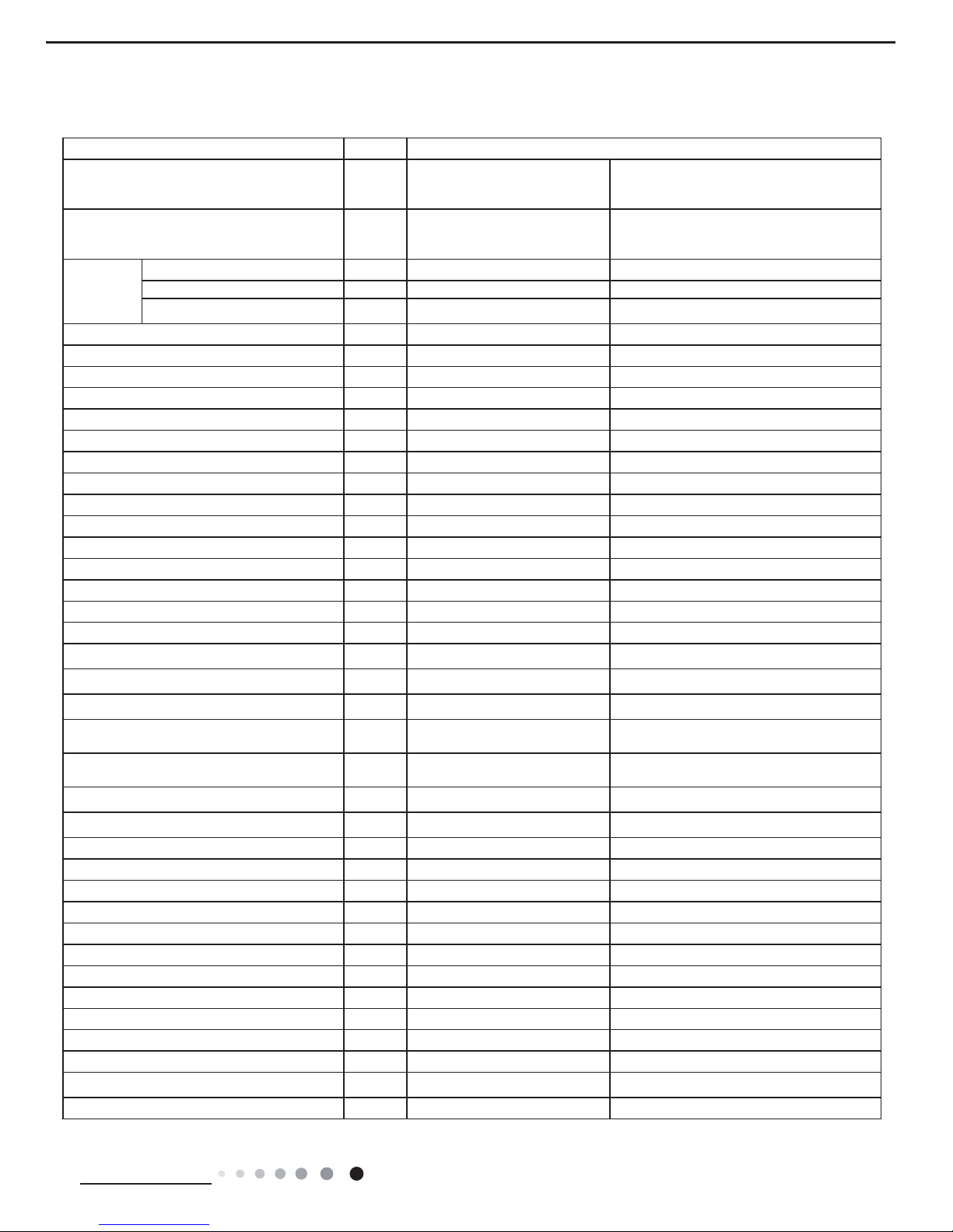
2. Specications
Parameter Unit Value
Model
GPC12AL-K3NNA1A
GPH12AL-K3NNA1A
GPH12AL-K3NNA2A
GPH12AL-K3NNA3A
Product Code
CK010025700
CK010025702
CK010024500
CK010025800
CK010025900
Power
Supply
Rated Voltage V
~
220-240 220-240
Rated Frequency Hz 50 50
Phases
1 1
Cooling Capacity W 3520 3520
Heating Capacity W / 3520
Cooling Power Input W 1345 1345
Heating Power Input W / 1235
Cooling Power Current A 6.0 6.0
Heating Power Current A / 5.5
Rated Input W 1550 1550
Rated Current
A
7.0 7.0
Air Flow Volume(H/M/L)
m3/h
360/330/300 360/330/300
Dehumidifying Volume L/h 1.6 1.6
EER W/W 2.61 2.61
COP W/W / 2.85
SEER / /
HSPF / /
Application Area m
2
15-22 15-22
Climate Type T1 T1
Isolation I I
Moisture Protection IPX0 IPX0
Permissible Excessive Operating Pressure for
the Discharge Side
MPa 4.3 4.3
Permissible Excessive Operating Pressure for
the Suction Side
MPa 2.5 2.5
Throttling Method Capillary Capillary
Defrosting Method / Automatic Defrosting
Fuse A 3.15 3.15
Operation Temp
o
C 16~30 16~30
Ambient Temp (Cooling)
o
C 16~35 16~35
Ambient Temp (Heating)
o
C / 10~27
Sound Pressure Level (H/M/L) dB (A) 53/51/49 53/51/49
Sound Power Level (H/M/L) dB (A) 65/64/63 65/64/63
Dimension (WXHXD) mm 390X820X405 390X820X405
Dimension of Carton Box (LXWXH) mm 578X452X847 578X452X847
Dimension of Package (LXWXH) mm 581X455X862 581X455X862
Net Weight kg 39 39
Gross Weight kg 44 44
Refrigerant R410A R410A
Refrigerant Charge kg 0.79 0.81
4
Technical Information
Service Manual
The above data is subject to change without notice. Please refer to the nameplate of the unit.
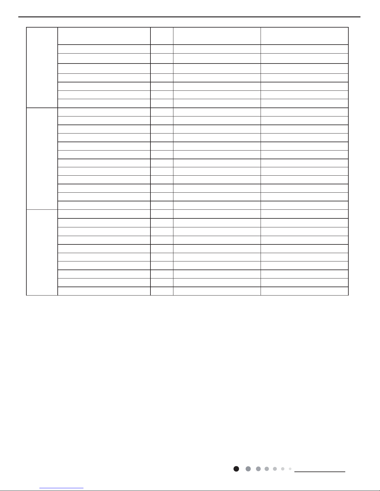
Compressor
Compressor Manufacturer/Trademark
ZHUHAI LANDA COMPRESSOR
CO., LTD
ZHUHAI LANDA COMPRESSOR
CO., LTD
Compressor Model QXA-C136B030B QXA-C136B030B
Compressor Oil POE(RB68EP) POE(RB68EP)
Compressor Type Rotary Rotary
L.R.A. A 27.00 27.00
Compressor RLA A 5.1 5.1
Compressor Power Input W 1115 1115
Overload Protector UP3-02 UP3-02
Evaporator
Fan Type Centrifugal Centrifugal
Diameter Length(DXL) mm Φ187.6X108.2 Φ187.6X108.2
Fan Motor Speed(H/M/L) r/min 1050/960/870 1050/960/870
Output of Fan Motor W 16 16
Fan Motor RLA A 0.3 0.3
Fan Motor Capacitor μF 3.5 3.5
Form Aluminum Fin-copper Tube Aluminum Fin-copper Tube
Pipe Diameter mm Φ7 Φ7
Row-n Gap mm 3-1.4 3-1.4
Coil Length (LXDXW) mm 442X38.1X228.6 442X38.1X228.6
Swing Motor Model / /
Output of Swing Motor W / /
Condenser
Fan Type Centrifugal Centrifugal
Fan Diameter mm Φ224.5X80 Φ224.5X80
Form Aluminum Fin-copper Tube Aluminum Fin-copper Tube
Pipe Diameter mm Φ7 Φ7
Rows-n Gap mm 3-1.4 3-1.4
Coil Length (LXDXW) mm 592X34.2X304.8/475X11.4X266.7 592X34.2X304.8/475X11.4X266.7
Fan Motor Speed rpm 1040/850 1040/850
Output of Fan Motor W 50 50
Fan Motor RLA A 0.53 0.53
Fan Motor Capacitor μF 3.5 3.5
5
Technical Information
Service Manual
Unit:mm
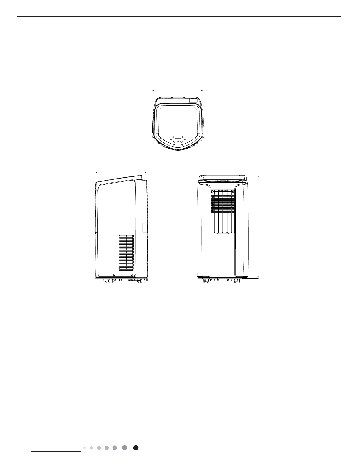
3. Outline Dimension Diagram
1:1
820
405
390
GPC12AL-K3NNA1A GPH12AL-K3NNA1A
6
Technical Information
Service Manual
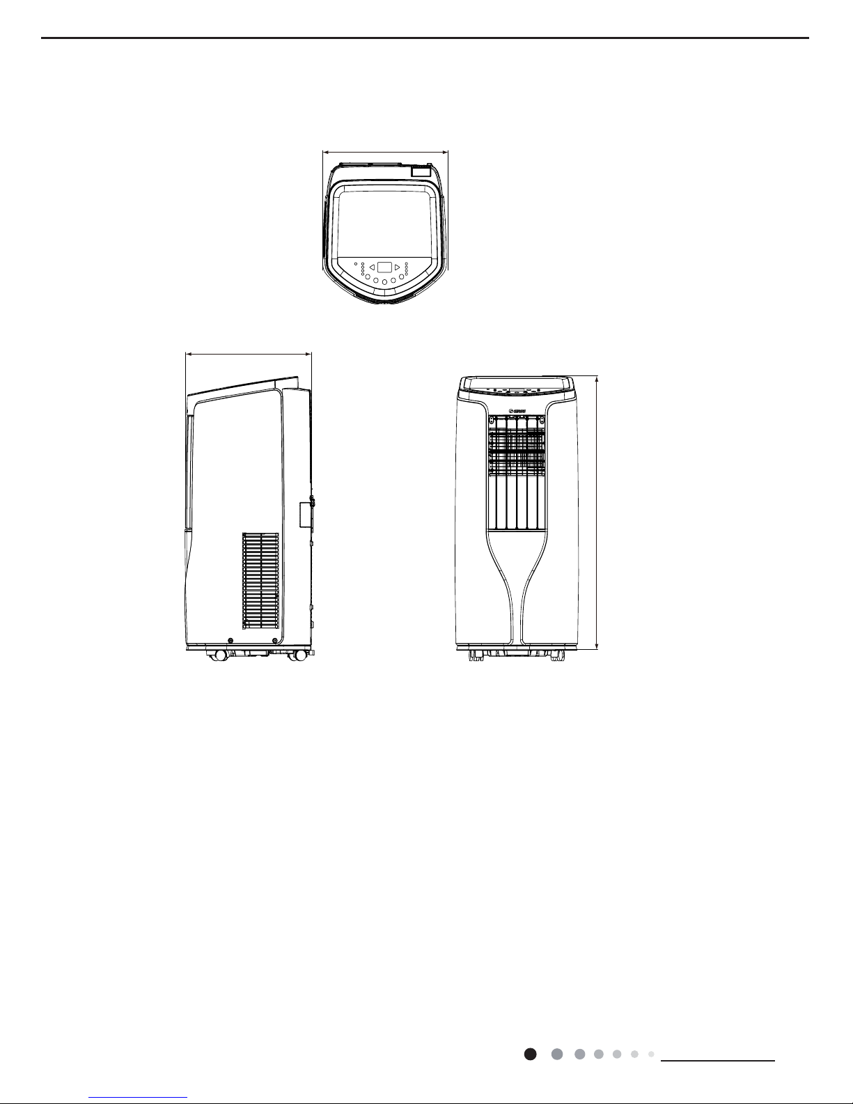
GPH12AL-K3NNA2A
390
820
405
Unit:mm
7
Technical Information
Service Manual
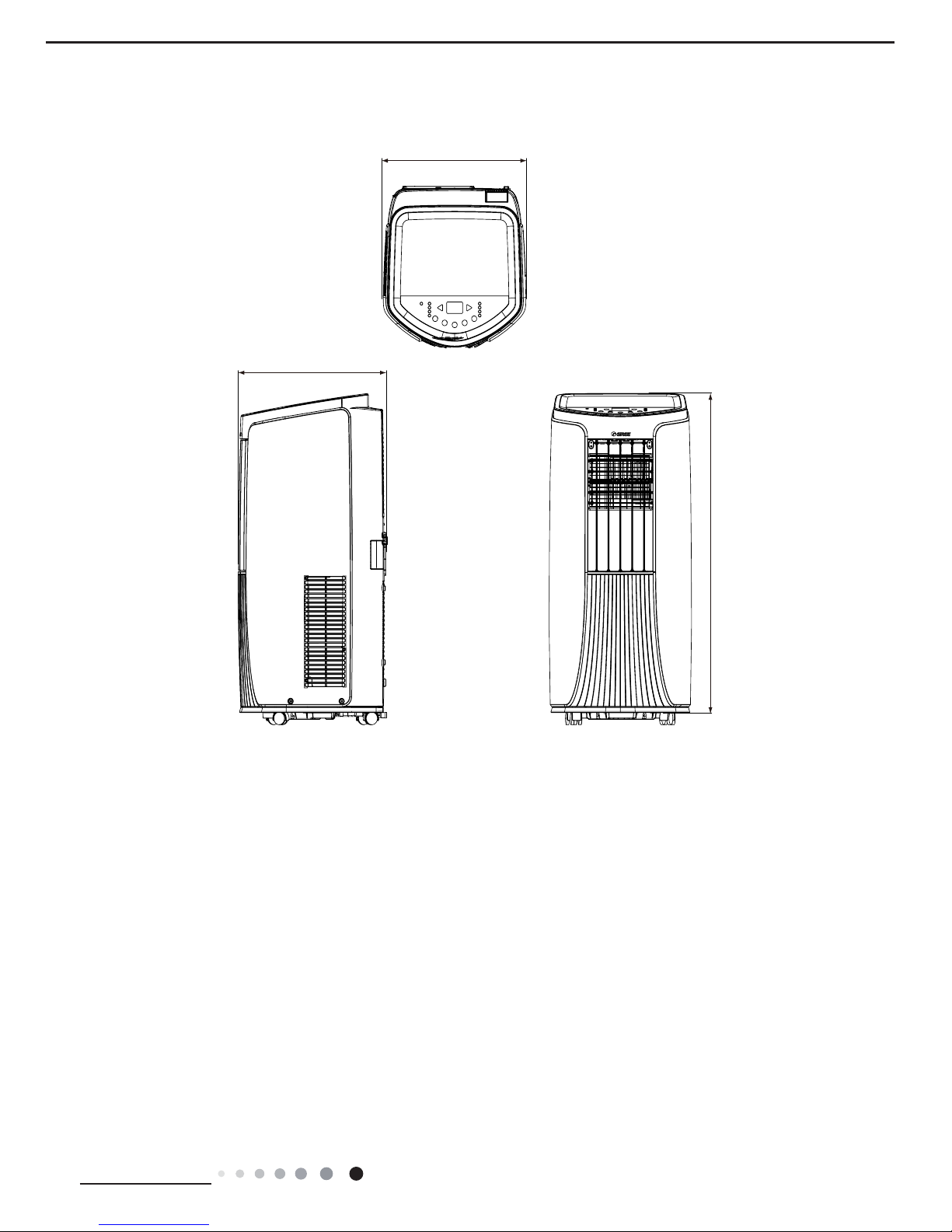
GPH12AL-K3NNA3A
Unit:mm
390
820
405
8
Technical Information
Service Manual
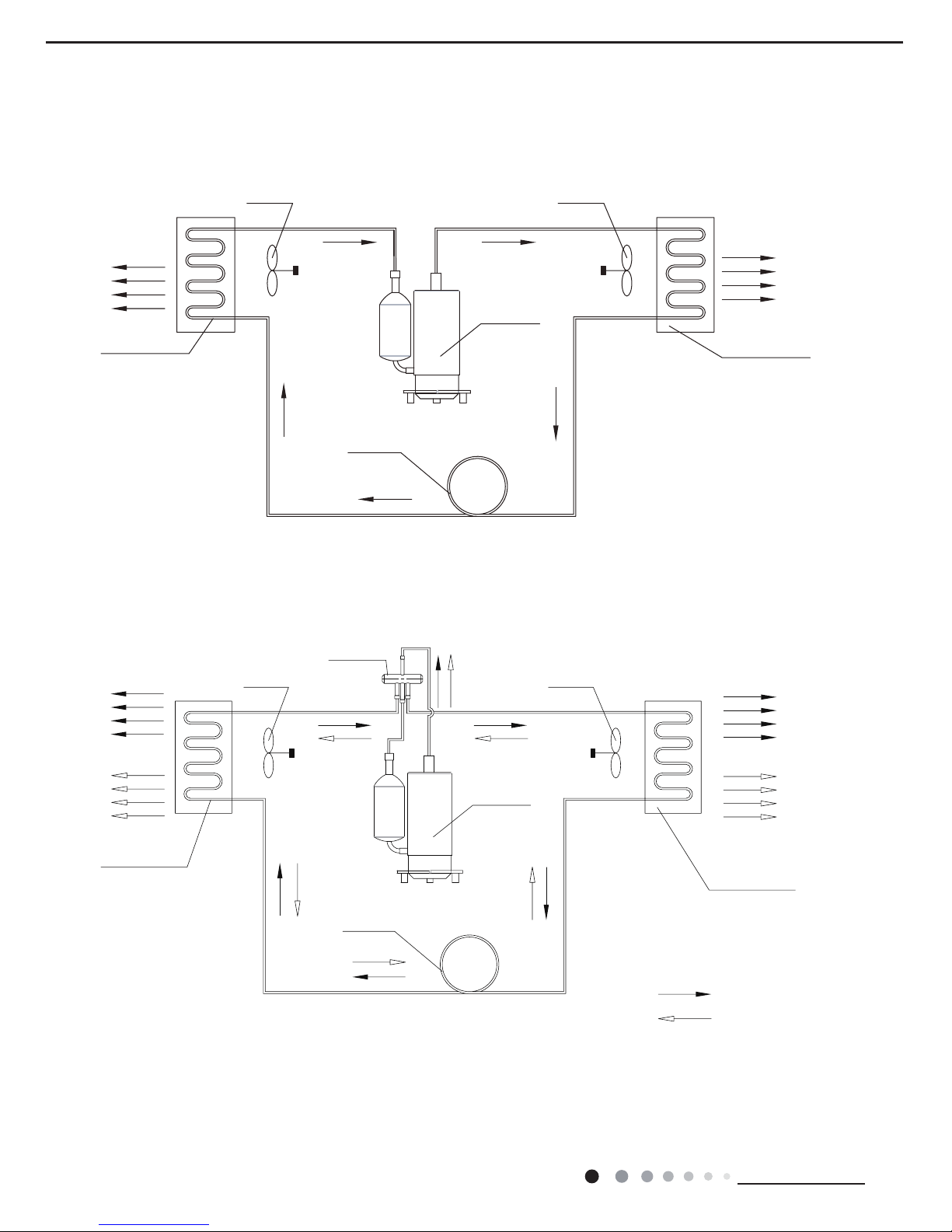
4. Refrigerant System Diagram
OUTDOOR COILS
HOT DISCHARGED AI
R
COMPRESSOR
CENTRIFUGAL FAN
CENTRIFUGAL FAN
CAPILLARY
REFRIGERANT FLOW DIRECTION
COOLED AIR
INDOOR COILS
OUTDOOR COILS
HOT DISCHARGED
AIR
COOLED AIR
COMPRESSOR
CENTRIFUGAL FAN
CENTRIFUGAL FAN
CAPILLARY
REFRIGERANT FLOW DIRECTION
NOTES:
COOLING MODE
HEATING MODE
HOT AIR
COOLED AIR
INDOOR COILS
4-Way valve
GPC12AL-K3NNA1A
GPH12AL-K3NNA1A GPH12AL-K3NNA2A GPH12AL-K3NNA3A
9
Technical Information
Service Manual
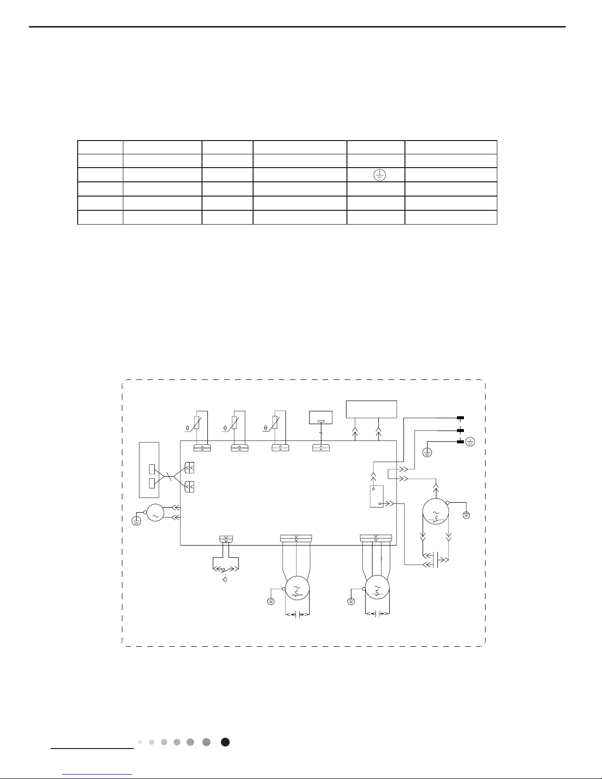
Symbol Symbol Color Symbol Symbol Color Symbol Name
WH White GN Green COMP Compressor
YE Yellow BN Brown Grounding wire
RD Red BU Blue / /
YEGN Yellow/Green BK Black / /
VT Violet OG Orange / /
5. Electrical Part
5.1 Wiring Diagram
●Instruction
●Electric Diagram
Model:GPC12AL-K3NNA1A
R(M)
OUTTUBE
OUTTUBE TEMP.
RT3
SENSOR
SWITCH
WATER LEVEL
SENSOR
TUBE TEMP.
TUBE
WATER
ROOM
POWER
L
BN(BK)
N
YEGN(GN)
BU(WH)
BU
N3
S
COMP
YEGN
C
YE
C1
K201
AC-L
COMP
N1
WATER1
DISP2
RD
RD
BU
SA
COM
WH
HIGH-WP
RD
DISP2
ROOM TEMP.
DISP1
AP2
M3
SENSOR
PE
PE
YEGN
RT2RT1
BK
NC
DISP1
M2
OFAN
YEGN
MOTOR
DOWN FAN
C3
C2
RD
UP FAN
MOTOR
BN
M1
FAN
BOARD
DISPLAY
REC
RECEIVER
AP3
BOARD
AP1
MAIN BOARD
BU
GENERATOR
COLD PLASMA
RD
HEALTH-N
HEALTH-L
COMP.
CAP.
CAP.
RD
BN
CAP.
YEGN
MOTOR
PE
PE
PE
60000700008501
10
Technical Information
Service Manual
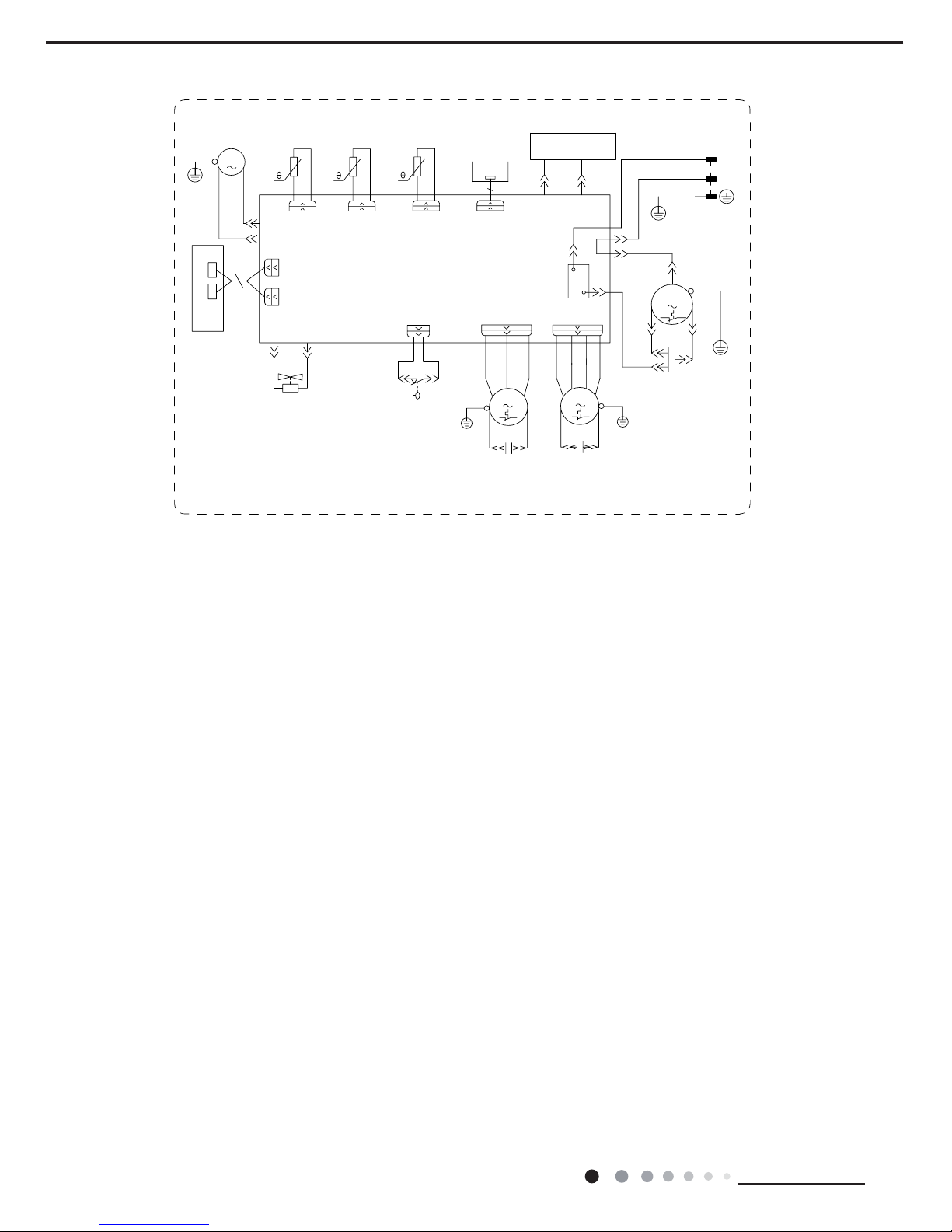
These wiring diagrams are subject to change without notice; please refer to the one supplied with the unit.
R(M)
OUTTUBE
OUTTUBE TEMP.
RT3
SENSOR
SWITCH
WATER LEVEL
SENSOR
TUBE TEMP.
TUBE
WATER MOTOR
ROOM
POWER
L
BN(BK)
N
YEGN(GN)
BU(WH)
BU
N3
S
COMP
YEGN
C
YE
C1
K201
AC-L
COMP
N1
WATER
DISP2
RD
RD
BU
SA
COM
WH
HIGH-WP
RD
DISP2
ROOM TEMP.
DISP1
AP2
M3
SENSOR
PE
PE
PE
YEGN
RT2RT1
BK
NC
DISP1
PE
PE
M2
OFAN
YEGN
MOTOR
DOWN FAN
C3
C2
UP FAN
MOTOR
M1
YEGN
FAN
BOARD
DISPLAY
REC
RECEIVER
AP3
BOARD
AP1
MAIN BOARD
BU
GENERATOR
COLD PLASMA
RD
HEALTH-N
HEALTH-L
N2
4YV
4WAY
4-WAY
VALVE
COMP.
RD
BN
CAP.
RD
BN
CAP.
CAP.
6361000045101
Models:GPH12AL-K3NNA1A GPH12AL-K3NNA2A GPH12AL-K3NNA3A
11
Technical Information
Service Manual
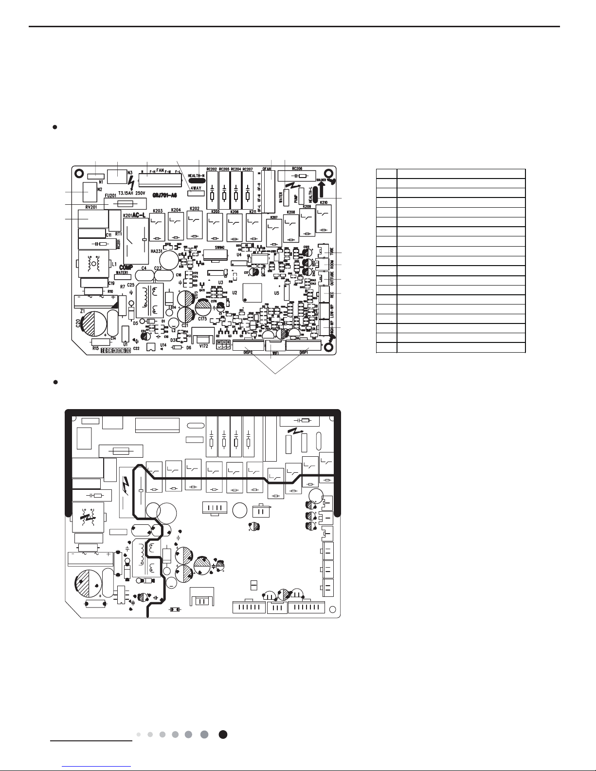
5.2 PCB Printed Diagram
TOP VIEW
BOTTOM VIEW
(1)Silk screen on main board
1
2
3
4
5
67
8
910
11
12
13
14
15
16
18
17
NO. NAME
1 Piezoresistor
2 Fuse
3 Copper fin N2 of neut ral wire
4 Copper fin N1 of neutral wire
5 Copper fin N3 of neutral wire
6 Indoor fan
7 4-way valve terminal
8 Neutral wire terminal
9 Outdoor fan
10 Copper fin water of
motor
11 Copper fin Health of live wire
12 Tube temperature sensor
13 Ambient temperature sensor
14 Outtube temperature sensor
15 Interface of remoter
16 High water level
17 Interface of display board
18 Interface of wifi board
12
Technical Information
Service Manual
TOP VIEW
BOTTOM VIEW
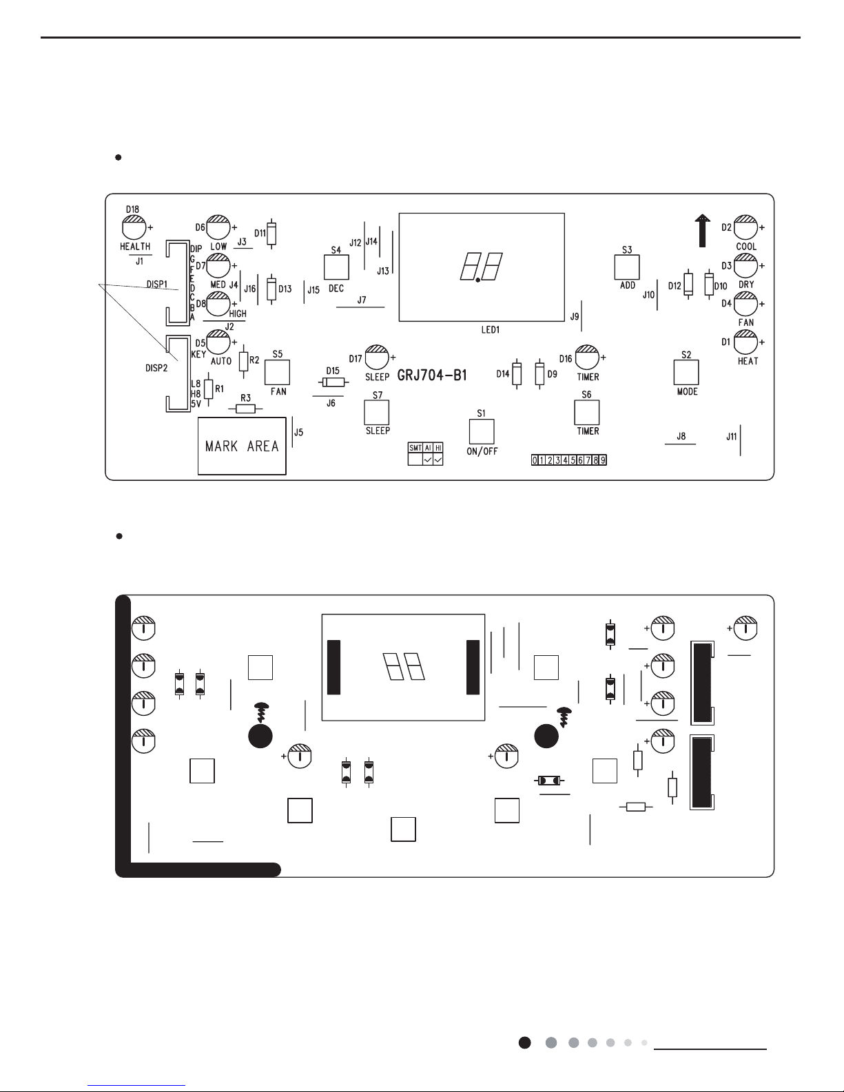
(2)Silk screen on display board
Interface of
main board
13
Technical Information
Service Manual
6. Function and Control
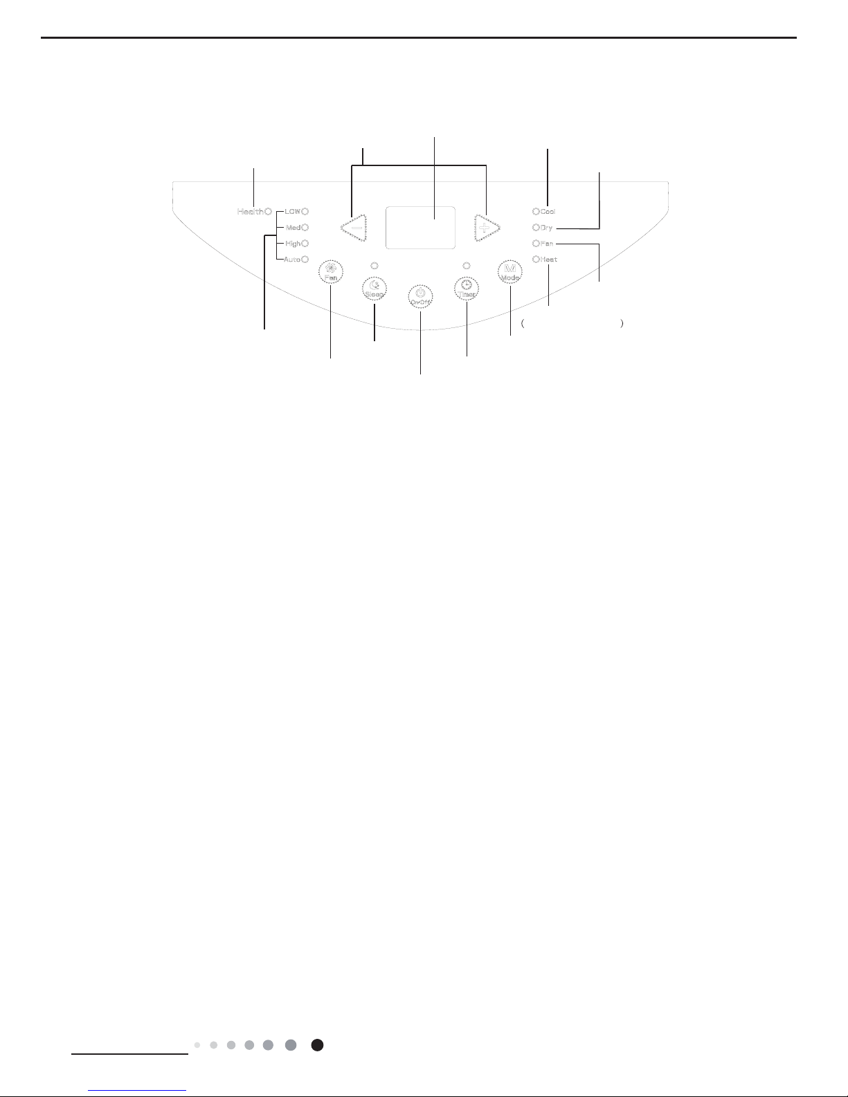
6.1 Introduction of control panel
Note:
●After putting through the power, the air conditioner will give out a sound. After that, you can operate the air conditioner by the control
panel.
● Under ON status, after each pressing of the button on control panel, the air conditioner will give out a sound. Meanwhile, corresponding
indicator on control panel will be bright.
● Under OFF status, dual-8 nixie tube on control panel wont display.
Under ON status, dual-8 nixie tube on control panel will display set temperature.
under cooling mode, while it wont display under other modes
1. ON/OFF button
Press this button to turn on or turn off air conditioner.
2. + / - button
Under cooling mode, press “+” or “-” button to increase or decrease set temperature by1°C(°F). Set temperature range is
16°C(61°F)~30°C(86°F). Under auto, drying or fan mode, this button is invalid.
3. Mode button
Press this button and the mode will circulate according to below sequence:
COOL→DRY→FAN
COOL: Under this mode, cooling mode indicator is bright. Dual-8 nixie tube displays set temperature. Temperature setting range
is16°C~30°C.
DRY: Under this mode, drying mode indicator is bright. Dual-8 nixie tube wont display.
FAN: Under this mode, air conditioner operates at set fan speed. Fan indicator and corresponding speed indicator is ON. Dual-8 nixie
tube wont display.(Note: You must connect the heat-discharge pipe before operating cooling or drying mode. No need for only fan mode.)
Heat Cool&Heat Unit only : Under this mode, heating mode indicator is bright.
Dual-8 nixie tube displays set temperature.
Temperature setting range is 16°C~30°C.
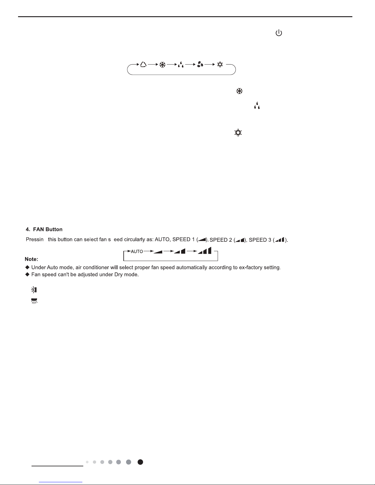
4. FAN button
Press this button and the fan speed will circulate as “low speed→medium speed →high speed→auto fan→low speed”.
5. Timer button
Press timer button to enter into timer setting mode. Under this mode, press " + " or " - " button to adjust the timer setting. Timer setting
will increase or decrease 0.5 hour by pressing " + " or " - " button within 10 hours, while timer setting will increase or decrease 1 hour by
pressing " + " or " - " button beyond 10 hours.After timer setting is nished, the unit will display temperature if theres no operation for
5s. If timer function is started up, the upper indicator will keep the display status. Others, it wont be displayed. Under timer mode, press
timer button again to cancel timer mode.
6. Sleep
● Press sleep button to enter into sleep mode. If the controller operates at cooling mode, after sleep mode is started up, preset
temperature will increase by 1°C within 1 hour ;preset temperature will increase by 2°C within 2 hours and then the unit will operate at
this temperature all the time;
● Press sleep button to enter into sleep mode. If the controller operates at heating mode, after sleep mode is started up, preset
temperature will decrease by 1°C within 1 hour ;preset temperature will decrease by 2°C within 2 hours and then the unit will operate at
this temperature all the time;
● Sleep function is not available for fan mode, drying mode. If sleep function is started up, the upper indicator will keep the display status.
Others, it wont be displayed.
Operation of control panel
ON/OFF button
Mode button
+ / - button
Dual-8 nixie tube
Fan mode indicator
Heat mode indicator
Cool&Heat Unit only
Cool mode indicator
Dry mode indicator
Sleep button
Fan button
Timer button
Fan speed indicator
Health indicator(Optional)
14
Technical Information
Service Manual
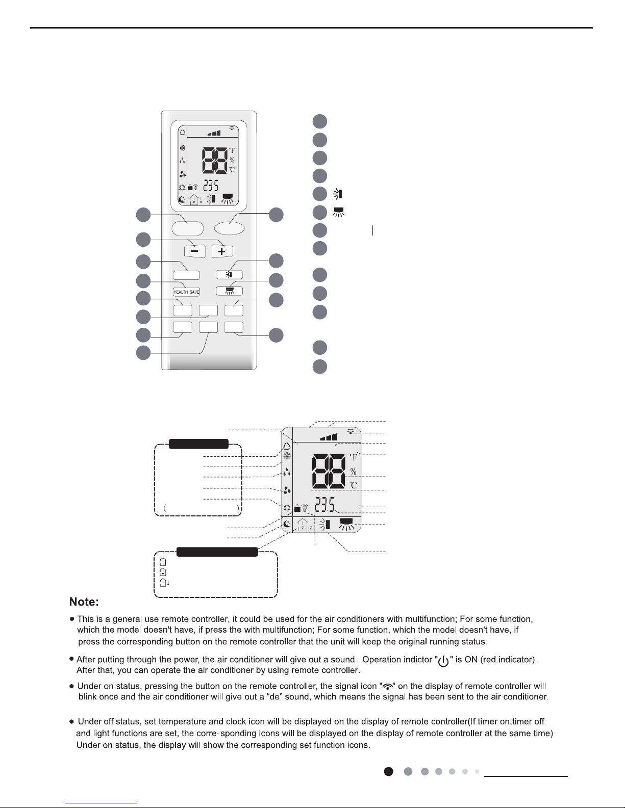
6.2 Remote Controller Introduction
Buttons on Remote Controller
Icon Display on Remote Controller
FAN
AUTO
OPER
HEALTH
AIR
FILTER
TURBO
ON/OFF
X-FAN
HOUR
HUMIDITY
ON/OFF
MODE
FAN
X-FAN
TURBO
TEMP
TIMER
SLEEP
LIGHT
2
5
6
10
13
12
11
9
8
3
4
7
1
1 ON/OFF button
2 MODE button
3 +/- button
4 FAN button
5 button(Not applicable for this unit)
8 X-FAN button
(Note: X-FAN is same with BLOW)
9 TEMP button
10 TIMER button
11 TURBO button
(Not applicable for this unit)
12 SLEEP button
13 LIGHT button
7 HEALTH SAVE button
6 button(Not applicable for this unit)
FAN
OPER
AUTO
HEALTH
AIR
FILTER
TURBO
ON/OFF
X-FAN
HOUR
HUMIDITY
Up & down swing
left & right swing
(Not applicable for this unit)
(Not applicable for this unit)
(Not applicable for this unit)
set time
TIMER ON/TIMER OFF
turbo mode
set temperature
X-fan
health mode
send signal
set fan speed
light
Temp. display type
:Set temp.
:Outdoor ambient temp.
(Not applicable for this unit)
:Indoor ambient temp.
Sleep mode
Child Lock
Hea
Cool&Heat Unit only
t mode
Fan mode
Dry mode
Cool mode
Auto mode
Operation mode
air mode
15
Technical Information
Service Manual
1.ON/DFF button
Press this button can turn on or turn off the air conditioner. After turning on the unit,operation indicator " " on the unit is ON (green
indicator. Color may be differ-ent for different models) and the unit gives out a sound.
2.MODE button
Press this button can select your required operation mode.
AUTO COOL FANDRYHEAT
● After selecting auto mode, air conditioner will operate automatically according to ambient temperature. Set temperature cant be
adjusted and also cant be displa- yed. Press "FAN" button can adjust fan speed.
● After selecting cool mode, air conditioner operates under cool mode. Cool indicator " " on the unit is ON. You can press "+" or "-"
button to adjust set temperature. Press "FAN" button can adjust fan speed.
● After selecting dry mode, air conditioner operates under dry mode at low speed. Dry indicator " " on the unit is ON. Under dry mode,
fan speed cant be ad- justed.
● After selecting fan mode, air conditioner operates only under fan mode, All mode indicators on the unit is OFF. Operation indicator is
ON. Press "FAN" button can adjust fan speed.
● After selecting heat mode, air conditioner operates under heat mode. Heat indicator " " on the unit is ON. You can press "+" or "-"
button to adjust set temperature.
Press "FAN" button to adjust fan speed.
(Cool&Heat Unit only)
Note:
For preventing cold wind, after starting up heating mode, indoor fan will blow fanafterdelaying 1-5min. (Details time is decided by indoor
ambient temperature)Temperature setting range on remote controller: 16℃-30℃. Fan speed setting range: auto, low speed, medium
speed and high speed.
3."+"or"-"button
● After each pressing of "+" or "-" button, it can increase or decrease set temperature 1℃. Hold "+" or "-" button, 2s later, set temperature
on remote controller will change quickly. After reaching to your required time, loosen the button. Temperature indicator on the unit will
also change accordingly. (Temperature cant be adjusted under auto mode)
5. button(Not applicable for this unit)
6. button(Not applicable for this unit)
7.HEALTH SAVE button
HEALTH FUNCTION:
After pressing HEALTH button, remote controller will switch circularly as below:"HEALTH"→"AIR"→"AIR HEALTH"→"no display"
● When selecting "HEALTH" by remote controller, HEALTH function will be started up.
● When selecting "AIR" by remote controller, AIR function will be started up. (Not applicable for this unit)
● When selecting "AIT HEALTH", AIR and HEALTH function will be started up.
● When theres no display on remote controller, AIR and HEALTH function will be turned off.
8.X-FAN button
After pressing this button under cooling or dry mode, remote controller displays the character of "X-FAN" and X-FAN function is started
up. Press this button again to cancel X-FAN function. The character of "X-FAN" will disappear.
Note:
● After starting up X-FAN function, when turning off the unit, indoor fan will continue to operate for a while at low speed to dry the
residual water inside the the unit.
● When the unit operates under X-FAN mode, press "X-FAN" button can turn off X-FAN function. Indoor fan stops operation immediately.
16
Technical Information
Service Manual
9.TEMP button
Press this button can see indoor set temperature, indoor ambient temperature or outdoor ambient temperature on the units display.
Temperature is set circularly by remote controller as below:
● When selecting " " by remote controller or no display, temperature indicator on the unit displays set temperature.
● When selecting " " by remote controller, temperature indicator on the unit displays indoor ambient temperature.
● When selecting " " by remote controller, temperature indicator on the unit displays outdoor ambient temperature.
Note:
● Outdoor ambient temperature display may cant be selected for some models.
When the unit receives " " signal, it displays indoor set temperature.
● Only for the model whose the unit has dual-8 display.
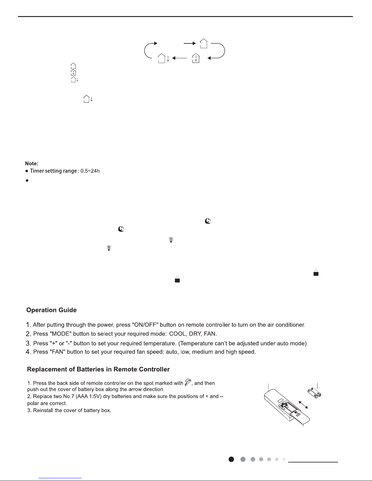
10.TIMER button
● At ON status, press this button once can set TIMER OFF. The character of HOUR and OFF will ash.Press"+"or"-"button within 5s
can adjust the time ofTIMER ON. After each pressing of "+" or "-" button, time will increase or decrease half an hour. When holding "+"
or "-" button, 2s later, the time will change quickly until to reach to your required time.After that,press"TIMER"button to conrm it.The
character of HOUR and OFF wont ash again.
Cancel TIMER OFF: Press "TIMER" button again under TIMER OFF status.● At OFF status, press this button once can set TIMER
ON. Please refer to TIMER off for detailed operation.
Cancel TIMER ON: Press "TIMER" button again under TIMER ON status.
no display
Time interval between two operations cant exceed 5s. Otherwise, remote controller will exit the setting status automatically.
11.TURBO button (Not applicable for this unit)
When pressing this button under cooling or heating mode, air conditioner will enter into quick cooling or quick heating mode. The
character of "TURBO" is displayed on remote controller. Press this button again to exit turbo function and the character of "TURBO"
will be disappeared on remote controller.
12.SLEEP button
Press this button under cooling, heating mode can start up sleep function." " icon will be displayed on remote controller. Press this
button again to cancel sleep function. " "icon on remote controller will be displayed.
13.LIGHT button
Press this button can turn off the light for the units display. " " icon on remotecontroller will disappear. Press this button again to turn
on the light for the units display. " " icon on remote controller will be displayed.
Function introduction for combination buttons
Child lock function
Press "+" and "-" buttons simultaneously can turn on or turn off child lock function. When child lock function is started up, " " icon will
be displayed on remote controller.If operate remote controller," "icon will ash three times,while remote controller wont send signal.
Switchover function for temperature display
After turning off the unit by remote controller, press "-" button and "MODE" buttonsimultaneously to switch between ℃and °F .
signal sender battery
Cover of battery box
remove
reinstall

17
Technical Information
Service Manual
NOTICE:
● During operation, point the remote control signal sender at the receiving window on the unit.
● The distance between signal sender and receiving window should be no more than 8m, and there should be no obstacles between
them.
● Signal may be interfered easily in the room where there is uorescent lamp or wireless telephone; remote controller should be close to
the unit during operation.
● Replace new batteries of the same model when replacement is required.
● When you dont use remote controller for a long time, please take out the batteries.
● If the display on remote controller is fuzzy or theres no display, please replace batteries.
18
Technical Information
Service Manual
6.3 Introduction of Basic Mode Function
1. Temperature Parameter
◆
Indo or setting temperature (Tpreset)
◆
Indoor ambient temperature (Tamb.)
2. Basic Functions of System
After the unit is energized, the interval of start-up time for compressor is no less than 3min under any conditions; when the compressor is
started, the unit is off without the temperature change in 6min.
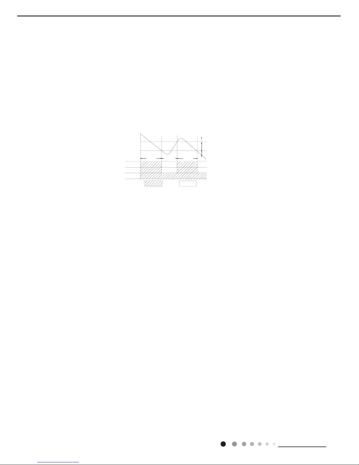
2.1 Cool Mode
2.1.1 Working conditions and process of cooling
a) When Tabm.≥Tpreset + 1oC (2oF), the unit will start to run in cooling mode, the compressor and kick motor start to run, and fan motor
runs under preset fan speed.
b) When Tabm.≤ Tpreset - 1oC (2oF), the compressor and kick motor stop to run, and fan motor runs under preset fan speed.
c) When Tpreset - 1oC (2oF)<Tamb.<Tpreset + 1oC (2oF), the unit will keep the current running status.Under this mode, the temperature
setting range is 61oF-86oF (16oC -30oC ).
a) Under cooling mode, after 1h of setting sleep process, Tpreset increases 2oF(1oC); 2h later, Tpreset increases 4oF(2oC). After 2h, the
setting temperature never increases, but the upper limit of increased setting temperature is 86oF(30oC)
b) Under heating mode, after 1h of setting sleep process, Tpreset decreases 2oF(1oC); 2h later, Tpreset decreases 4oF(2oC). After 2h, the
setting temperature never decreases, but the upper limit of decreased setting temperature is 61oF(16oC)
c) There is no sleep function under fan and dry mode.
d) When set sleep function, shift mode will cancel sleep function.
e) The setting temperature display is the same with remote controller; it is not inuenced by the setting temperature increases/ decreases.
2.2 Heating mode
When Tamb. ≤Tpreset+3°C(6°F), the unit operates in heating mode. Meanwhile, 4-way valve, compressor operates, and indoor fan
operates at cold air prevention condition;
When Tpreset+3°C(6°F)<Tamb.<Tpreset+5°C(10°F), the unit keeps original operation status,
When Tamb.≥Tpreset+5°C(10°F), compressor stop operation simultaneously. 4-way valve stop operation after the compressor has
stopped for 2 minutes. Indoor fan operates at blowing residual heat conditioner.
Under this mode, the temperature setting range is 16-30°C(61-86°F).
3.3 Auto Fan
a) Auto fan speed under Cooling mode;
Tamb≥Tpreset+4oF(2oC) High fan;
Tpreset<Tamb.< Tpreset+4oF(2oC) Med fan;
Tamb≤Tpreset Low fan;
b) There is 3.5min delay for auto fan shift.
3.4 TIMER Function
● General timer
a) TIMER ON: It can set timer on when the system is off, the setting time range is 0.5h-24h, when the time of setting timer on reaches, and
the system runs with the previous setting mode.
b) TIMER OFF: It can set timer on when the system is on, the setting time range is 0.5h-24h, when the time of setting timer off reaches,
the system stop to work.
● Clock timer
a) TIMER ON: If set timer on when the system is running, it continues to run; if set timer on when the system is off, when the time of setting
timer on reaches, and the system runs with the previous setting mode.
b) TIMER OFF: If set timer off when the system is off, the system keeps the stand-by status when setting timer off; if set timer off when the
system is on, when the time of timer off reaches, the system stops to run.
3.5 Memory Function
The system memories the setting running status of previous power-off, and runs automatically with the setting running status before it
power-off when it is energized again. If the unit is on before power-off, the compressor will 3min delay protection when it is energized
again.
3.6 Indicator Lamp, dual-8 digital pipe
a) When the unit runs, under cooling mode, cooling indicator lamp lights, dual-8 displays preset temperature.
b) When the unit runs, under fan mode, fan indicator lamp lights, dual-8 does not display.
c) When the unit runs, under dry mode, dry indicator lamp lights, dual-8 does not display.
d) When the unit runs, under heating mode, heating indicator lamp lights, dual-8 displays preset temperature.
Tpreset +1 ˚C
Tpreset –1 ˚C
Compressor
Outdoor fan
Indoor fan
Run
Tamb.
Stop
Stop cooling
Start cooling
Original operating status
≥ 6 min. ≥ 3 min. ≥ 6 min.
Setting fan speed

19
Technical Information
Service Manual
3.7 Setting button function
a) ON/OFF button: It controls systems switch.
b) Mode button: Mode setting cycle with below sequence: Cooling only unit: cooling-> dry-> fan.
c) Temp. ▼ button: Set temperature when the unit is on, the setting temperature decreases 1oC or oF per press
Temp. ▼ button; it will never setting when the setting reaches to 16oC or 61oF. The button is not valid under auto, dry and fan mode.
d) Temp. ▲ button: Set temperature when the unit is on, the setting temperature increases 1oC or oF per press
Temp. ▲ button; it will never setting when the setting reaches to 30oC or 86oF. The button is not valid under auto, dry and fan mode.
3.8 Light Control
If set the light is on with remote control, the indicator lamp and dual-8 display the current setting status; if set the
light is off with remote control, turn off the lamp immediately. If there is front panel button or remote control button
operation when setting light off with remote control, the indicator lamp and dual-8 display current setting status,
and turn off the light 5S later. Remote control light button does not controlled by failure display.
3.9 Protection Function
● Anti-freeze Protection
When the anti-freeze protection is inspected, the compressor stops, fan motor runs with setting fan speed.
When the anti-freeze protection is canceled and reaches to the 3min time-delay, it runs with the original status.
Temperature sensor failure inspection
a) Environment temperature sensor is open, short circuit: dual-8 displays F1, the cooling indicator lamp goes out 3S and blinks 1
time, and it will light up 0.5S and go out 0.5S when it is blinking.
b) Indoor pipe temperature sensor is open, short circuit: dual-8 displays F2, the cooling indicator lamp goes out 3S and blinks 2
times, and it will light up 0.5S and go out 0.5S when it is blinking.
c) Outdoor pipe temperature sensor is open, short circuit: dual-8 displays F4, the cooling indicator lamp goes out 3S and blinks 4
times, and it will light up 0.5S and go out 0.5S when it is blinking.
d) The compressor or electric heating pipe stops when the temperature sensor failure and the unit is on, The fan motor will be deal
regarding compressor or electric pipe reach to the temperature point and stops.
● Over current Protection
If the system current is inspected too large for 3min continuously, the fan motor runs with setting conditions, other load stops; 3min
later, the unit runs with the previously status; if over current protection occurs for 6 times continuously, display error code “E5”, the
load stops this time; if block the button except ON/OFF button, it will remote control the unit to off then on, or turn off with button, or
re-energized; the time of over current protection will zero clearing with remote control, press to turn on or re-energized.
● Over-ow Protection
If the over-ow is detected for 3S, it will enter into over-ow protection. Display error code H8, heating indicator lamp or over-ow
indicator lamp goes out 3S and blinks 8 times.
 Loading...