

Gree GPE12AF-K3NNA7A, GPE12AF-K3NNA7D, GPC12AF-K3NNA7D, GPC12AF-K3NNA7A, GPH12AF-K3NNA7E Service Manual
...
Service Manual
GREE ELECTRIC APPLIANCES,INC.OF ZHUHAI
Change for Life
Service Manual
Models: GPC12AF-K3NNA7A
GPC12AF-K3NNA7D
GPE12AF-K3NNA7A
GPE12AF-K3NNA7D
GPH12AF-K3NNA7A
GPH12AF-K3NNA7D
GPH12AF-K3NNA7E
(Refrigerant R410A)

Service Manual
Table of Contents
Table of Contents
Part
Ⅰ
: Technical Information
.......................................................................1
1. Summary
......................................................................................................................1
2. Specications
..........................................................................................................2
3. Outline Dimension Diagram
........................................................................8
4. Refrigerant System Diagram
......................................................................9
5. Electrical Part
.........................................................................................................10
5.1 Wiring Diagram ...............................................................................................................10
5.2 PCB Printed Diagram .....................................................................................................12
6. Function and Control
......................................................................................14
6.1 Remote Controller Introduction ......................................................................................14
6.2 Introduction of Basic Mode Function ..............................................................................18
Part
Ⅱ
: Maintenance
..........................................................................................20
7. Notes Maintenance
...........................................................................................20
8. Installation
................................................................................................................23
9. Maintenance
............................................................................................................32
9.1 Error Code ......................................................................................................................32
9.2 Malfunction Detection Flowchart ....................................................................................34
9.3 Maintenance Method for Common Malfunction ..............................................................39
10. Exploded View and Parts List
..............................................................41
11. Removal Procedure
.......................................................................................52
Appendix:
........................................................................................................................58
Appendix 1: Reference Sheet of Celsius and Fahrenheit ....................................................58
Appendix 2: Resistance Table of Ambient Temperature Sensor...........................................59
Appendix 3: Resistance Value Table of Humidity Sensor ..................................................... 62
1
Technical Information
Service Manual
GPC12AF-K3NNA7A
GPC12AF-K3NNA7D
GPE12AF-K3NNA7A
GPE12AF-K3NNA7D
GPH12AF-K3NNA7A
GPH12AF-K3NNA7D
GPH12AF-K3NNA7E
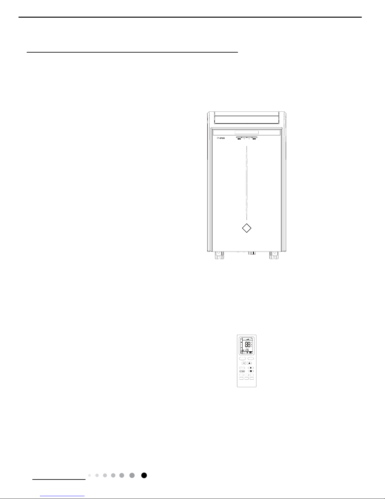
YB1F2(X-FAN)
1. Summary
Part
Ⅰ
: Technical Information
FAN
AUTO
OPER
HEALTH
AIR
FILTER
TURBO
ON/OFF
X-FAN
HOUR
HUMIDITY
ON/OFF
MODE
FAN
X-FAN
TURBO
TEMP
TIMER
SLEEP
LIGHT
Remote Controller
Models:
2
Technical Information
Service Manual
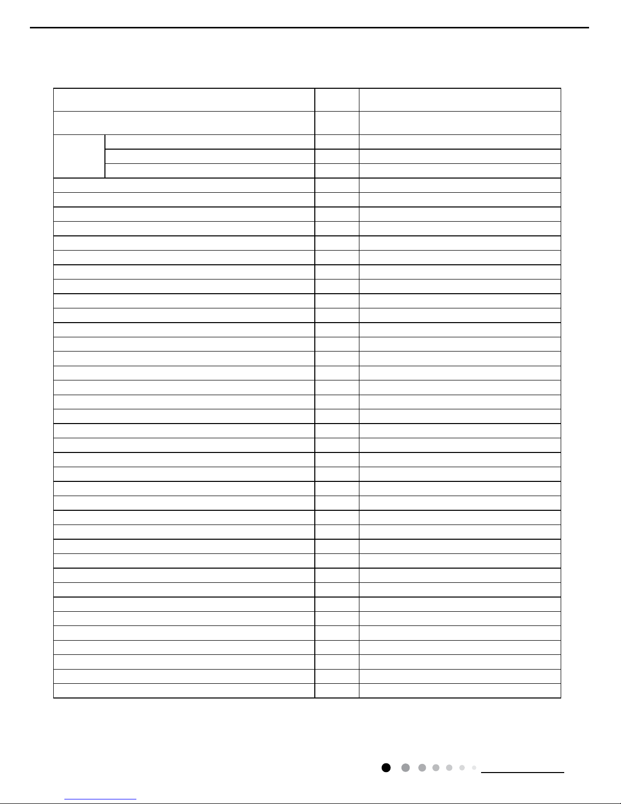
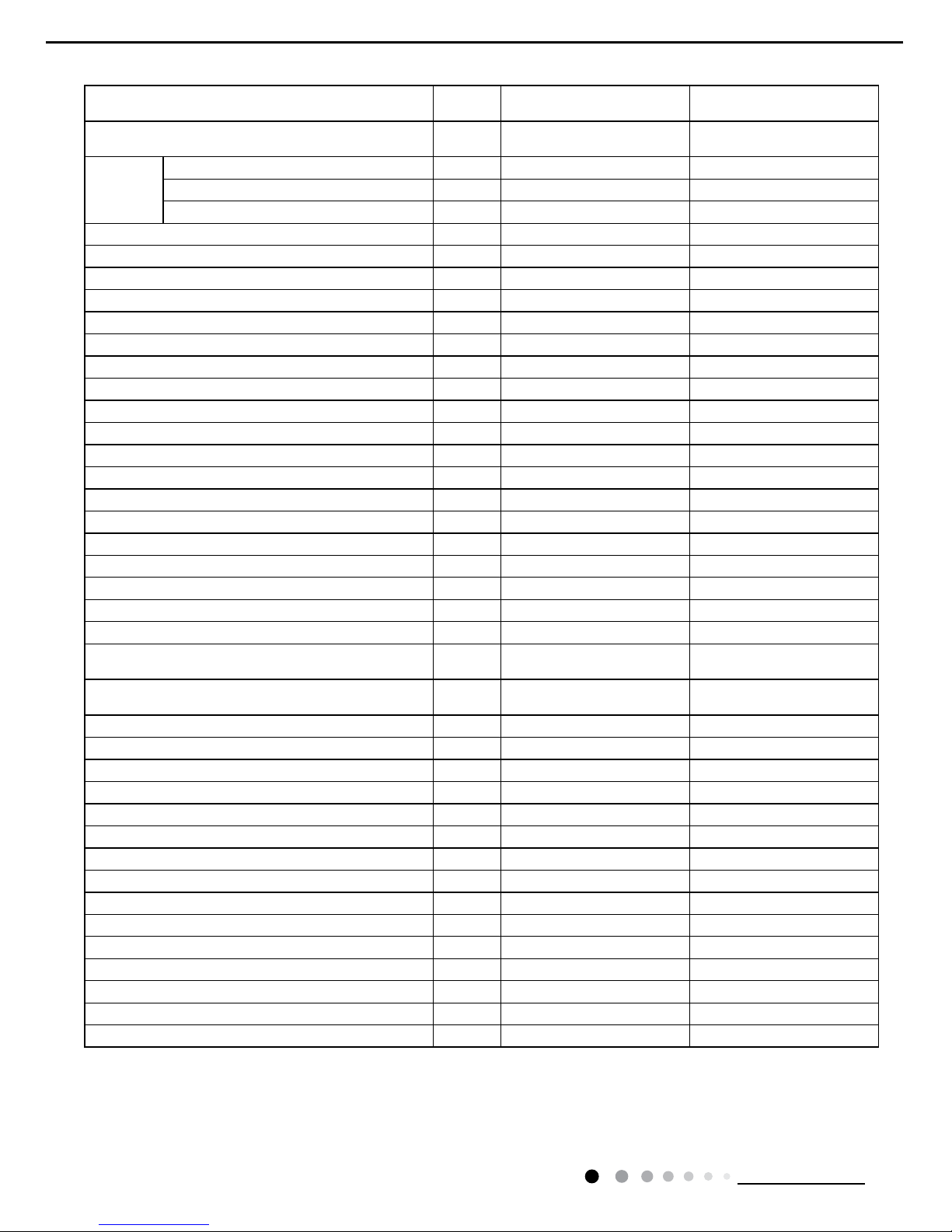
2. Specications
Model
1.GPC12AF-K3NNA7A
2.GPC12AF-K3NNA7D
Product Code
1.CK01001212
2.CK010021500 CK010021501
Power
Supply
Rated Voltage V~ 220-240
Rated Frequency Hz 50
Phases 1
Cooling Capacity W 3500
Heating Capacity W /
Cooling Power Input W 1340
Heating Power Input W /
Cooling Power Current A 7.50
Heating Power Current A /
Rated Input W 1550
Rated Current A 6.7
Input of Heater W /
Air Flow Volume(H/M/L) m
3
/h 450/420/390
Dehumidifying Volume L/h 1.5
EER W/W 2.61
COP W/W /
SEER W/W /
HSPF W/W /
Application Area m
2
15-22
Climate Type T1
Isolation I
Moisture Protection IPX0
Permissible Excessive Operating Pressure for the Discharge Side MPa 3.8
Permissible Excessive Operating Pressure for the Suction Side MPa 1.2
Throttling Method Capillary
Defrosting Method /
Fuse A 3.15
Operation Temp
℃
16~30
Ambient Temp (Cooling)
℃
10~35
Ambient Temp (Heating)
℃
/
Sound Pressure Level (H/M/L) dB (A) 58/56/52
Sound Power Level (H/M/L) dB (A) 68/66/62
Dimension (WXHXD) mm 500X840X460
Dimension of Carton Box (LXWXH) mm 581X536X862
Dimension of Package (LXWXH) mm 584X539X877
Net Weight kg 45
Gross Weight kg 52.5
Refrigerant R410A
Refrigerant Charge kg 0.8
3
Technical Information
Service Manual
The above data is subject to change without notice. Please refer to the nameplate of the unit.
Compressor
Compressor Manufacturer/Trademark Zhuhai Landa Compressor Co., Ltd/GREE
Compressor Model QXA-C133B030gA
Compressor Oil RB68EP/FVC68D
Compressor Type Rotary
L.R.A. A 32
Compressor RLA A 5.05
Compressor Power Input W 1130
Overload Protector build in
Evaporator
Fan Type Centrifugal
Diameter Length(DXL) mm Φ218X109
Fan Motor Speed(H/ML) r/min 800/700/600
Output of Fan Motor W 23
Fan Motor RLA A 0.1
Fan Motor Capacitor μF 2
Form Aluminum Fin-copper Tube
Pipe Diameter mm Φ7
Row-n Gap mm 3-1.6
Coil Length (LXDXW) mm 363X38.1X285
Swing Motor Model MP28GA
Output of Swing Motor W 2
Condenser
Fan Type Centrifugal
Fan Diameter mm 218X109
Form Aluminum Fin-copper Tube
Pipe Diameter mm Φ7
Rows-n Gap mm 4-1.6
Coil Length (LXDXW) mm 350X50.8X350
Fan Motor Speed rpm 1160
Output of Fan Motor W 65
Fan Motor RLA A 0.28
Fan Motor Capacitor μF 3
4
Technical Information
Service Manual
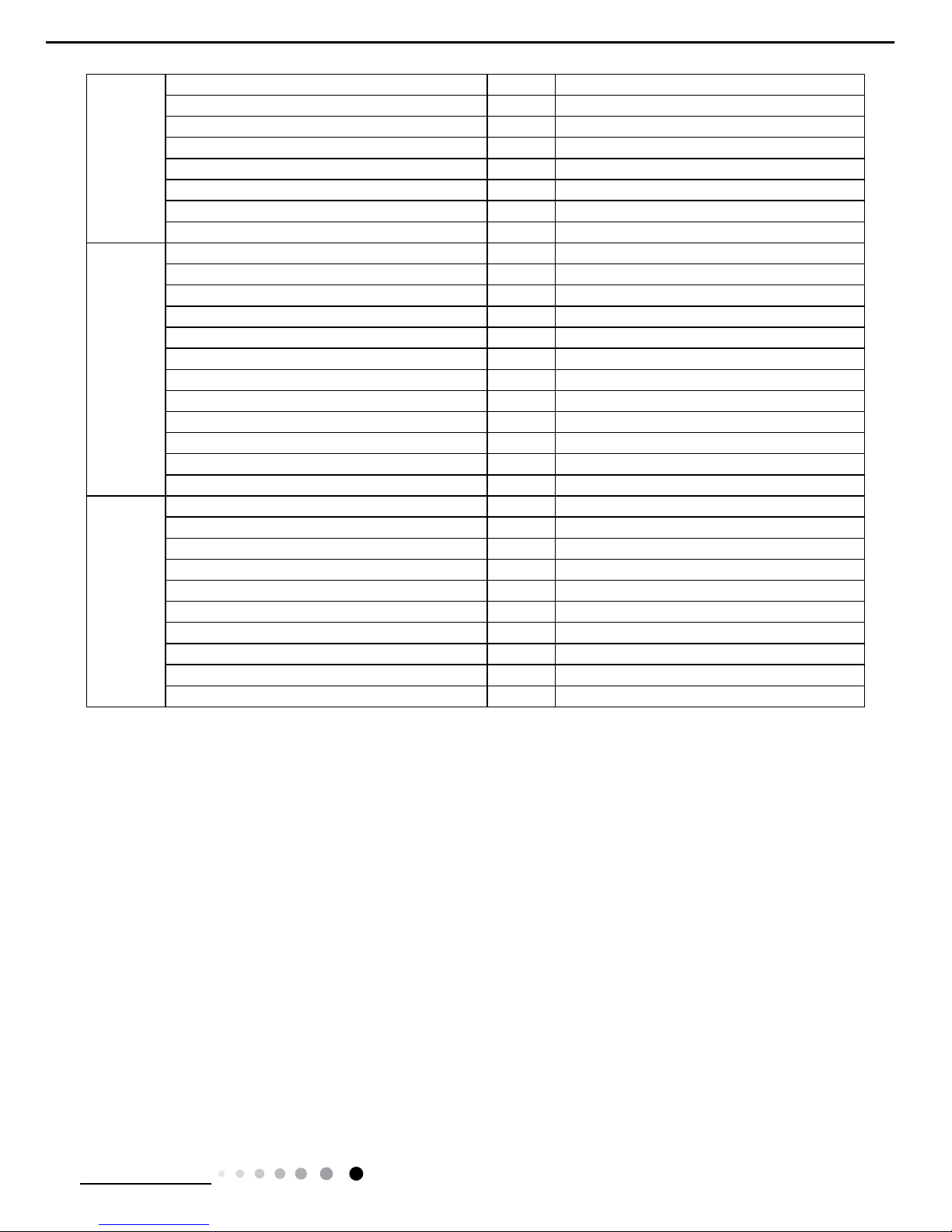
Model
1.GPE12AF-K3NNA7A
2.GPE12AF-K3NNA7D
GPE12AF-K3NNA7D
Product Code
1.CK01001452
2.CK010021600
CK010021601
Power
Supply
Rated Voltage V~ 220-240 220-240
Rated Frequency Hz 50 50
Phases 1 1
Cooling Capacity W 3500 3500
Heating Capacity W 2000 2000
Cooling Power Input W 1340 1340
Heating Power Input W 2100 2100
Cooling Power Current A 7.50 5.82
Heating Power Current A 9.00 9.13
Rated Input W 2200 2200
Rated Current A 11.00 9.57
Input of Heater W 1200 1200X2
Air Flow Volume(H/M/L) m
3
/h 450/420/390 450/420/390
Dehumidifying Volume L/h 1.5 1.5
EER W/W 2.61 2.61
COP W/W 0.95 0.95
SEER W/W / /
HSPF W/W / /
Application Area m
2
15-22 15-22
Climate Type T1 T1
Isolation I I
Moisture Protection IPX0 IPX0
Permissible Excessive Operating
Pressure for the Discharge Side
MPa 3.8 3.8
Permissible Excessive Operating
Pressure for the Suction Side
MPa 1.2 1.2
Throttling Method Capillary Capillary
Defrosting Method / /
Fuse A 3.15 3.15
Operation Temp
℃
16~30 16~30
Ambient Temp (Cooling)
℃
10~35 10~35
Ambient Temp (Heating)
℃
/ /
Sound Pressure Level (H/M/L) dB (A) 58/56/52 58/56/54
Sound Power Level (H/M/L) dB (A) 68/66/62 65/63/61
Dimension (WXHXD) mm 500/840/460 500X840X460
Dimension of Carton Box (LXWXH) mm 581X536X862 581X536X862
Dimension of Package (LXWXH) mm 584X539X877 584X539X877
Net Weight kg 45 45
Gross Weight kg 52.5 52.5
Refrigerant R410A R410A
Refrigerant Charge kg 0.8 0.8

5
Technical Information
Service Manual
The above data is subject to change without notice. Please refer to the nameplate of the unit.
Compressor
Compressor Manufacturer/Trademark
Zhuhai Landa Compressor Co., Ltd/
GREE
Zhuhai Landa Compressor Co., Ltd/
GREE
Compressor Model QXA-C133B030gA QXA-C133B030gA
Compressor Oil RB68EP/FVC68D RB68EP/FVC68D
Compressor Type Rotary Rotary
L.R.A. A 32.00 25
Compressor RLA A 5.05 5.05
Compressor Power Input W 1130 1120
Overload Protector build in HPA-525/UP3-22
Evaporator
Fan Type Centrifugal Centrifugal
Diameter Length(DXL) mm Φ218X109 Φ218X109
Fan Motor Speed(H/ML) r/min 800/700/600 800/700/600
Output of Fan Motor W 23 23
Fan Motor RLA A 0.10 0.25
Fan Motor Capacitor μF 2 2
Form Aluminum Fin-copper Tube Aluminum Fin-copper Tube
Pipe Diameter mm Φ7 Φ7
Row-n Gap mm 3-1.6 3-1.6
Coil Length (LXDXW) mm 363X38.1X285 363X38.1X285
Swing Motor Model MP28GA MP28GA
Output of Swing Motor W 2 2
Condenser
Fan Type Centrifugal Centrifugal
Fan Diameter mm 218X109 218
Form Aluminum Fin-copper Tube Aluminum Fin-copper Tube
Pipe Diameter mm Φ7 Φ7
Rows-n Gap mm 4-1.6 4-1.6
Coil Length (LXDXW) mm 350X50.8X350 324X25.4X350
Fan Motor Speed rpm 1160 1160 / 910
Output of Fan Motor W 65 65
Fan Motor RLA A 0.28 0.63
Fan Motor Capacitor μF 3 2
6
Technical Information
Service Manual
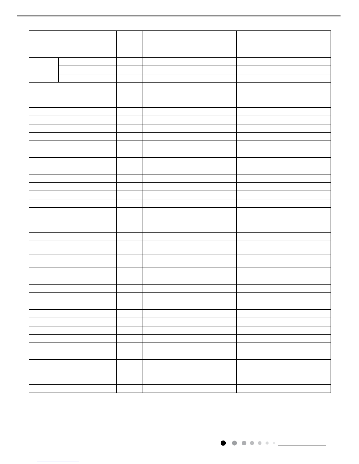
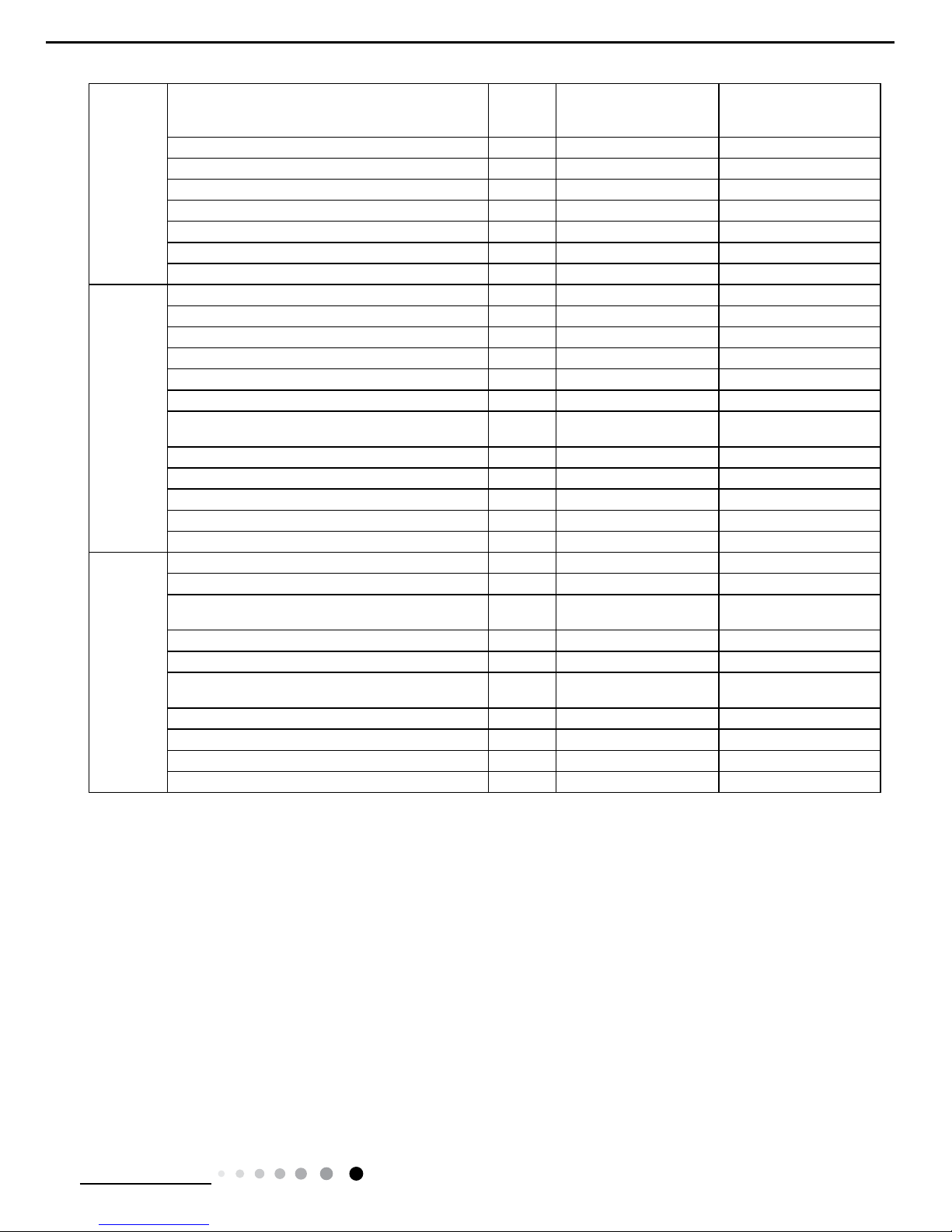
Model
GPH12AF-K3NNA7A
GPH12AF-K3NNA7D
GPH12AF-K3NNA7E
Product Code
CK01001491/CK01001492
CK010021700
CK010024400
Power
Supply
Rated Voltage V~ 220-240 220-240
Rated Frequency Hz 50 50
Phases 1 1
Cooling Capacity W 3500 3520
Heating Capacity W 3500 3520
Cooling Power Input W 1340 1345
Heating Power Input W 1200 1210
Cooling Power Current A 6.22 6.11
Heating Power Current A 5.57 5.19
Rated Input W 1550 1550
Rated Current A 7.20 7.2
Input of Heater W / /
Air Flow Volume(H/M/L) m
3
/h 450/420/390 450/420/390
Dehumidifying Volume L/h 1 1.5
EER W/W 2.61 2.62
COP W/W 2.92 2.91
SEER W/W / /
HSPF W/W / /
Application Area m
2
16-24 15-22
Climate Type T1 T1
Isolation I I
Moisture Protection IPX0 IPX0
Permissible Excessive Operating
Pressure for the Discharge Side
MPa 3.8 3.8
Permissible Excessive Operating
Pressure for the Suction Side
MPa 1 1.1
Throttling Method Capillary Capillary
Defrosting Method Auto Automatic Defrosting
Fuse A 3.15 3.15
Operation Temp
℃
16~30 16~30
Ambient Temp (Cooling)
℃
18~43 16~35
Ambient Temp (Heating)
℃
5~24 10~27
Sound Pressure Level (H/M/L) dB (A) 53/51/48 53/51/49
Sound Power Level (H/M/L) dB (A) 63/61/58 65/63/61
Dimension (WXHXD) mm 500X840X460 500X840X460
Dimension of Carton Box (LXWXH) mm 581X536X862 581X536X862
Dimension of Package (LXWXH) mm 584X539X877 584X539X877
Net Weight kg 47 47
Gross Weight kg 55 55
Refrigerant R410A R410A
Refrigerant Charge kg 0.8 0.86
7
Technical Information
Service Manual
Compressor
Compressor Manufacturer/Trademark
Zhuhai Landa Compressor
Co., Ltd/GREE
ZHUHAI LANDA
COMPRESSOR CO.,
LTD/GREE
Compressor Model QXA-C133B030gA QXA-C136B030A
Compressor Oil RB68EP/FVC68D RB68EP/FVC68D
Compressor Type Rotary Rotary
L.R.A. A 32.00 27
Compressor RLA A 5.00 5.1
Compressor Power Input W 1130 1115
Overload Protector build in UP3-02
Evaporator
Fan Type Centrifugal Centrifugal
Diameter Length(DXL) mm Φ218X109 Φ218X109
Fan Motor Speed(H/ML) r/min 800/700/610 800/700/610
Output of Fan Motor W 23 23
Fan Motor RLA A 0.10 0.25
Fan Motor Capacitor μF 2 2
Form
Aluminum Fin-copper
Tube
Aluminum Fin-copper
Tube
Pipe Diameter mm Φ7 Φ7
Row-n Gap mm 3-1.6 3-1.6
Coil Length (LXDXW) mm 363X38.1X285 363X38.1X285
Swing Motor Model MP28GA MP28GA
Output of Swing Motor W 2 2
Condenser
Fan Type Centrifugal Centrifugal
Fan Diameter mm 218 218
Form
Aluminum Fin-copper
Tube
Aluminum Fin-copper
Tube
Pipe Diameter mm Φ7 Φ7
Rows-n Gap mm 4-1.6 4-1.6
Coil Length (LXDXW) mm 350X50.8X350
350X25.4X381
350X25.4X324
Fan Motor Speed rpm 1160/910 1160/910
Output of Fan Motor W 65 65
Fan Motor RLA A 0.28 0.63
Fan Motor Capacitor μF 3 3
The above data is subject to change without notice. Please refer to the nameplate of the unit.
8
Technical Information
Service Manual
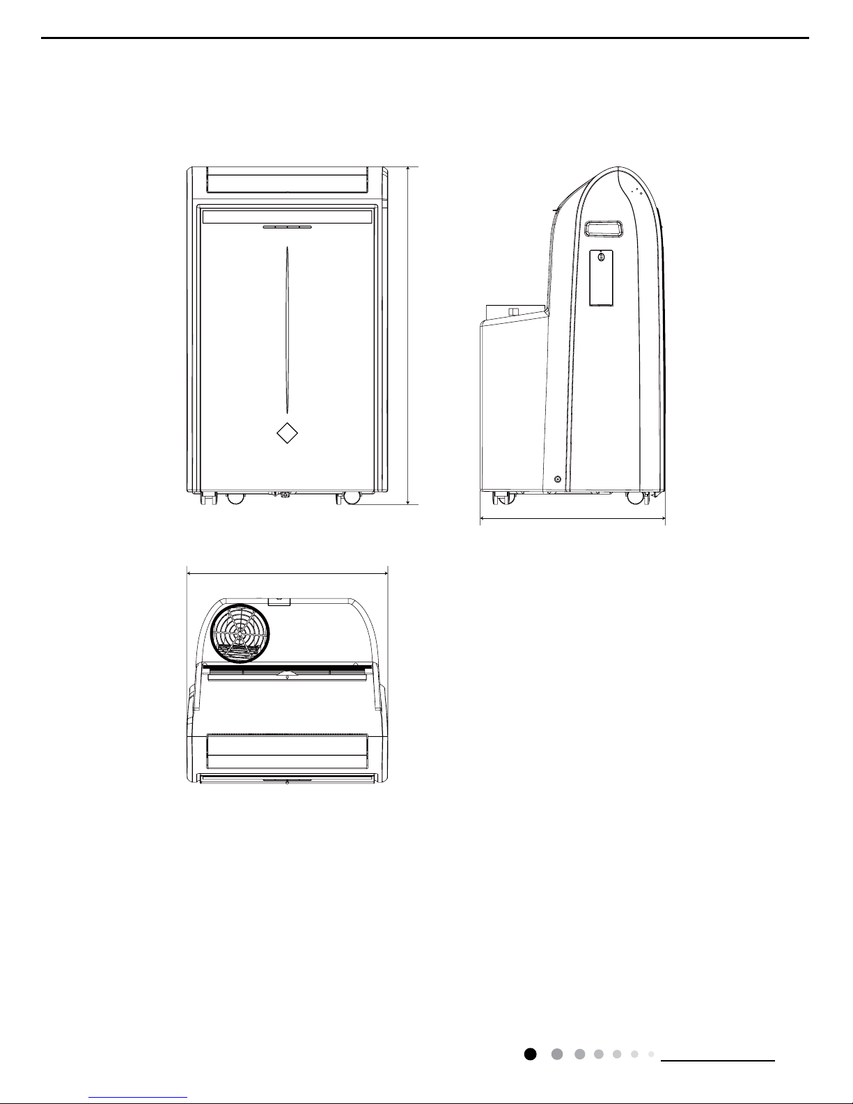
3. Outline Dimension Diagram
460
500
840
Unit: mm
9
Technical Information
Service Manual
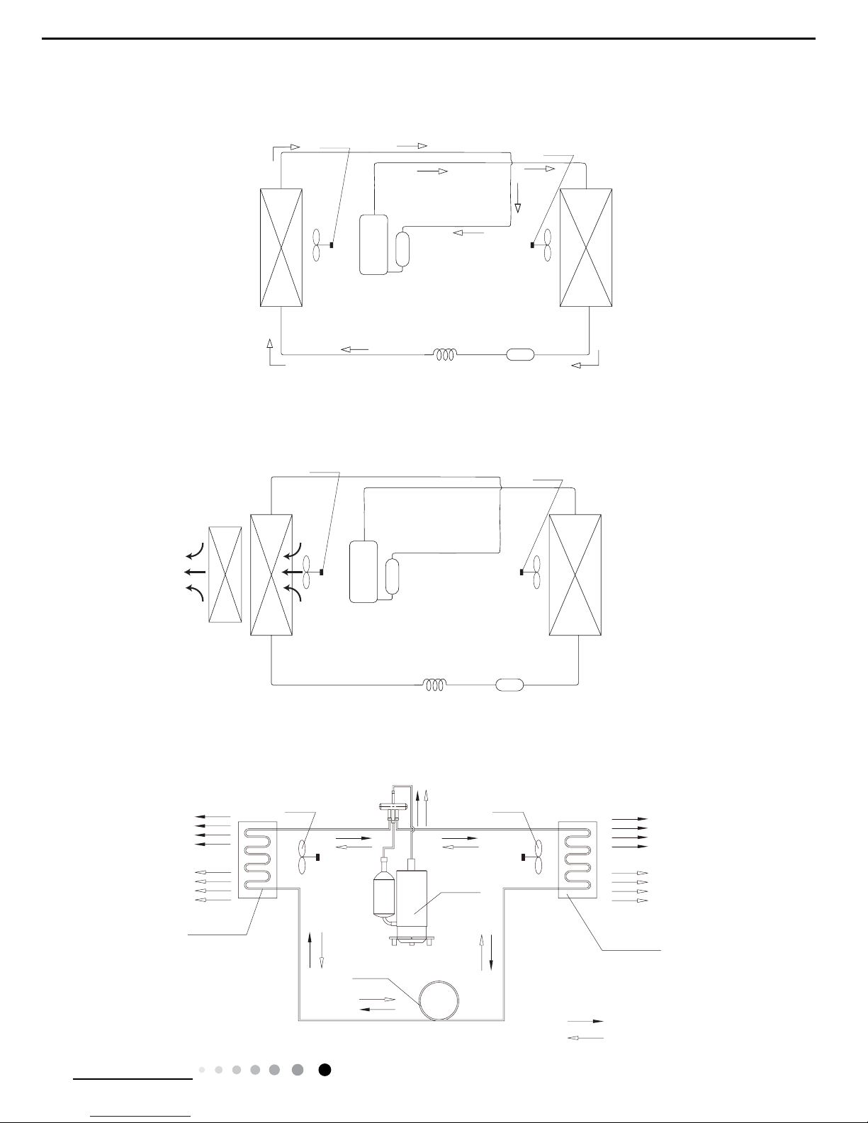
4. Refrigerant System Diagram
OUTDOOR COILS
HOT DISCHARGED AI
R
COOLED AIR
COMPRESSOR
CENTRIFUGAL FAN
CENTRIFUGAL FAN
CAPILLARY
REFRIGERANT FLOW DIRECTION
NOTES:
COOLING MODE
HEATING MODE
HOTAIR
COOLED AIR
INDOOR COILS
GPC12AF-K3NNA7A GPC12AF-K3NNA7D(CK010021500 CK010021501)
GPH12AF-K3NNA7A GPH12AF-K3NNA7D GPH12AF-K3NNA7E
GPE12AF-K3NNA7A GPE12AF-K3NNA7D
HEAT
EXCHANGE
(EVAPORATOR)
HEAT
EXCHANGE
(CONDENSER)
COMPRESSOR
CENTRIFUGAL FAN
CENTRIFUGAL FAN
Accumlator
Suction
Discharge
Capillary
Strainer
HEA
T
EXCHANG
E
(EVAPORATOR)
HEAT
EXCHANGE
(CONDENSER
)
COMPRESSOR
CENTRIFUGAL FAN
CENTRIFUGAL FAN
Accumlator
Suction
Discharge
Capillary
Strainer
10
Technical Information
Service Manual
Symbol Symbol Color Symbol Symbol Color Symbol Name
WH White GN Green COMP Compressor
YE Yellow BN Brown Grounding wire
RD Red BU Blue / /
YEGN Yellow/Green BK Black / /
VT Violet OG Orange / /
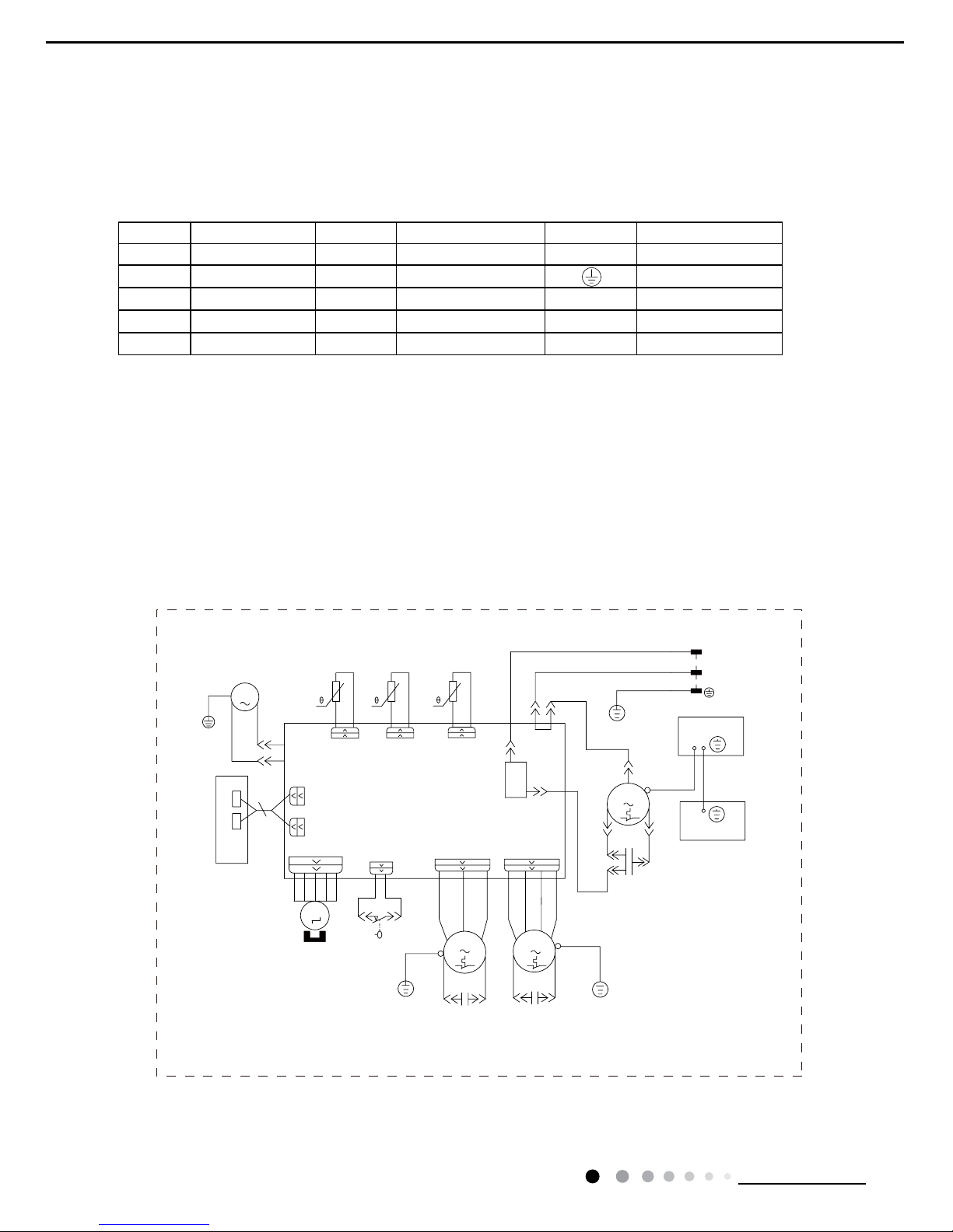
5. Electrical Part
5.1 Wiring Diagram
●Instruction
●Electric Diagram
GPC12AF-K3NNA7A GPC12AF-K3NNA7D
SWITCH
WATER LEVEL
ROOM
L
BN(BK)
N
YEGN(GN)
BU(WH)
BU
N3
S
YEGN
C
YE
C1
K201
L
COMP
AP1
N1
WATER1(WATER)
DISP2
RD
FAN
RD
YE
BK
WH
BU
DISP1
BU
SA
NC
COM
WH
BK
HIGH-WP
RD
DISP2
ROOM TEMP.
DISP1
AP2
RT1
WATER MOTOR
M4
YEGN
M1
BN
MOTOR
UP FAN
BN
RD
RD
C2
C3
DOWN FAN
MOTOR
YEGN
BU WHBK
OFAN
RT2
TUBE
SENSOR SENSOR
TUBE TEMP.
PE
SWING
M3
STEPPING
MOTOR
M2
PE
PE
UNDERPROP
ELECTRIC BOX
PE
YEGN
PE
POWER
PE
YEGN
OUTTUBE TEMP.
SENSOR
OUTTUBE
RT3
COMP.
R(M)
COMP.
MOTOR
11
Technical Information
Service Manual
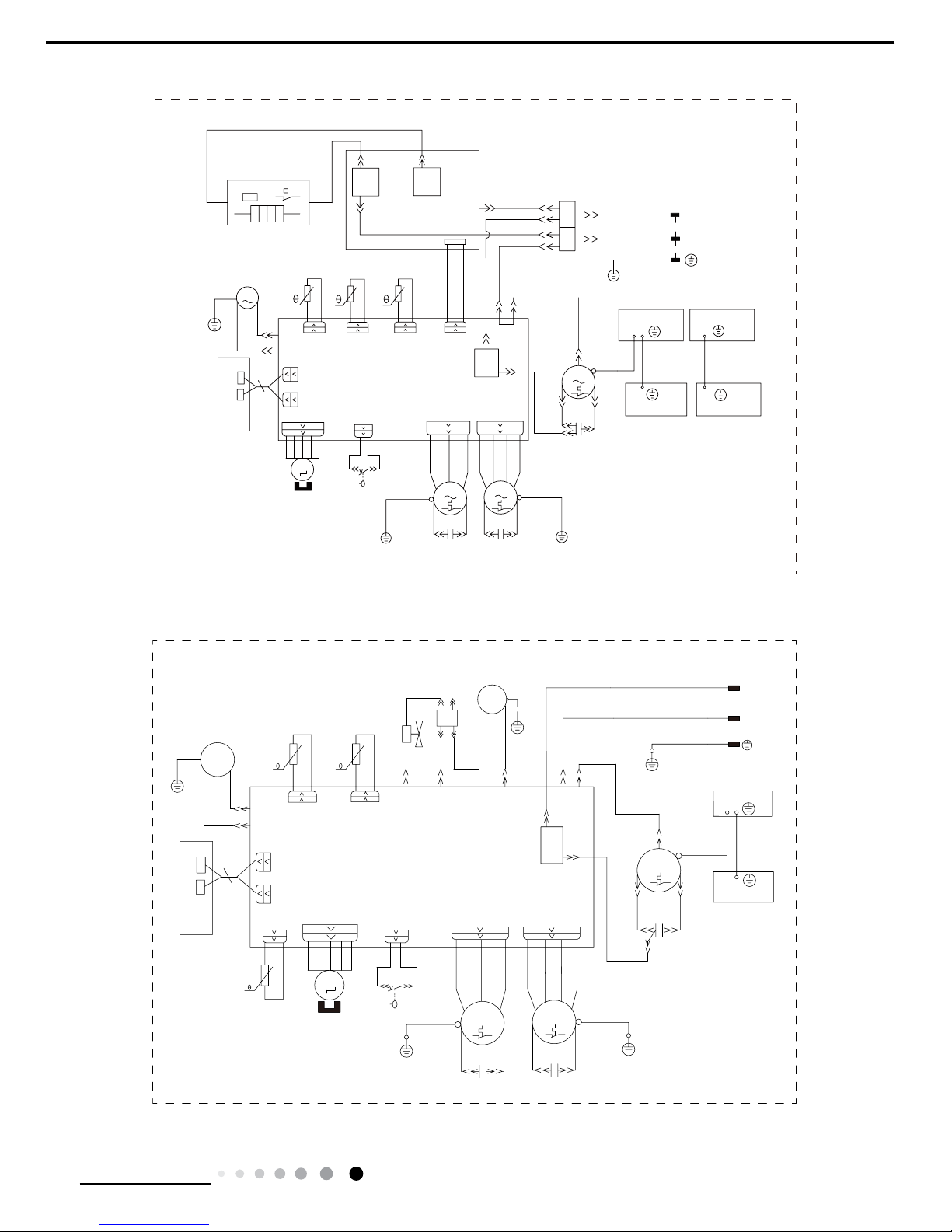
GPE12AF-K3NNA7A GPE12AF-K3NNA7D
SWITCH
WATER LEVEL
YEGN
PE
EVAPORATOR
PE
UNDERPROP2
BU
RD
BU
BN
BN
BU
AP3
CN1
HEAT-CTRL
I-HEAT-N
I-HEAT-L
K206
O-HEAT-N
K202
O-HEAT-L
ROOM
POWER
L
BN(BK)
N
YEGN(GN)
BU(WH)
N3
S
YEGN
C
YE
C1
K201
L
COMP
R(M)
AP1
N1
WATER1(WATER)
DISP2
RD
FAN
RD
YE
BK
WHBU
DISP1
BU
BU
SA
NC
COM
WH
BK
HIGH-WP
RD
DISP2
ROOM TEMP.
DISP1
AP2
RT1
WATER MOTOR
M4
YEGN
M1
BN
MOTOR
UP FAN
BN
RD
RD
C2
C3
DOWN FAN
MOTOR
YEGN
BUWHBK
OFAN
RT2
TUBE
SENSOR
SENSOR
TUBE TEMP.
PE
SWING
STEPPING
MOTOR
M2
PE
PE
UNDERPROP1
ELECTRIC BOX
PE
YEGN
PE
YEGN
PE
HEATER
TERMINAL
BLOCK
OUTTUBE TEMP.
SENSOR
OUTTUBE
RT3
COMP.
M3
1
XT
2
EH
ST
FUT
COMP.
MOTOR
These wiring diagrams are subject to change without notice; please refer to the one supplied with the unit.
GPH12AF-K3NNA7A GPH12AF-K3NNA7D GPH12AF-K3NNA7E
4YV
M3
PE
W8
YEGN
PE
ELECTRIC BOX
UNDERPROP
PE
PE
M2
~
MOTOR
STEPPING
SWING
PE
PIPE TEMP.
SENSORSENSOR
TUBE
RT2
OFAN
BK
WHBU
N3
YEGN
MOTOR
DOWN FAN
C3:3uF
C2:2uF
RD
RD
BN
UP FAN
MOTOR
BN
~
M1
YEGN
M4
WATER MOTOR
17
RT1
PCB2
DISP1
ROOM TEMP.
DISP2
RD
W7
W6
HIGH-WP
~
BK
WH
COM
NC
SA
BU
BU
COMP.
MOTOR
DISP1
BU WH
BK
YE
RD
W4
FAN
RD
W2
DISP2
WATER
N1
PCB
R(M,V)
COMP(4)
L(3)
K201
C1
YE
W3
1
2
C(T,U)
YEGN
COMP
~
S(W,X)
W5
N3
W1
BU(WH)
YEGN(GN)
N
BN(BK)
POWER
ROOM
L
N2
N2
~
WATER PUMP
M5
4V
XT
W9
VT
VT
VT
RT3
OUTTUBE
SENSOR
PIPE TEMP.
BUBN
PE
PE
YEGN
YEGN
W10
12
Technical Information
Service Manual
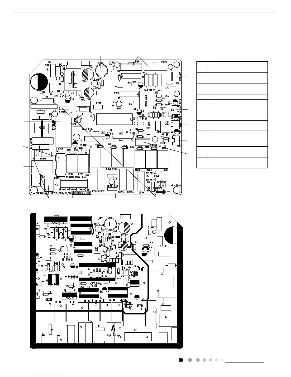
5.2 PCB Printed Diagram
(1)Silk screen on main board
7
5
6
9
4
3
2
1
15
11
10
8
13
12
14
No.Name
1connect neutral wire
2piezoresistance
3Fuse
4drive replay of compressor
5buzzer
6interface of display board
7
interface of high-level detection
switch
8
terminal of outdoor t ube
temperature sensor
9
terminal of ambient
temperature
sensor
10
terminal of tube temperatur
e
sensor
11 interface of swing motor
12 interface of draw water motor
13 interface of outdoor fan
14 interface of 4-way valve
15 interface of fan
● Top view
● Bottom view
13
Technical Information
Service Manual
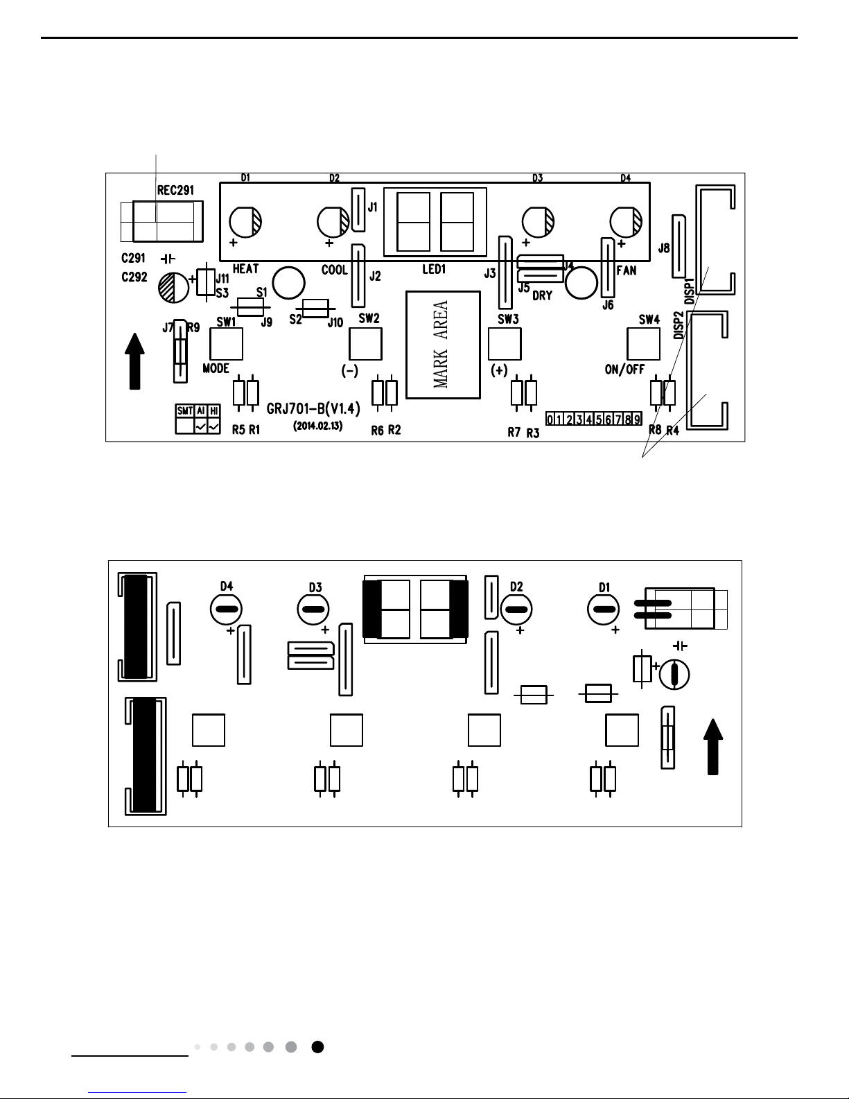
(2)Silk screen on display board
● Top view
● Bottom view
receiving head
connect with main baor
d
14
Technical Information
Service Manual
6. Function and Control
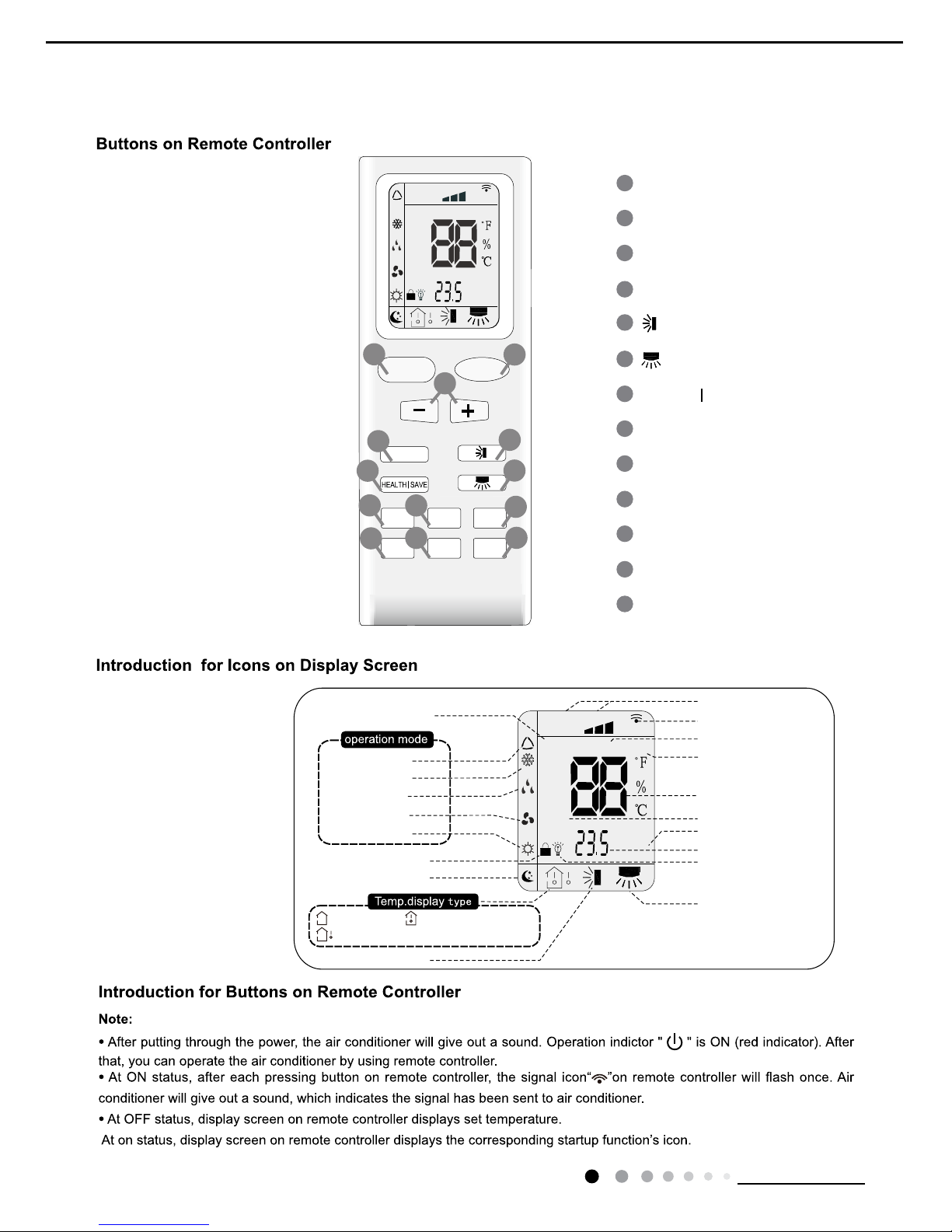
6.1 Remote Controller Introduction
ON/OFF Button
2
3
1
5
6
4
9
10
8
12
13
11
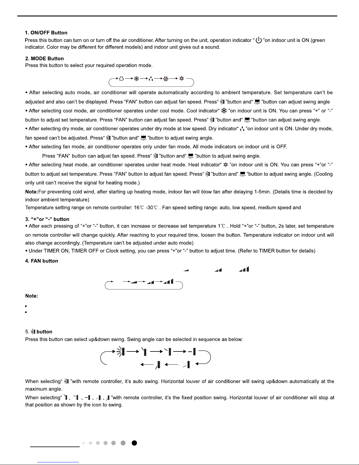
MODE Button
+/- Button
X-FAN Button
TEMP Button
TURBO Button
SLEEP Button
LIGHT Button
Button
HEALTH SAVE Button
7
Button
TIMER Button
FAN Button
FAN
AUTO
OPER
HEALTH
AIR
FILTER
TURBO
ON/OFF
X-FAN
HOUR
HUMIDITY
ON/OFF
MODE
FAN
X-FAN
TURBO
TEMP
TIMER
SLEEP
LIGHT
2
10
7
9
12
8
3
11
6
5
13
4
1
Child lock
Left&right swing
Sleep mode
Auto mode
Air mode
Cool mode
Heat mode
Fan mode
Dry mode
Up&down swing
:Indoor ambient temp.:Set temp.
:Outdoor ambient temp.
FAN
OPER
AUTO
HEALTH
AIR
FILTER
TURBO
ON/OFF
X-FAN
HOUR
HUMIDITY
TIMER ON/TIMER OFF
Set time
Light
Send signal
Health mode
X-fan
Set fan speed
Set temperature
Turbo mode
Temp. display type
Operation mode
15
Technical Information
Service Manual
AUTO COOL DRYFAN HEAT
Auto
no display
(horizontal louvers
stops at current position)
high speed.
Pressing this button can set fan speed circularly as: auto (AUTO),low( ),medium( ), high( ).
Under
AUTO Speed,IDU fan motor will adjust the fan speed (high, medium or low speed) according to ambient temperature.
Fan speed under dry mode is low speed.
Operation indicator
is ON.
16
Technical Information
Service Manual
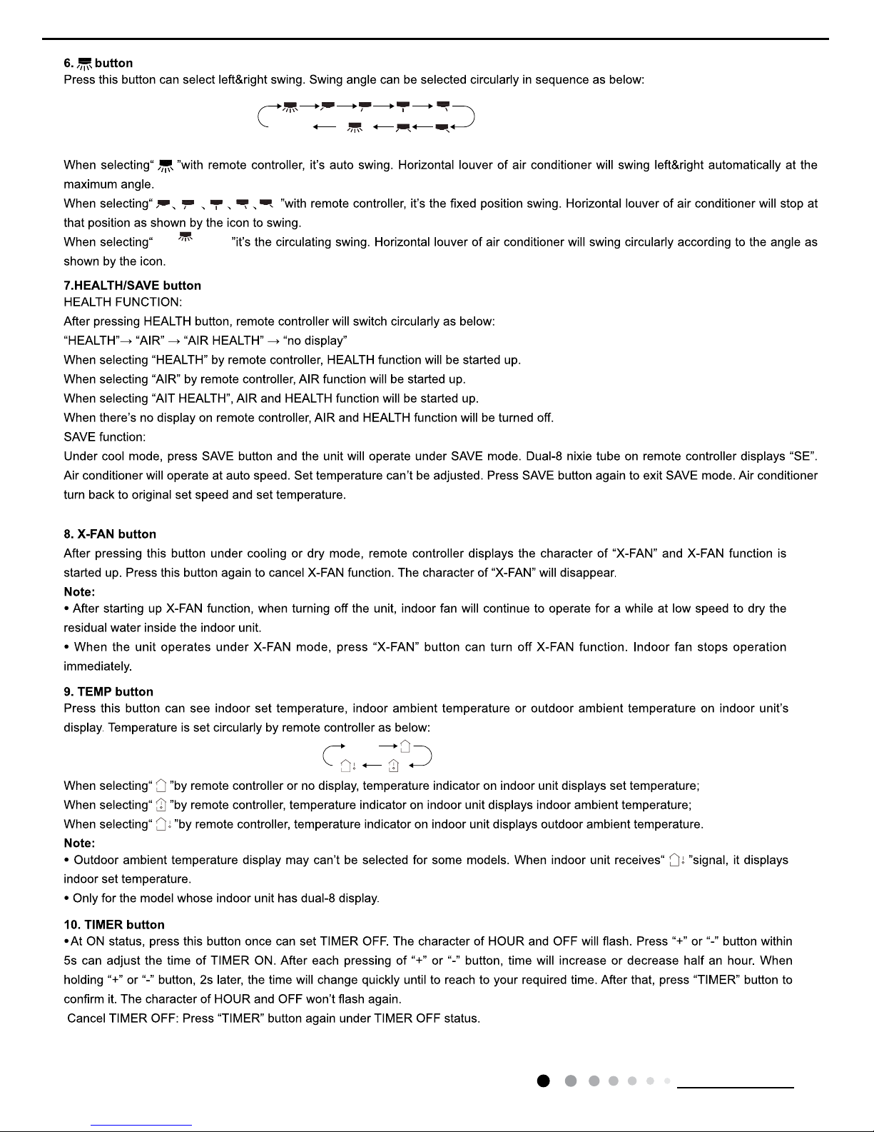
no display
no display
(swing angle is
displayed dynamically)
(horizontal louvers
stops at current position)
(swing angle is
displayed dynamically)
This function is applicable to partial of models
.
17
Technical Information
Service Manual
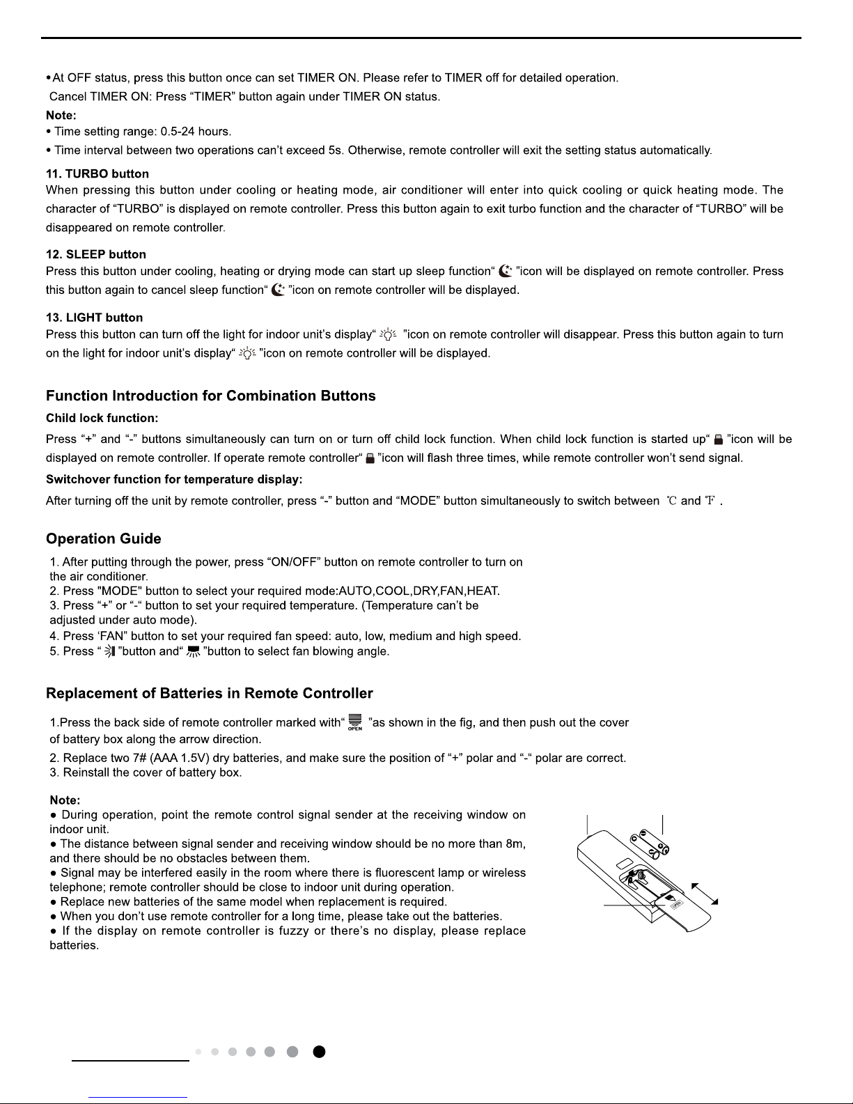
Signal sender
Battery
Cover of
battery box
Remove
Reinstall

18
Technical Information
Service Manual
6.2 Introduction of Basic Mode Function
1 Cooling mode
Cooling condition and process
When
Tamb.≥Tpreset+1ć(2), the unit operates in cooling mode. Meanwhile, compressor, draw water motor start operation. Indoor
fan operates at set fan speed. If indoor fan operates at high fan speed or middle fan speed, outdoor fan operates at high fan
speed. If
indoor fan operates at low fan speed, outdoor fan operates at low fan speed.
When
Tamb.≤Tpreset-1ć(2), compressor, outdoor fan and draw water motor stop operation, while indoor fan operates at set fan
speed.
Tp
reset-1ć(2)<Tamb.<Tpreset+1ć(2), the unit keeps original operation status.
Under this mode, 4-way valve is de-energized.
The temperature setting range is 16-30ć(61-86).
2 Dry mode
Drying condition and process
Under this mode, set temperature and ambient temperature won’t be displayed. Indoor fan operates at low fan speed. Compressor,
outdoor fan and draw water motor operates continuousl
y.
3 Heating mode
Working conditions and process for heat pump unit
When
Tamb.≤Tpreset+3ć(6), the unit operates in heating mode. Meanwhile, 4-way valve, compressor operates, and indoor fan
operates
at cold air prevention condition; if indoor fan operates at high fan speed or middle fan speed, outdoor fan operates at high fan
speed. If indoor fan operates at low fan speed, outdoor fan operates at low fan speed.
When
Tpreset+3ć(6)<Tamb.<Tpreset+5ć(10), the unit keeps original operation status,
When
Tamb.≥Tpreset+5ć(10), compressor and outdoor fan stop operation simultaneously. 4-way valve stop operation after the
compressor has stopped for 2 minutes. Indoor fan operates at blowing residual heat conditioner.
Under this mode, the temperature setting range is 16-3
0ć(61-86).
Working conditions and process for electric heating ty
pe unit
When
Tamb.≤Tpreset+3ć, the unit enters heating operation. In that case, electric heater starts up and the indoor fan operates at
setting speed;
When
Tpreset+3ć˘Tamb.˘Tpreset+5ć,the unit will keep its original status.
When
Tamb.≥Tpreset+5ć, electric heater will be turned off and indoor fan will stop after it operates at low speed for 60s.
Th
e temperature setting range is 16~30ć(61~86) under this mode.
4 Fan mode
Under this mode, set temperature and ambient temperature won’t be displayed. Indoor fan operates at set fan speed. Compressor,
outdoor fan, 4-way
valve and draw water motor operates continuously.
Under this mode, the temperature setting range is 16-3
0ć(61-86).
5
Auto mode
5.1 Under auto mode, standard cooling Tpreset=25
ć(77); standard heating Tpreset=20ć(68)
5.2 Heat pump unit: Tamb.>26
ć(79), the unit turns into auto cooling mode; Tamb.< 20ć(68), the unit turns into heating mode;
23
ć(73)≥Tamb. ≥20ć(68), if the unit operates at heating mode previously, the unit keeps heating operation status. If the unit
didn’t operate at heating mode previously, the unit will turn to dr
y mode; 26ć(79)≥Tamb. ≥24ć(74), the unit turns into auto dry
mode. For the first energization, 26
ć(79)≥Tamb. ≥20ć(68), the unit turns into drying operation mode.
5.3 Cooling only
unit: Tamb.>26ć(79), the unit turns into auto cooling mode; Tamb.< 20ć(68), the unit turns into auto fan
mode;2
0ć(68)≥Tamb. ≥23ć(73), if the unit operates at fan mode previously, the unit keeps fan mode operation status. If the unit
didn’t ope
rate at fan mode previously, the unit will turn to dry mode; 26ć(79)≥Tamb. ≥24ć(74), the unit turns into auto dry mode.
Fo
r the first energization, 26ć(79)≥Tamb. ≥20ć(68), the unit turns into drying operation mode.
6 Other function
6.1 Timer
6.1.1 General Timer
Ti
mer ON can be set at unit OFF. If selected ON time is reached, the unit will start to operate according to previous setting status. Time
setting range is 0.5-24hr in 30-minute increments.
Ti
mer OFF can be set at unit ON. If selected OFF time is reached, the unit will stop operation. Time setting range is 0.5-24hr in
30-minute increments.
6.1.2 Clock Timer
Ti
mer ON:
If
timer ON is set during operation of the unit, the unit will continue to operate. If timer ON is set at unit OFF, upon ON time reaches the
unit will start to operate according to previous setting status.
Ti
mer OFF:
If timer OFF is set at unit OFF, the sy
stem will keep standby status. If timer OFF is set at unit ON, upon OFF time reaches the unit will
stop operation.

19
Technical Information
Service Manual
6.2 Sleep function
When setting sleep function under cooling mode, Tpreset will increase
1ć (2) after 1 hours. 2 hours later, Tpreset will increase
2
ć(4) automatically. The upper limit of temperature is 30ć (86).
When setting sleep function under heating mode, Tpreset will decrease
1ć (2) after 1 hours. 2 hours later, Tpreset will decrease
2
ć (4) automatically. The lower limit of temperature is 30ć (86).
6.3 Buzzer: Upon energization or operation, the buzzer will give out sound.
6.4 Control button
ON/OFF button: turn on or turn off unit.
Mode button: the mode will be switched as below sequence:
Heat pump unit: cooling-drying-fan-heating
Cooling only unit: Cooling-drying-fan
Temperature “-“ button: If set temperature under ON status, temperature will decrease
1ć or after each pressing of this button. The
temperature can’t be set lower than 16
ć or 61. The button is invalid under auto, drying and fan mode.
Temperature “+“ button: If set temperature under ON status, temperature will increase
1ć or after each pressing of this button. The
temperature can’t be set higher than 30
ć or 86. The button is invalid under auto, drying and fan mode.
6.5 Display
6.5.1 Display of indicator
When turning of the unit, the current operation mode indicator will be displayed.(LED lamps for Cooling, Heating, Drying and Fa
n)
6.5.2 Dual-8 display
When the unit is turned on for the first time, niexie tube is defaulted to display set temperature. When the unit received the
signal of set
temperature, nixie tube display set temperature. When the unit received the signal of ambient temperature, the nixie tube disp
lays
current indoor ambient temperature.
6.5.3 Light control
When the unit is turned on for the first time, light is defaulted ON. If setting light ON by remote controller, indicator and
dual-8 nixie tube
displays current set status. If setting light OFF by remote controller, light will be turned off immediately. If there’s operat
ion for button
on panel and remote controller when setting light OFF by remote controller, indicator and dual-8 nixie tube will display set st
atus for 5s
and then turn off the light.
6.6 Auto fan speed control
6.6.1 Heating mode: under auto heating or normal heating mode, auto fan speed will operate as below mode:
When Tamb.≤Tpreset+Tcompensation-
2ć(4), indoor fan operates at high fan speed;
When Tpreset+ Tcompensation-
2ć(4)<Tamb.<Tpreset + Tcompensation, indoor fan operates at middle fan speed;
When Tamb.≥Tpreset+Tcompensation, indoor fan operates at low speed;
6.6.2 Cooling mode: under auto cooling or normal cooling mode, auto fan speed will operate as below mode:
When Tamb.≥Tpreset+ Tcompensation+
2ć(4), indoor fan operates at high fan speed;
When Tpreset+ Tcompensation<Tamb.<Tpreset + Tcompensation +
2ć(4), indoor fan operates at middle fan speed;
When Tamb.≤Tpreset+Tcompensation, indoor fan operates at low speed;
Auto fan under fan mode is as the same of cooling mode;
6.7 Power-off memory function
Memory content: mode, light, set temperature, set fan speed, swing. When power failure, the unit will operate at previous oper
ation
status automatically after power recovered.
6.8 Swing motor control
After energization, the swing blade will rotate to OFF position. If swing function hasn’t been set after turning on unit, the
swing blade
will rotate to ON position. If swing function has been set when turning on unit, swing blade will rotate to-and-fro.
6.9 X-FAN control mode
X-FAN function can be set under cooling and dry mode (X-FAN function is unavailable under auto, heating and fan mode)
7 Protection function
7.1.1 Water overflow protection
Buzzer will give out sound for 8 times for warning. The complete unit will stop operation. Error code H8 is displayed and heat
ing
indicator OFF 3s and blinks 8 times.
7.2 Malfunction of indoor ambient temp sensor
“Dual 8” nixie tube displays F1, LED lamp for cooling blinks once. Compressor, electric heater, draw water motor, 4-way valve
and
outdoor fan stop. Indoor fan will operate at set speed.
7.3 Malfunction of outdoor pipe temp sensor
“Dual 8” nixie tube displays F2, LED lamp for cooling blinks twice. Compressor, electric heater, draw water motor, 4-way valve
and
outdoor fan stop. Indoor fan will operate at set speed.
7.4 Freeze prevention protection
Under freeze prevention protection, compressor, outdoor fan and draw water motor stop operation. Indoor fan operates at set fa
n
speed.
7.5 Compressor protection
Compressor can be restarted only after 3 minutes delayed.
 Loading...