

Gree GPC10AN-K5NNA1A, GPH12AN-K5NNA1A, GPC12AN-K5NNA1A Service Manual

Change for life
Service Manual
Models:
GPC10AN-K5NNA1A
GPC12AN-K5NNA1A
GPH12AN-K5NNA1A
(Refrigerant R290)
GREE ELECTRIC APPLIANCES, INC. OF ZHUHAI

Table of Contents
Service Manual
Part
1. Summary
2. Specications
: Technical Information
Ⅰ
...........................................................................................................16
.................................................................................................17
3. Outline Dimension Diagram
4. Refrigerant System Diagram
5. Electrical Part
5.1 Wiring Diagram ..................................................................................................23
5.2 PCB Printed Diagram ......................................................................................... 25
6. Function and Control
6.1 Introduction of control panel ............................................................................... 27
6.2 Remote Controller Introduction ..........................................................................29
6.3 Introduction of Basic Mode Function .................................................................. 33
Part
: Installation and Maintenance
Ⅱ
..................................................................................................23
.................................................................................. 27
................................................................... 16
.................................................................... 21
..................................................................22
..................................................35
7.Notes Maintenance Safety Precautions:
8. Installation Precaution
9. Install
9.1 Install Power cord Hooks ...................................................................................43
9.2 Removing Collected Water ................................................................................43
10. Maintenance
10.1 Error Code ........................................................................................................53
10.2 Malfunction Detection Flowchart ...................................................................... 55
10.3 Maintenance Method for Common Malfunction ...............................................59
...................................................................................................................43
.................................................................................................. 53
11. Exploded View and Parts List
12. Removal Procedure
Appendix:
Appendix 1: Reference Sheet of Celsius and Fahrenheit ........................................77
............................................................................................................... 77
............................................................................... 41
.............................................................. 61
..................................................................................67
.......................................... 35
Appendix 2: List of Resistance for Temperature Sensor ..........................................78
Table of Contents
Service Manual
ATTENTION
Abbreviations Used Within this Manual:
Abbreviation Clear Words
OFDN Oxygen free and dry nitrogen
PPE Personnel protective equipment
LFL Lower ammability level
UFL Upper ammability level
HC Hydrocarbon
INTRODUCTION
Please read this manual carefully before installing and operating the GREE Hydrocarbon Air– Conditioner unit.
Careless installation and operation could cause severe injuries to operators, workers and damage to the air-conditioner unit
itself.
Keep this manual in a location for easy access as it is needed for reference during installation, maintenance, service and
operation of the unit.
This manual does not cover all aspects of installation, maintenance and service of the chiller units; if additional information is
needed, contact the GREE Costumer Service or Sales Ofce.
Technical Information
General Information
Warning and cautions appear at appropriate locations throughout this manual book.
1
Service Manual
Notices
General Safety Instructions
Please pay careful attention to these safety instructions, to avoid risks to people and property. Before starting work on maintenance
read this manual thoroughly and pay particular attention to the relevant chapters.
Regardless of further requirements of the country, in which the equipment will be installed: assembly, rst start up, technical service,
maintenance and repair and as well as dismantling and disposal have to be carried out by authorised personnel only.
During every operation strictly follow the instructions within this manual. Pay attention to the specific rules of air conditioning,
electrics and refrigerant handling of the country within which the equipment is installed.
Key sections and/or sentences are highlighted with specic icons and symbols to the right side of the page. Please pay particular
attention to this information.
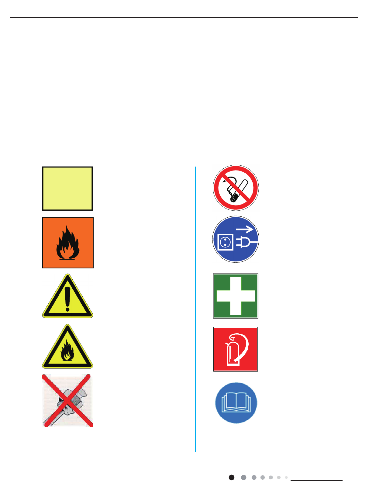
The Symbols Used in this Manual are as Follows
This is a specific
remark and
points out the
importance of a
specific section
Information window highlighting
important content of the specic
section or additional information
to consider.
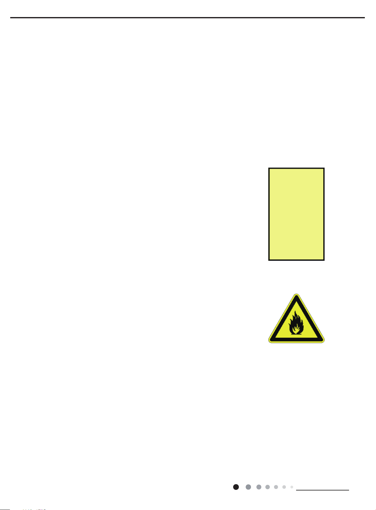
This sign will indicate that you are
handling a ammable substance
and the surrounding environment
can possibly contain it.
This is a general warning sign.
The Label is used to indicate that
the ammable refrigerant is
present within the application and
service equipment.
Specic bans!
Specic commandments!
Instructions for rst aid!
Fire protection!
Images that indicate something
what you should strictly avoid.
2
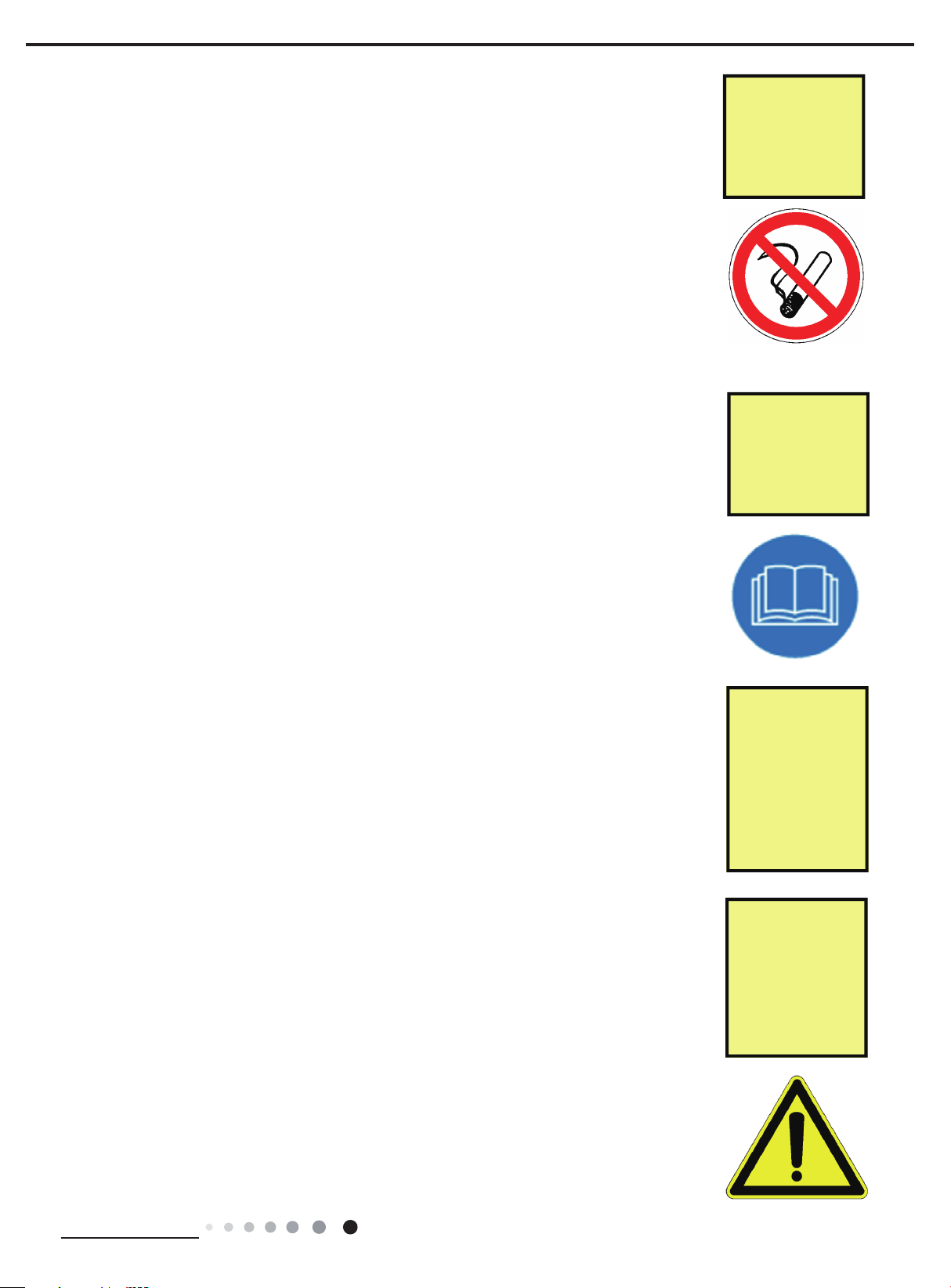
Carefully read the
instructions!
Technical Information
Service Manual
Having a
malfunction
while
commissioning,
immediately
disconnect the
system from
mains!
Working on components with safety-relevant functions jeopardise the safe operation of the
installation. In case it is necessary to replace components, only use approved parts from GREE
Electric, the Original Equipment Manufacturer(OEM) or Gree released or authorised components.
The system contains the refrigerant R-290 (propane). This condition requires special safety
precautions to be observed. While working on the system, the presence of any kind of ignition
sources (e.g. sparks, open flames, hot surfaces, static electricity) are strictly prohibited. At the
installation site, no matter what kind of activities are executed, smoking is strictly prohibited!
Likewise, ensure the installation site is well ventilated. For further details as far as it concerns the
handling of the refrigerant R-290 (propane) .
Do not charge the system with any refrigerant which is not R-290! Do not mix any refrigerants!
Before filling the system, ensure that there is no air (or other non-condensable gases such as
nitrogen) left in the system, otherwise there is severe danger of damage to the system caused by
excessive high pressure.
After charging the system with refrigerant, carefully examine and conrm the tightness by the use
of an appropriate electronic leak detector!
The Symbols Used in this Manual are as Follows
Electric operations (installation, repair, modication, maintenance, adjustment) have to be fullled
by trained and authorised personnel only. When dealing with electrical issues, the specific
rules of the country within which the equipment is installed must be followed, in addition to the
instructions within this manual.
ONLY original
GREE (OEM)
spare-parts are
permitted for
Service and Re-
pair!
Proceed
according the
manuals
Instructions!
When working on the equipment or parts of it, the system has to be deenergised (by master
switch, circuit breaker or separate cut-out) and made safe against restart of the system. Do not
reconnect the system to the electric circuit until all work is done and all connections are tested.
If handled unsafely or unprofessionally, severe electric shocks can occur. Consider the wiring
diagram and follow the instructions of this manual very carefully whilst working on electrical parts.
Wrong connections or incorrect grounding may lead to severe injuries and mortal danger.
Ground the system according to the particular requirements of the country within which the
equipment is installed.
Connect all the wires properly and durably. Loose cables may lead to overheating or re
Minimum Room Size
HC R290 is a ammable refrigerant and can form explosive mixtures in low concentrations. To
minimise the risk of re or explosion, the system must be installed in a room with a minimum oor
area.
Unless there are further requirements, standards and legislation of the country within
which the equipment is installed may apply. Any technicians that works on GREE
hydrocarbon air– conditioners must be competent in the safe handling of flammable
refrigerants, in addition to being in possession of knowledge and skills to maintain best
refrigeration installation and servicing practices.
There are already training activities in place for engineers, technicians and sales staff
to provide professional knowledge and skills for the handling of HC refrigerants and
refrigeration systems operating with HCs.
Pay attention to
the room size for
indoor unit
installation!
For specific information refer
page XXX of this
manual.
Get your Best
Practices
knowledge and
skills update for
HC refrigerants
and be
certificated for
these jobs!
“HC Refrigeration Professional” certication!
Technical Information
Get trained and have your
3
Service Manual
Basics in RAC
Knowledge of the basic SI standard units for temperature, pressure, mass, density, energy.
Understanding of the basic theory of refrigeration systems including the functions of the main components in the system (compressor,
evaporator, condenser, thermostatic expansion valves).
Understanding how to read a refrigerant ow chart and an electrical circuit diagram.
The determination of non condensable gases in the refrigeration system and how to eliminate them.
The importance of the use of oxygen free dry nitrogen (OFDN) for system ushing, leak test and strength test.
The elimination of humidity from the refrigeration system and how to recover or vent HC refrigerant from a system.
Usage of tables and diagrams (log p/h diagram, saturation tables of a refrigerant, diagram of a single compression refrigeration cycle)
and interpretation of these tables and diagrams.
Knowledge of the basic operation of the following components in a refrigeration system and their role and importance for refrigerant
leakage prevention and identication:
· Temperature and pressure controls
· Sight class and moisture indicators
· Defrost controls, reverse cycle operation
· System protectors
· Measuring devices such as the pressure gauge manifold
· Thermometer
· Leak detector
· Refrigerant charging devices
· Vacuum pump
· Oxygen free dry nitrogen cylinder and pressure regulator
Fault nding – analysis and repair.
· Knowledge of ammable refrigerants
· Risk analysis for the application of ammable refrigerant and properties of
ammable refrigerants
· Electrical circuit assessment and repair
Read More!
SAFETY CODE
OF PRACTICE
FOR REFRIGE-
RATING SYS-
TEMS
UTILISING A2 &
A3 REFRIGE-
RANTS
ISBN
1 872719 15 5
Checks before putting in operation, after a long period of
nonuse, after maintenance or repair intervention or during
operation.
Carry out a pressure and leak test to check the strength and the tightness of the system.
Usage of a vacuum pump.
Evacuation of the system to remove air and moisture according to standard practice.
Checks for Leakage
Knowledge of potential leakage points of refrigeration, air-conditioning and heat pump equipment. Making a visual and manual
inspection of the whole system.
Carry out a check for leakage of the system using an indirect method and/or one of the direct methods.
Direct leak detection methods:
1. Fixed leakage detection systems
2. Portable electronic gas detectors
3. Ultraviolet (UV) indication uids
4. Weak soapy water solution (bubble test) also in combination with OFDN
5. New installation tightness test for leakage detection procedure e.g. H2/N2
6. Operational system tightness test for leakage detection procedure
Indirect refrigerant detection methods:
1. Visual
2. Manual checks
4
Technical Information
Service Manual
Use of portable measuring devices such as pressure gauges, thermometers and multimeters for measuring Volt/Amp/Ohm in the context of indirect methods for leakage
checking and interpretation of the measured parameters. It is very important to make
use of an electronic gas detection device. Take care that the electronic gas detector
is designed and certificated for the use with flammable refrigerants. Additionally, the
electronic HC gas detector must be part of the Personnel Protective Equipment (PPE)
of the technician because if this device is operational in the work area it will warn by
detection and signalling if HC refrigerant is in the atmosphere.
The use of OFDN
is important and
the HC gas de-
tector is indeed a
personnel pro-
tection device
(PPE)!
Handling of the refrigerant during installation, maintenance, servicing or recovery or
venting
Usage of scales to weigh refrigerant. Knowledge of requirements and procedures for handling, storage and transportation especially
of ammable refrigerants and especially of contaminated refrigerant and of oils. Safe HC refrigerant recovery and venting.
Installation, commissioning and maintenance of a compressor
The basic functioning of a compressor (including capacity control and lubricating system) and risks of refrigerant leakage to its
operation. Installing a compressor properly, including control and safety equipment. Adjusting the safety and control switches.
Checking the oil return system. Start up and shut down a compressor and checking the good working conditions
of the compressor, including by making measurements during operation of compressor.
Installation, commissioning and maintenance of condensers
The basic functioning of a condenser. Installing a condenser properly, including control and safety
equipment. Adjusting the safety and control switches. Checking the hot-gas and liquid lines in
correct positions. Start up and shut down a condenser and check the good working conditions,
including by making measurements during operation. Checking the surface of the condenser.
Methods for condenser surface cleaning and ns adjustments.
Installation, commissioning and maintenance of evaporators
The basic functioning of an evaporator (including defrosting system). Installation of an evaporator
including control and safety equipment. Adjusting the safety and control switches. Checking the
liquid and suction pipelines in the correct position and checking the hot gas defrost pipeline.
Start up and shut down an evaporator and check the good working of the evaporator, including
by making measurements during operation. Functional checking of the reverse cycling control
device. Checking the surface of the evaporator. Methods for evaporator surface cleaning and ns
adjustments.
Piping
Professional brazing is another key component for safe and state of the art HC system
installation and servicing. Brazing leak free joints on metallic tubes and pipes that can be
used in refrigeration, air-conditioning or heat pump systems. Make/check pipe and component
supports and vibration elimination. Knowledge about the designing and dimensioning of the
different refrigeration system section pipes including risers. The behaviour of lubricants within the
refrigeration system and the inuences of the dimensioning of pipe work in relation to lubricants.
Develop strategies to minimise mechanical connections like aring or anges and to provide a
sealed (hermetic) system.
Preventive
maintenance will
improve the sys-
tem efficiency
Regular
professional
brazing
experience is an
important pre-
condition for the
work with
hydrocarbon
refrigerants!
Technical Information
5
Service Manual
HC R290 Refrigerant Lssues
Please notice that the unit is filled with propane. Details to this refrigerant are found in chapter “refrigerant”. Propane is highly
ammable and leads to explosion under certain conditions. Inappropriate treatment of the unit involves the risk of severe damages
of people and material.
Basics
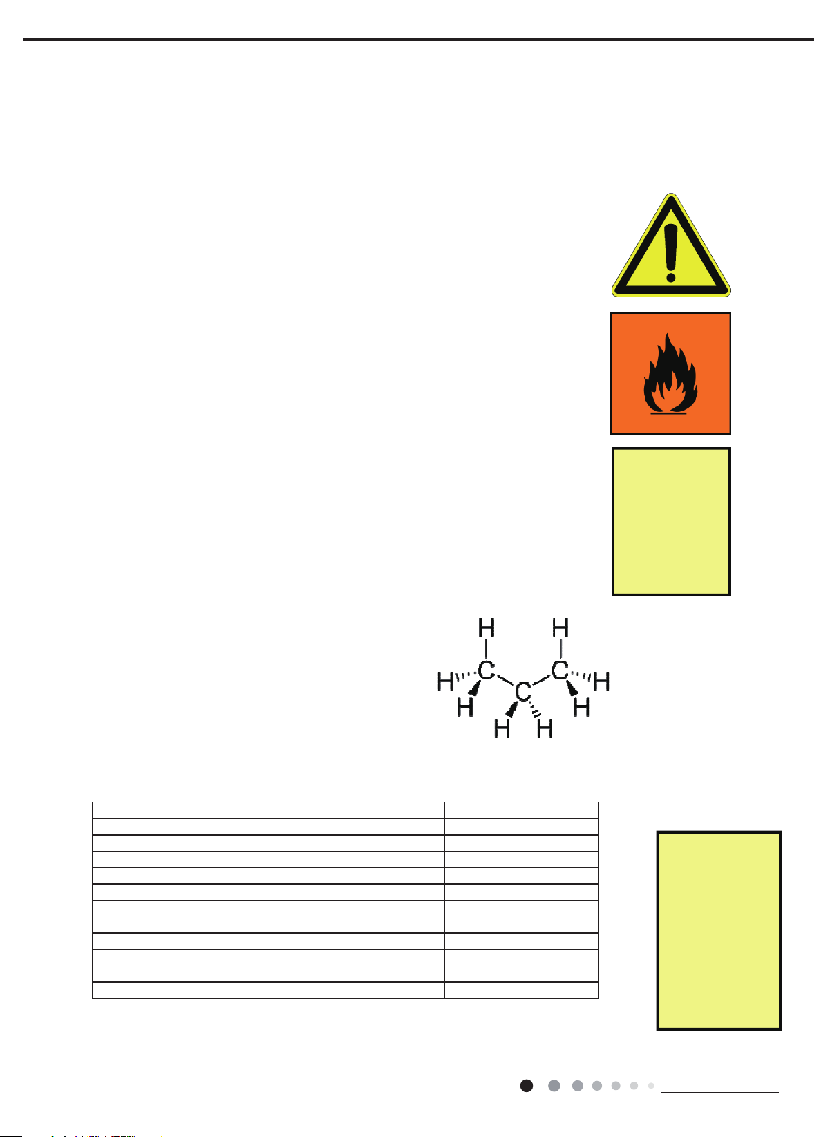
HC R-290 (propane) is an odourless and colourless gas of the group of hydrocarbons.
HC R-290 is heavier than air and at high concentrations can cause
narcotic effects and eventually asphyxiation.
R-290 is highly ammable within the range of 2,1% and 9,5% by volume, or 38
g/m3 to 170 g/m3 in air. The auto-ignition temperature is about 470°C.
Since R-290 is an odourless and colourless gas, it is difcult to perceive that it is
present (as with most other refrigerants).
Propane is often used as a fuel such as for heating or barbecues. However, for
use on refrigeration systems, fuel-grade propane is not suitable since it contains
high levels of impurities, which would damage the refrigeration system and may
not provide the desired refrigerating capacity or efciency.
The structural formula of HC R-290 (propane)
Important R efrigerant Properties and
Parameters:
Molecular formula C3H8
Melting point [°C] -188
Boiling point under atmospheric pressure [°C] -42
Molar mass [g mol -1] 44,10
Critical temperature [ °C] 96,8
Critical pressure [bar] 42
Practical limit [g/m3 ] 8
Lower ammability level LFL [g/m3 ] 38
Lower ammability level LFL [ %] 2,1
Upper ammability level UFL [ g/m3] 171
Upper ammability level UFL [ %] 9,5
Ignition temperature [ °C] 470
HC R-290 refrigerant has a high
grade of purity.
Propane as a
cooking gas is
not useful for
refrigeration
purpose!
Read More!
Guidlines for the
safe use of hydro-
carbon refrige-
rants
GIZ—PROKLIMA
http://www.gtz.de/
proklima
6
Technical Information
Service Manual
Refrigerant
Flammability
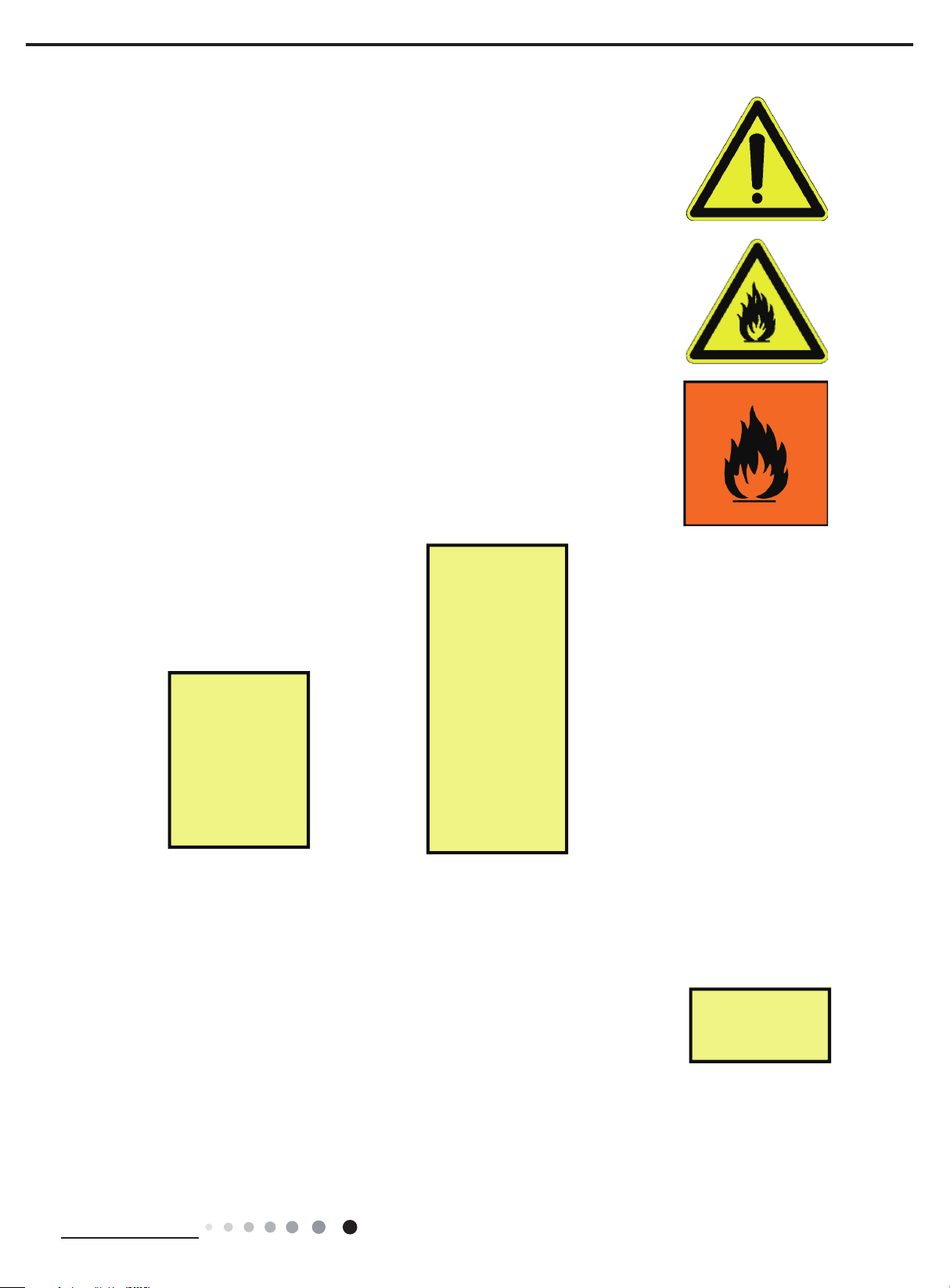
Three components are needed simultaneously for causing re:
1. Oxygen
2. Ignition source
3. The ammable concentration of HC
For ignition, the concentration of HC in air has to be between the lower and upper
ammable limits. If the concentration is below the lower ammability limit (LFL) of about
2% by volume in air, there is not enough HC for combustion. If the concentration is
above the upper ammability limit (UFL) of about 10% there is insufcient oxygen for
combustion.
2 % 10 %
HC R-290
Possible ignition sources are:
1. A flame, for example from brazing torch, halide torch leak lamp, match or
lighter, cigarette
2. A spark from an electrical component
3. Static electricity
4. Hot surfaces
By way of illustration please compare to the schematic view:
Safety Data
Hazard Identication
· Extremely ammable (F+).
· Readily forms an explosive air-vapour mixture at ambient temperatures.
· Vapour is heavier than air and may travel to remote sources of ignition (e.g.
along drainage systems, into basements etc).
· Liquid releases generate large volumes of ammable vapour (approx 250:1)
· Cold burns (frostbite) will result from skin / eye contact with liquid.
· Liquid release or vapour pressure jets present a risk of serious damage to
the eyes.
· Abuse involving inhalation of high concentrations of vapour, even for short
periods, which can produce unconsciousness or may prove fatal. Inhalation
may cause irritation to the nose and throat, headache, nausea, vomiting,
dizziness and drowsiness. In poorly ventilated areas unconsciousness or
asphyxiation may result.
Oxygen 0 % to 100 %
To ignite HC R-
290, three (3)
components
must exist at the
same time at
work area
to cause the
refrigerant
burning!
1 kg of liquid HC
R-290 refrigerant
creates about
250 litres of gas
Beside the flam-
mability, most
other safety
properties are
similar to other
refrigerants!
Rely always on
best service
practices in
refrigeration!
Technical Information
7

First Aid Measures
Inhalation:
Remove the affected person to fresh air. If breathing has stopped, administer
articial respiration. Give external cardiac massage if necessary. If the person is
breathing but unconscious, place them in the recovery position. Obtain medical
assistance immediately.
Skin:
In case of cold burns: ush with water to normalize temperature. Cover the burns
with sterile dressings Do not use ointments or powders. Obtain medical assistance
immediately.
Eyes:
Cold burns should be ushed with water to normalise temperature, cover the eye
with a sterile dressing and obtain medical assistance immediately.
Service Manual
Fire Fighting Measures
HC R-290 is delivered, stored, and used at temperatures above their ash point. Avoid all naked ames, sparks, cigarettes
etc.
· In case of re, immediately alert re brigade
· Ensure an escape path is always available from any re
· If gas has ignited do not attempt to extinguish but stop gas ow and allowto burn out.
· Use water spray to cool heat-exposed containers, and to protect surroundingareas and personnel effecting the shut off
· Every precaution must be taken to keep containers cool to avoid the possibilityof a boiling liquid expanding vapour
explosion (BLEVE)
Extinguishing Media:
In case of a large re:
Release must be stopped and container cooled by water spray.
Water mist should be used to assist approach to the source of the re.
Large res should only be handled by Fire Brigade.
DO NOT USE WATER JET
Small re:
Use dry powder extinguisher
8
Technical Information
Service Manual
DO NOT USE WATER JET
Special protective equipment for re ghters:
In conned spaces use self-contained breathing apparatus
Hazardous combustion products:
Incomplete combustion may form carbon monoxide.
Accidental Release Measures
Immediate emergency action:
· Clear people away from the area to a safe place
· Do not operate electrical equipment unless “Ex”-rated
· Summon the emergency services
· Treat or refer casualties if necessary
Further action (when release is made safe):
· Extinguish all naked lights – avoid creating sparks
· Position re ghting equipment
· Cover drains and disperse vapour with water spray.
Note: vapour may collectin conned spaces.
Further actions:
· Stop release
· Use dry powder or carbon dioxide extinguishers
· Cool containers exposed to re by using water / mist spray.
Accidental Release Measures
Due to the flammability of R-290 and the risk of fire or explosion during servicing,
special safety rules must be followed during operation. In order to avoid damage for
people and property, particular requirements are listed hereafter.
Before servicing the unit, the surrounding area were the work will be done must be
clear of safety hazards to ensure safe working. Nevertheless it is required to carry out
a risk assessment in order to minimise the risk of ignition of R-290.
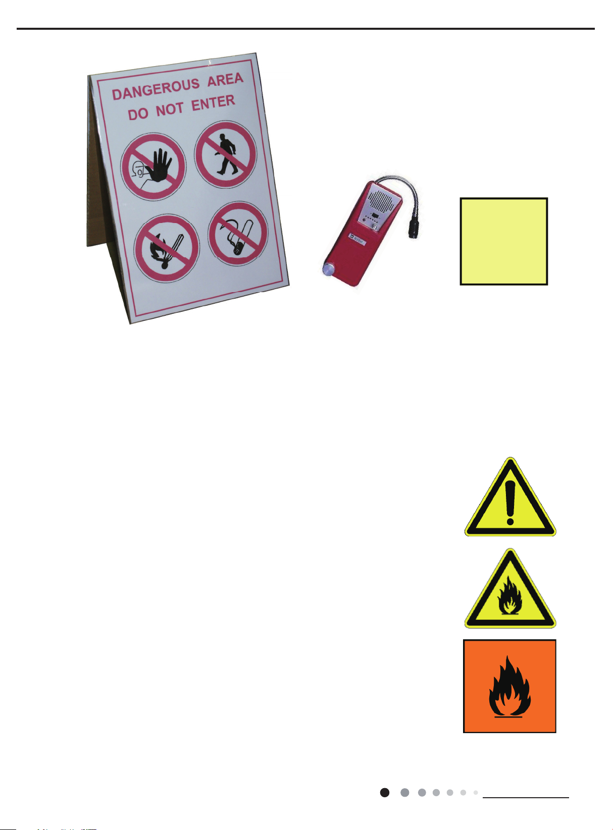
The following safety measures must be followed:
1. Any employees and other present persons must be informed about the service and the way the service is done, rst.
2. It is recommended to isolate the working environment in order to keep out any unauthorised personnel.
3. It is useful to set up signs such as „no smoking“ or „access denied“.
4. It is prohibited to store any combustible goods within the working environment.
5. Within two (2) metres radius, ignition sources are not allowed in the working area.
6. Fire extinguisher (dry powder) must be easily accessible at any time.
7. During service work, proper ventilation of the environment must be ensured.
Technical Information
9
Service Manual
The HC leak de-
tector is indeed
a Personal
Protective
Equipment
(PPE)
device!
Sign plate to protect and mark the working area.
Appropriate detectors, suitable for hydrocarbons, must be available and operational all the time. Appropriate tools and
appliances must be available and ready for operation.
Any employees need to be instructed extensively about the safety measures and the possible safety hazard.
Refrigerant Recovery
Before starting service work on the refrigerant circuit, the existing refrigerant must
be removed. When carrying out removal of the refrigerant, the following must be
considered:
· The recovery cylinder must be permitted for the use of R-290 (especially regarding the
pressure and the compatibility of the connectors and the valves).
· The recovery machine must be suitable for operation with R-290. Importantly, the
recovery machine must not itself be an ignition source.
· The lling of the recovery cylinder should be monitored closely by controlling the weight.
It is recommended to place and then to leave the cylinder on a digital scale. Pay attention
to not overfilling the cylinder. The cylinder is only allowed to be filled up to 80% of its
complete volume by liquid refrigerant.
· The pressure must be controlled in order to ensure that the permissible pressure of the
cylinder is not exceeded at any time.
· After filling, the cylinder must be marked with the mass and the type of refrigerant
recovered.
· The recovery machine should be operated until the pressure reduces to 0,3 bar
absolute pressure. R-290 is soluble to oil. This may lead to a rise of pressure because the
refrigerant vaporises from oil. It may be necessary to operate the recovery machine for a
second or even a third time.
· Small amounts of R-290 can be vented in safe manner to the environment.
· Remaining amounts of HC absorbed by the oil can be extracted from the system using
a vacuum pump in combination with an exhaust vent hose.
· A second “two way excess” recovery cylinder can be used in serial connection to act as
an oil-separator.
· After the systems‘ pump out, the system should be ushed with oxygenfree
dry nitrogen (OFDN) in order to ensure no ammable gas are inside
the system.
10
Technical Information
Service Manual
Repair of Leaks
System leaks must be immediately repaired by authorised personnel after becoming
acquainted. If they cannot be repaired immediately, the refrigerant charge should be
removed from the system until the point at which the leak can be properly repaired.
· Removing the refrigerant from the system in order to avoid an uncontrolled
discharge.
· Examine the leak source, determining the reason for the leak and carry out the
proper course of action
· Repair properly (NO „temporary repairing”)
· Based on the results of the systems’ examination, suitable measures need to be
identied in order to avoid a recurrent appearance of the leak.
· Before embarking on the repair, ensure that the refrigerant has been removed
and the system ushed with OFDN, especially if brazing is to take place
· After each intervention into a refrigeration system (repairing leaks, replacing
components, brazing) the system must be subject to a leak test and following
strength test of the system.
The use OFDN is
an important
precondition for
professional
leak repair!
1. System flush-
Regular
professional
brazing
experience is an
important pre-
condition for the
work with
hydrocarbon
refrigerants!
ing from HC
2. Inert gas brazing
3. Leak testing
4. Strength testing
5. Cleaning
(blowing)
agent
Gas Detection
While servicing the unit it is recommended for the whole period of work — before,during
and after — to monitor the gas concentration in the air within the work environment. By
monitoring the air within the work environment the danger of a possible formation of
ammable atmosphere can be detected early.
The HC leak detector is indeed
a PPE device!
Doing the monitoring, ensure that the gas detectors are suitable for hydrocarbon detection.
Never use open re or a device with an ignition source for the detection of gas or for leak
detection.
Technical Information
11
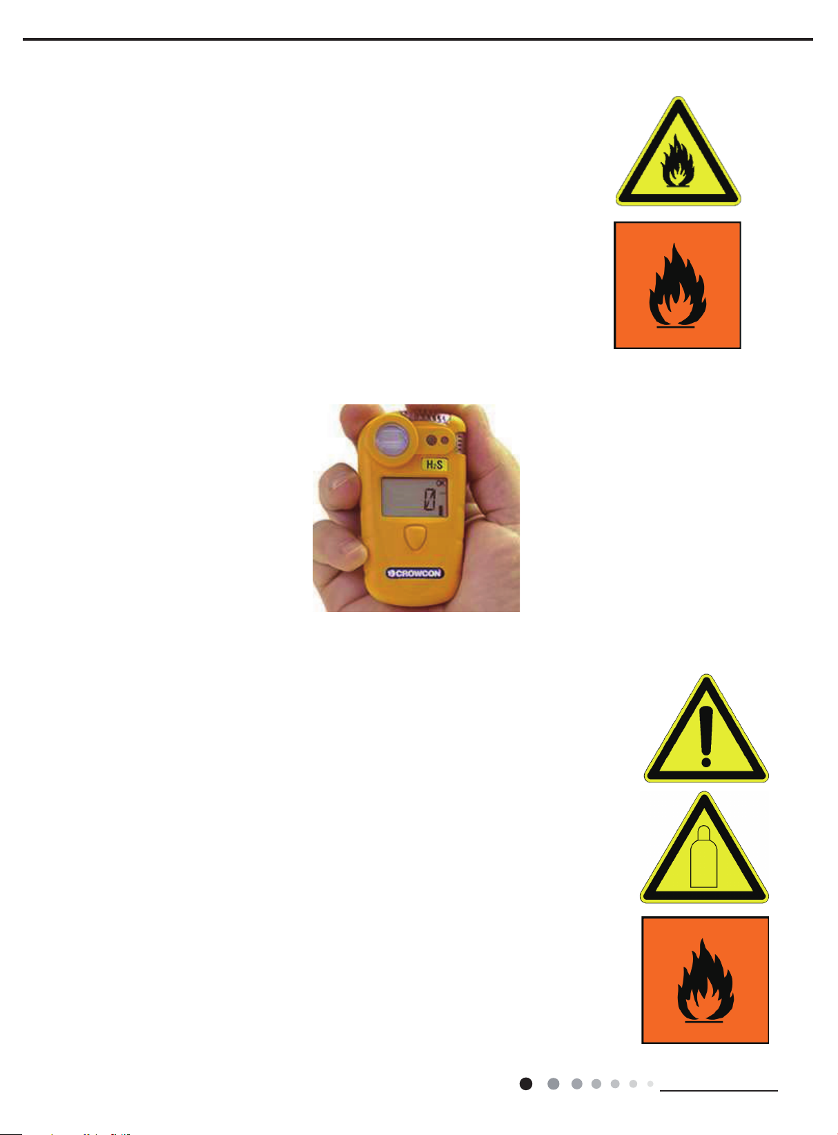
Before operation of the gas detector the instruction manual must be read carefully.
Portable HC Gas Detector
In case of any questions refer to the detector manufacturer. Furthermore ensure the
detector is correctly calibrated. Instructions for calibration can be found in the instruction
manual of the detector or upon request from the manufacturer.
A possible re-calibration must be done within an area which is free of refrigerants.
In case of a positive detection by the detector any work must be stopped immediately.
Any open ames or ignition sources must be extinguished or removed. In addition to a
suitable and approved HC gas detectors, portable gas detectors can be used.
Such a detector can be clipped to clothing or placed on the floor within the working
area. It should be switched on for the duration of the work, and set to alarm at 15% of
the lower ammability level (LFL), to warn that ammable concentration may be nearby.
In this way, technicians can be alerted whenever an inadvertent release of ammable
refrigerant occurs, and can immediately act upon the relevant emergency procedures.
Service Manual
Cylinder Handling
R-290 is available in a large variety of different cylinders which are to be distinguished
whether they are rellable or not. Most rellable cylinders are equipped with pressure relief
valves, often with own special construction of valves in order to distinguish them from the
cylinders of different refrigerants.
Often special legal requirements about the handling of ammable refrigerants exist in the
different countries. These requirements must be studied and adhered to. Principally the
following regulations in dealing with R-290 cylinders apply:
1. Do not remove or destroy ofcial stickers of the cylinder
2. Close the cylinder with a cap any time the cylinder is not used
3. Never expose the cylinder to direct heat
4. Do not repair or modify the cylinder or the cylinders‘ connections
5. Only use suitable equipment for transportation of the cylinder, even for short distances.
Never roll the cylinder across the ground.
6. Take appropriate measures in order to prevent impurities, water or oil from entering the
cylinder.
7. Should it be necessary to warm the cylinder, only use warm water or air which temperature
must not exceed 40 °C (104 °F). O pen ames or radiant heaters are not allowed at any
time.
12
Technical Information

Service Manual
8. Weigh the cylinder and compare it against the tare weight (normally stamped on the
cylinder) in order to make sure that it is empty. Pressure control is no secure method to nd
out if and how much refrigerant there is inside the cylinder.
9. For accurate charging, use a set of reliable scales with appropriate resolution (depending
on the size of system charged with refrigerant) and use the smallest size of cylinder
available.
10. For recovery of R-290, only use cylinders which are allowed to be lled with R-290.
11. Make sure that safety inspections are still valid (i.e. within date), specically with regards
to safety test certication.
12. For refillable recovery cylinders keep in mind that with recovered amounts of HC
refrigerant, oil will always be present specific amounts may remain in the cylinder after
emptying.
The storage of R-290 cylinders is controlled by regulations. These regulations take priority
over the present guidelines. Typically, such rules imply the following:
1. Cylinders should be stored in a separate area, preferably outside, otherwise in a dry, well
ventilated place far away from any ignition source.
2. Admission to storage area must only be given to authorised personnel only. Storage areas
must be labelled with “no smoking” and “no naked ames” sign.
3. Storage areas should be at ground level and never in the basement.
4. Access should be easy – exclude any obstacles.
5. Cylinders should be stored and operated only in an upright position.
6. Choose appropriate measures to prevent static charges
7. Please remember that the maximum quantity of stored refrigerant sometimes might be
regulated by national regulations.
Charging HC!
Always use the
smallest cylin-
der possible and
relay on appro-
priate accurate
and sensitive
scales
Read More!
Guidlines for the
safe use of hydro-
carbon refrige-
rants
GIZ—PROKLIMA
http://www.gtz.de/
proklima
The transport of cylinders is controlled by laws in most countries. These laws must always be regarded first before the
mentioned guidelines here. In many cases information about regulations for the transport of cylinders could be given by the
dealer of the refrigerant.
Basically the following must be regarded concerning the transport of R290 cylinders:
1. During the transportation of R290 always carry along printed information about the
refrigerant. In case of emergency these information must be easy accessible. There
are often different demands to the transporters carrying a great quantity of gas. Inform
yourself before the scheduled transport.
2. Make yourself familiar with the risks of the refrigerant and the emergency measures
in case of accident or emergency.
3. Always carry a re extinguisher during transportation with you. It should be a dry
powder re extinguisher with a capacity at least of 2 kg. Make sure that the driver is
experienced in re extinguisher operation.
4. Cylinders must be transported in an upright position and be tightly secured.
5. Make sure of a proper ventilation inside the van even though it might request a
change in the vans‘ body construction.
6. Place the security advise „ammable gas“ upon the rear side of the van.
7. Smoking or open re is strictly forbidden inside the van.
8. Do not leave cylinders in a locked van without surveillance longer than necessary.
Technical Information
13
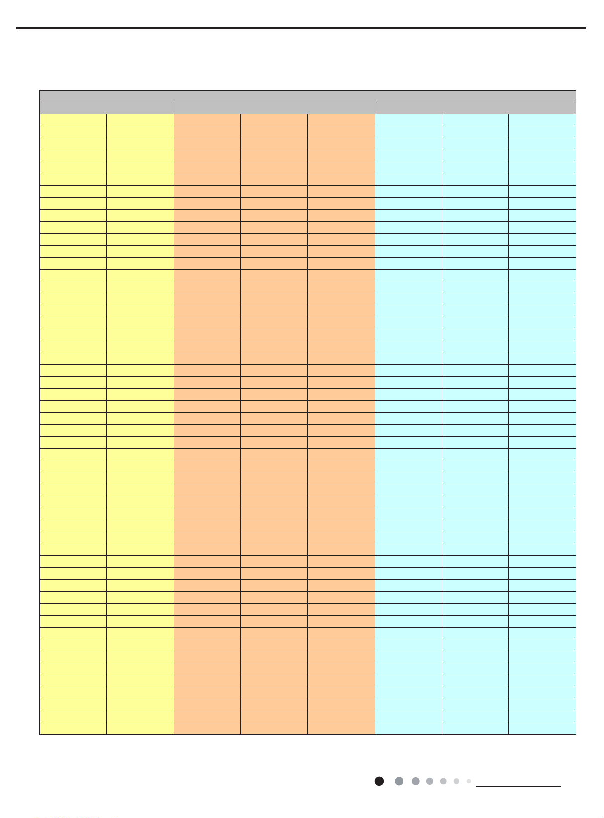
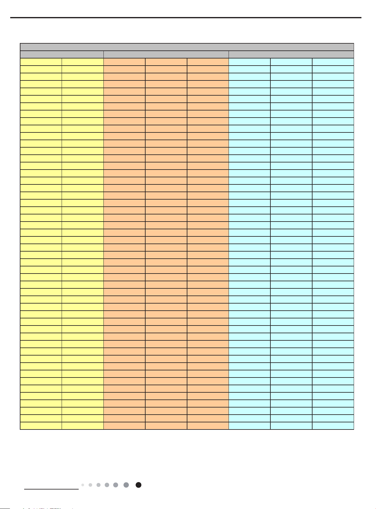
Pressure—Temperature Chart
HC Refrigerant R-290
Temperature Absolute pressure Gauge pressure
°C °F kPa bar PSI kPa(g) bar(g) PSI(g)
-40 -40 111,12 1,11 16,12 11,12 0,11 1,61
-39 -38,2 116,00 1,16 16,83 16,00 0,16 2,32
-38 -36,4 121,05 1,21 17,56 21,05 0,21 3,05
-37 -34,6 126,27 1,26 18,31 26,27 0,26 3,81
-36 -32,8 131,66 1,32 19,10 31,66 0,32 4,59
-35 -31 137,23 1,37 19,90 37,23 0,37 5,40
-34 -29,2 142,97 1,43 20,74 42,97 0,43 6,23
-33 -27,4 148,90 1,49 21,60 48,90 0,49 7,09
-32 -25,6 155,02 1,55 22,48 55,02 0,55 7,98
-31 -23,8 161,33 1,61 23,40 61,33 0,61 8,89
-30 -22 167,83 1,68 24,34 67,83 0,68 9,84
-29 -20,2 174,54 1,75 25,31 74,54 0,75 10,81
-28 -18,4 181,44 1,81 26,32 81,44 0,81 11,81
-27 -16,6 188,56 1,89 27,35 88,56 0,89 12,84
-26 -14,8 195,89 1,96 28,41 95,89 0,96 13,91
-25 -13 203,43 2,03 29,51 103,43 1,03 15,00
-24 -11,2 211,19 2,11 30,63 111,19 1,11 16,13
-23 -9,4 219,18 2,19 31,79 119,18 1,19 17,29
-22 -7,6 227,39 2,27 32,98 127,39 1,27 18,48
-21 -5,8 235,84 2,36 34,21 135,84 1,36 19,70
-20 -4 244,52 2,45 35,46 144,52 1,45 20,96
-19 -2,2 253,44 2,53 36,76 153,44 1,53 22,26
-18 -0,4 262,61 2,63 38,09 162,61 1,63 23,58
-17 1,4 272,03 2,72 39,45 172,03 1,72 24,95
-16 3,2 281,70 2,82 40,86 181,70 1,82 26,35
-15 5 291,62 2,92 42,30 191,62 1,92 27,79
-14 6,8 301,81 3,02 43,78 201,81 2,02 29,27
-13 8,6 312,27 3,12 45,29 212,27 2,12 30,79
-12 10,4 323,00 3,23 46,85 223,00 2,23 32,34
-11 12,2 334,00 3,34 48,44 234,00 2,34 33,94
-10 14 345,28 3,45 50,08 245,28 2,45 35,58
-9 15,8 356,85 3,57 51,76 256,85 2,57 37,25
-8 17,6 368,70 3,69 53,48 268,70 2,69 38,97
-7 19,4 380,85 3,81 55,24 280,85 2,81 40,73
-6 21,2 393,29 3,93 57,04 293,29 2,93 42,54
-5 23 406,04 4,06 58,89 306,04 3,06 44,39
-4 24,8 419,09 4,19 60,78 319,09 3,19 46,28
-3 26,6 432,45 4,32 62,72 332,45 3,32 48,22
-2 28,4 446,13 4,46 64,71 346,13 3,46 50,20
-1 30,2 460,13 4,60 66,74 360,13 3,60 52,23
0 32 474,46 4,74 68,82 374,46 3,74 54,31
1 33,8 489,11 4,89 70,94 389,11 3,89 56,44
2 35,6 504,10 5,04 73,11 404,10 4,04 58,61
3 37,4 519,43 5,19 75,34 419,43 4,19 60,83
4 39,2 535,10 5,35 77,61 435,10 4,35 63,11
5 41 551,12 5,51 79,93 451,12 4,51 65,43
6 42,8 567,49 5,67 82,31 467,49 4,67 67,80
7 44,6 584,22 5,84 84,74 484,22 4,84 70,23
8 46,4 601,31 6,01
9 48,2 618,77 6,19 89,75 518,77 5,19 75,24
10 50 636,60 6,37 92,33 536,60 5,37 77,83
87,21 501,31 5,01 72,71
Service Manual
14
Technical Information
Service Manual
Temperature Absolute pressure Gauge pressure
11 51,8 654,81 6,55 94,97 554,81 5,55 80,47
12 53,6 673,40 6,73 97,67 573,40 5,73 83,17
13 55,4 692,38 6,92 100,42 592,38 5,92 85,92
14 57,2 711,75 7,12 103,23 611,75 6,12 88,73
15 59 731,51 7,32 106,10 631,51 6,32 91,59
16 60,8 751,68 7,52 109,02 651,68 6,52 94,52
17 62,6 772,25 7,72 112,01 672,25 6,72 97,50
18 64,4 793,24 7,93 115,05 693,24 6,93 100,55
19 66,2 814,64 8,15 118,16 714,64 7,15 103,65
20 68 836,46 8,36 121,32 736,46 7,36 106,82
21 69,8 858,71 8,59 124,55 758,71 7,59 110,04
22 71,6 881,39 8,81 127,84 781,39 7,81 113,33
23 73,4 904,51 9,05 131,19 804,51 8,05 116,69
24 75,2 928,07 9,28 134,61 828,07 8,28 120,10
25 77 952,07 9,52 138,09 852,07 8,52 123,58
26 78,8 976,53 9,77 141,64 876,53 8,77 127,13
27 80,6 1001,45 10,01 145,25 901,45 9,01 130,75
28 82,4 1026,83 10,27 148,93 926,83 9,27 134,43
29 84,2 1052,68 10,53 152,68 952,68 9,53 138,18
30 86 1079,00 10,79 156,50 979,00 9,79 141,99
31 87,8 1105,79 11,06 160,38 1005,79 10,06 145,88
32 89,6 1133,08 11,33 164,34 1033,08 10,33 149,84
33 91,4 1160,85 11,61 168,37 1060,85 10,61 153,87
34 93,2 1189,12 11,89 172,47 1089,12 10,89 157,97
35 95 1217,88 12,18 176,64 1117,88 11,18 162,14
36 96,8 1247,16 12,47 180,89 1147,16 11,47 166,38
37 98,6 1276,94 12,77 185,21 1176,94 11,77 170,70
38 100,4 1307,24 13,07 189,60 1207,24 12,07 175,10
39 102,2 1338,07 13,38 194,07 1238,07 12,38 179,57
40 104 1369,42 13,69 198,62 1269,42 12,69 184,12
41 105,8 1401,31 14,01 203,25 1301,31 13,01 188,74
42 107,6 1433,73 14,34 207,95 1333,73 13,34 193,44
43 109,4 1466,71 14,67 212,73 1366,71 13,67 198,23
44 111,2 1500,23 15,00 217,59 1400,23 14,00 203,09
45 113 1534,31 15,34 222,54 1434,31 14,34 208,03
46 114,8 1568,96 15,69 227,56 1468,96 14,69 213,06
47 116,6 1604,18 16,04 232,67 1504,18 15,04 218,17
48 118,4 1639,97 16,40 237,86 1539,97 15,40 223,36
49 120,2 1676,34 16,76 243,14 1576,34 15,76 228,63
50 122 1713,30 17,13 248,50 1613,30 16,13 233,99
51 123,8 1750,86 17,51 253,94 1650,86 16,51 239,44
52 125,6 1789,02 17,89 259,48 1689,02 16,89 244,98
53 127,4 1827,79 18,28 265,10 1727,79 17,28 250,60
54 129,2 1867,17 18,67 270,81 1767,17 17,67 256,31
55 131 1907,17 19,07 276,62 1807,17 18,07 262,11
56 132,8 1947,80 19,48 282,51 1847,80 18,48 268,01
57 134,6 1989,07 19,89 288,49 1889,07 18,89 273,99
58 136,4 2030,98 20,31 294,57 1930,98 19,31 280,07
59 138,2 2073,54 20,74 300,75 1973,54 19,74 286,24
60 140 2116,75 21,17
HC Refrigerant R-290
307,01 2016,75 20,17 292,51
Technical Information
15
Service Manual
Part
Ⅰ
: Technical Information
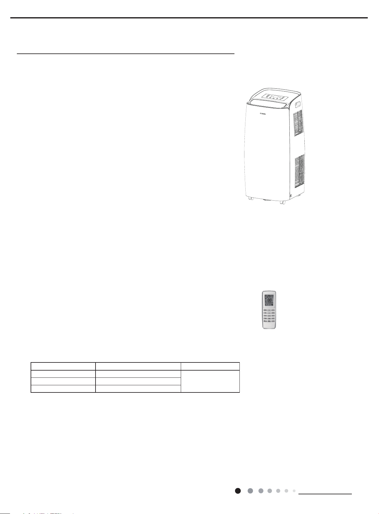
1. Summary
GPC10AN-K5NNA1A
GPC12AN-K5NNA1A
GPH12AN-K5NNA1A
Remote Controller:
YV1F9(WiFi)
Models Product Code Remote Controller
GPC12AN-K5NNA1A CK010032400/CK010032401
GPH12AN-K5NNA1A CK010031300
YV1F9(WiFi)GPC10AN-K5NNA1A CK010032300
16
Technical Information
Service Manual
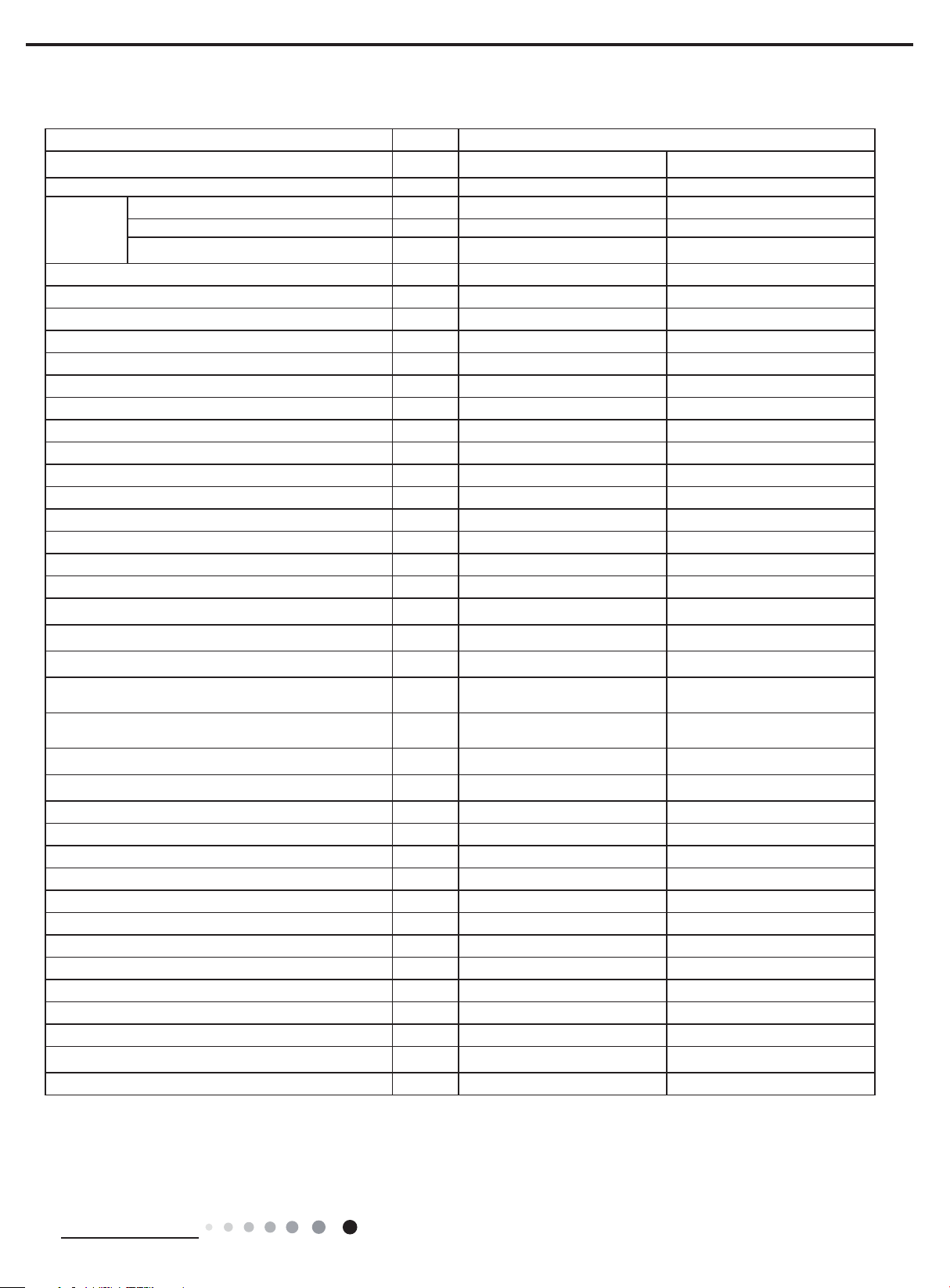
2. Specications
Parameter Unit Value
Model GPC10AN-K5NNA1A GPC12AN-K5NNA1A
Product Code CK010032300 CK010032400
Power
Supply
Rated Voltage V
Rated Frequency Hz 50 50
Phases 1 1
~
Cooling Capacity W 2900 3500
Heating Capacity W / /
Cooling Power Input W 935 1345
Heating Power Input W / /
Cooling Power Current A 4.1 5.9
Heating Power Current A / /
Rated Input W 1100 1550
Rated Current A 5.2 8.0
Air Flow Volume(H/M/L) m
3
/h 380/330/280 380/330/280
Dehumidifying Volume L/h 1.5 1.8
EER W/W 3.1 2.6
COP W/W / /
SEER / /
HSPF / /
Application Area m
2
Climate Type T1 T1
Isolation I I
Moisture Protection IPX0 IPX0
Permissible Excessive Operating Pressure for the
Discharge Side
Permissible Excessive Operating Pressure for the
Suction Side
MPa 3 3
MPa 1.5 1.5
Throttling Method Capillary Capillary
Defrosting Method / /
Fuse current A 3.15 3.15
o
Operation Temp
Ambient Temp (Cooling)
Ambient Temp (Heating)
C 16~30 16~30
o
C 16~35 16~35
o
C / /
Sound Pressure Level (H/M/L) dB (A) 53/51/49 53/51/49
Sound Power Level (H/M/L) dB (A) 64/62/60 64/62/60
Dimension (WXHXD) mm 405X835X385 405X835X385
Dimension of Carton Box (LXWXH) mm 577X451X864 577X451X864
Dimension of Package (LXWXH) mm 580X454X879 580X454X879
Net Weight kg 35.5 35.5
Gross Weight kg 41 41
Refrigerant R290 R290
Refrigerant Charge kg 0.3 0.28
220-240 220-240
15-22 15-22
Technical Information
17
Service Manual
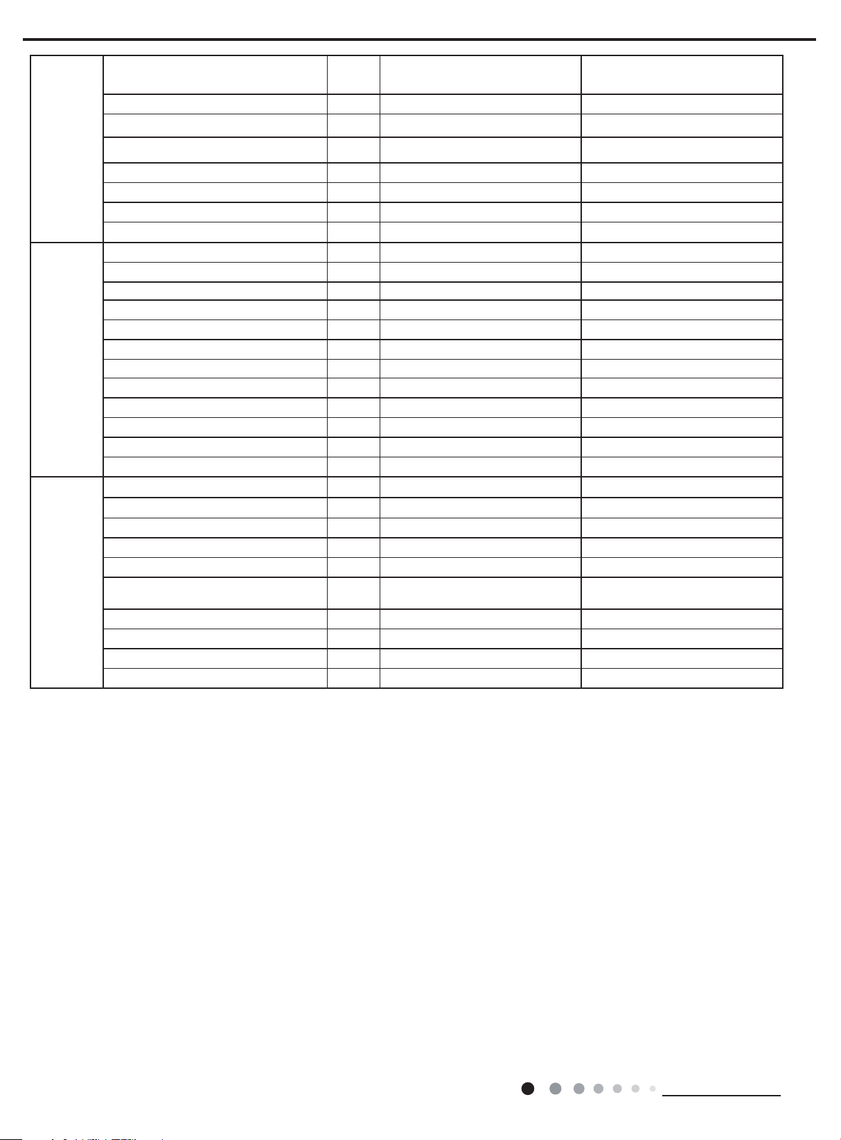
Compressor
Evaporator
Condenser
Compressor Manufacturer/Trademark
Compressor Model QXD-B172A030A QXD-B222A030
Compressor Oil 5GSD-TB or equivalent 5GSD-TB or equivalent
Compressor Type Rotary Rotary
L.R.A. A 21.5 26
Compressor RLA A 3.4 4.5
Compressor Power Input W 770 1000
Overload Protector HPA-022 HPA-030
Fan Type Centrifugal Centrifugal
Diameter Length(DXL) mm Φ204.6X72 Φ204.6X72
Cooling Speed(H/M/L) rpm 1000/860/730 1000/860/730
Heating Speed(H/M/L) W 1000/860/730 1000/860/730
Fan Motor RLA A 0.29 0.29
Fan Motor Capacitor μF 2.5 2.5
Form Aluminum Fin-copper Tube Aluminum Fin-copper Tube
Pipe Diameter mm Φ7 Φ7
Row-n Gap mm 2-1.4 2-1.4
Coil Length (LXDXW) mm 591X25.4X228.6 591X25.4X228.6
Swing Motor Model / /
Output of Swing Motor W / /
Fan Type Centrifugal Centrifugal
Fan Diameter mm Φ224.5X80 Φ224.5X80
Form Aluminum Fin-copper Tube Aluminum Fin-copper Tube
Pipe Diameter mm Φ5 Φ5
Rows-n Gap mm 3-1.3 + 1-1.4 2-1.3 + 1-1.4
Coil Length (LXDXW) mm 592X34.2X304.8/475X11.4X266.7 576X22.8X304.8/ 475X11.4X266.7
ZHUHAI LANDA COMPRESSOR
CO., LTD
ZHUHAI LANDA COMPRESSOR
CO., LTD
Fan Motor Speed rpm 980/800 980/800
Output of Fan Motor W 50 50
Fan Motor RLA A 0.5 0.5
Fan Motor Capacitor μF 2.5 2.5
The above data is subject to change without notice. Please refer to the nameplate of the unit.
18
Technical Information

Service Manual
Parameter Unit Value
Model GPC12AN-K5NNA1A GPH12AN-K5NNA1A
Product Code CK010032401 CK010031300
Power
Supply
Rated Voltage V
~
Rated Frequency Hz 50 50
Phases 1 1
220-240 220-240
Cooling Capacity W 3500 3500
Heating Capacity W / 3500
Cooling Power Input W 1345 1345
Heating Power Input W / 1130
Cooling Power Current A 5.9 5.9
Heating Power Current A / 4.9
Rated Input W 1550 1650
Rated Current A 8.0 8.4
Air Flow Volume(H/M/L) m
3
/h 380/330/280 380/330/280
Dehumidifying Volume L/h 1.8 1.8
EER W/W 2.6 2.6
COP W/W / 3.1
SEER / /
HSPF / /
Application Area m
2
15-22 15-22
Climate Type T1 T1
Isolation I I
Moisture Protection IPX0 IPX0
Permissible Excessive Operating Pressure for the
Discharge Side
Permissible Excessive Operating Pressure for the
Suction Side
MPa 3 3
MPa 1.5 1.5
Throttling Method Capillary Capillary
Defrosting Method / /
Fuse current A 3.15 3.15
o
Operation Temp
Ambient Temp (Cooling)
Ambient Temp (Heating)
C 16~30 16~30
o
C 16~35 16~35
o
C / 10~27
Sound Pressure Level (H/M/L) dB (A) 53/51/49 53/51/49
Sound Power Level (H/M/L) dB (A) 64/62/60 65/63/61
Dimension (WXHXD) mm 405X835X385 405X835X385
Dimension of Carton Box (LXWXH) mm 577X451X864 577X451X864
Dimension of Package (LXWXH) mm 580X454X879 580X454X879
Net Weight kg 35.5 36.0
Gross Weight kg 41 41.5
Refrigerant R290 R290
Refrigerant Charge kg 0.28 0.3
Technical Information
19

Service Manual
Compressor
Evaporator
Condenser
Compressor Manufacturer/Trademark
Compressor Model QXD-B222A030 QXD-B222A030
Compressor Oil 5GSD-TB or equivalent 5GSD-TB or equivalent
Compressor Type Rotary Rotary
L.R.A. A 26 26
Compressor RLA A 4.5 4.5
Compressor Power Input W 1000 1000
Overload Protector HPA-030 HPA-030
Fan Type Centrifugal Centrifugal
Diameter Length(DXL) mm Φ204.6X72 Φ204.6X72
Cooling Speed(H/M/L) rpm 1000/860/730 1000/860/730
Heating Speed(H/M/L) W / 1000/860/730
Fan Motor RLA A 0.29 0.29
Fan Motor Capacitor μF 2.5 2.5
Form Aluminum Fin-copper Tube Aluminum Fin-copper Tube
Pipe Diameter mm Φ7 Φ7
Row-n Gap mm 2-1.4 3-1.4
Coil Length (LXDXW) mm 591X25.4X228.6 520X38.1X228.6
Swing Motor Model / /
Output of Swing Motor W / /
Fan Type Centrifugal Centrifugal
Fan Diameter mm Φ224.5X80 Φ224.5X80
Form Aluminum Fin-copper Tube Aluminum Fin-copper Tube
Pipe Diameter mm Φ5 Φ5
Rows-n Gap mm 2-1.3 + 1-1.4 2-1.3 + 1-1.4
Coil Length (LXDXW) mm 576X22.8X304.8+475X11.4X266.7 576X22.8X304.8+475X11.4X266.7
ZHUHAI LANDA COMPRESSOR
CO., LTD
ZHUHAI LANDA COMPRESSOR
CO., LTD
Fan Motor Speed rpm 980/800 980/800
Output of Fan Motor W 50 50
Fan Motor RLA A 0.5 0.5
Fan Motor Capacitor μF 2.5 2.5
The above data is subject to change without notice. Please refer to the nameplate of the unit.
20
Technical Information
Service Manual
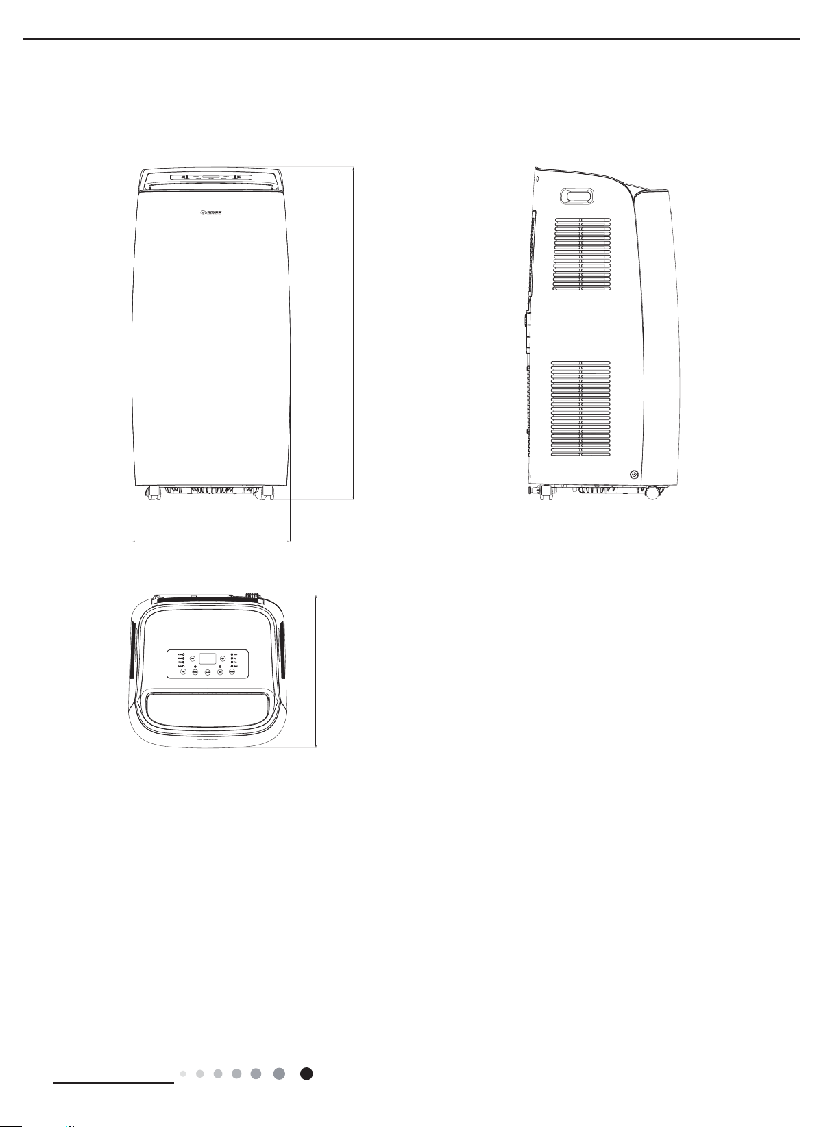
3. Outline Dimension Diagram
835
405
385
Unit:mm
Technical Information
21
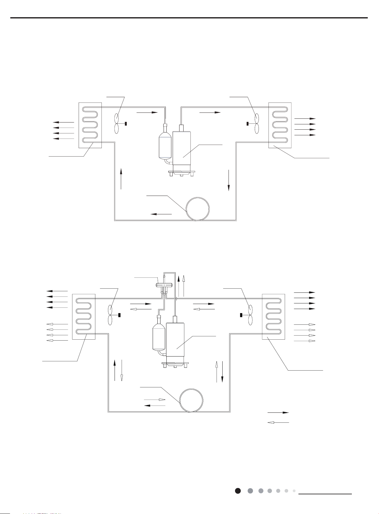
4. Refrigerant System Diagram
Cooling Only Model
Cooling & Heating Model
AIR
Service Manual
COOLED AIR
INDOOR COILS
COOLED AIR
CENTRIFUGAL FAN
CENTRIFUGAL FAN
CAPILLARY
REFRIGERANT FLOW DIRECTION
4-Way valve
COMPRESSOR
CENTRIFUGAL FAN
CENTRIFUGAL FAN
HOT DISCHARGED
OUTDOOR COILS
HOT DISCHARGED AIR
HOT AIR
INDOOR COILS
CAPILLARY
REFRIGERANT FLOW DIRECTION
COMPRESSOR
NOTES:
COOLED AIR
OUTDOOR COILS
COOLING MODE
HEATING MODE
22
Technical Information
Service Manual
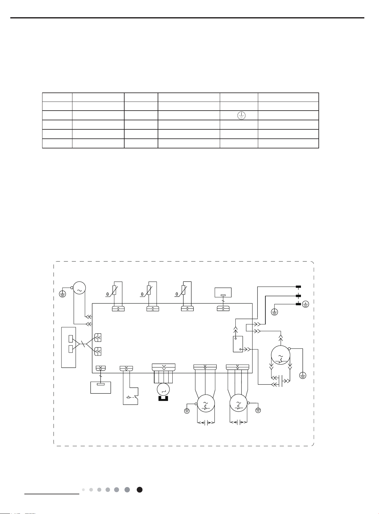
5. Electrical Part
5.1 Wiring Diagram
●Instruction
Symbol Symbol Color Symbol Symbol Color Symbol Name
WH White GN Green COMP Compressor
YE Yellow BN Brown Grounding wire
RD Red BU Blue / /
YEGN Yellow/Green BK Black / /
VT Violet OG Orange / /
●Electric Diagram
GPC10AN-K5NNA1A
GPC12AN-K5NNA1A(CK010032400/CK010032401)
:$7(502725
<(*1
0
5'
3(
',63
%8
1
:$7(5
',63
52207(03
6(1625
5220
78%(7(03
6(1625
5757
78%(
$3
0$,1%2$5'
',63
$3
',63/$<
%2$5'
:,),
$3
:,),
02'8/(
',63
+,*+:3
%.
5'
:$7(5/(9(/
6:,7&+
6$
6:,1*
0
67(33,1*
02725
28778%(7(03
6(1625
57
28778%(
2)$1
<(*1
3(
5'
0
&$3
5(&(,9(5
%2$5'
$3
5(&
$&/
.
5'
%1
&203
)$1
0
&$3
1
<(*1
%1
%8
&203
50
5'
5'
3(
%1%.
%8:+
<(*1*1
3(
&
&203
&$3
&
32:(5
/
1
<(*1
6
<(
3(
600007061240
Technical Information
&
'2:1)$1
02725
&
83)$1
02725
23
 Loading...