

Gree GMV-Y120WL/A-T, GMV-Y140WL/A-T, GMV-Y160WL/A-T Owner's Manual
Owner's Manual
Original Instructions
Commercial Air Conditioners
Photovoltaic Multi VRF
Models:
GMV-Y120WL/A-T
GMV-Y140WL/A-T
GMV-Y160WL/A-T

To Users
Thank you for selecting Gree’s product. Please read this instruction manual carefully
before installing and using the product, so as to master and correctly use the product. In order
to guide you to correctly install and use our product and achieve expected operating effect, we
hereby instruct as below:
(1) This appliance can be used by children aged from 8 years and above and persons with
reduced physical sensory or mental capabilities or lack of experience and knowledge if
they have been given supervision or instruction concerning use of the appliance in a
safe way and understand the hazards involved. Children shall not play with the
appliance. Cleaning and user maintenance shall not be made by children without
supervision.
(2) In order to ensure reliability of product, the product may consume some power under
stand-by status for maintaining normal communication of system and preheating
refrigerant and lubricant. If the product is not to be used for long, cut off the power
supply; please energize and preheat the unit in advance before reusing it.
(3) Please properly select the model according to actual using environment, otherwise it
may impact the using convenience.
(4) This product has gone through strict inspection and operational test before leaving the
factory. In order to avoid damage due to improper disassembly and inspection, which
may impact the normal operation of unit, please do not disassemble the unit by yourself.
You can contact with the special maintenance center of our company if necessary.
(5) For personal injury or property loss and damage caused by improper operation such as
improper installation and debugging, unnecessary maintenance, violation of related
national laws and rules and industrial standard, and violation of this instruction manual,
etc., we will bear no liability.
(6) When the product is faulted and cannot be operated, please contact with our
maintenance center as soon as possible by providing the following information.
1) Contents of nameplate of product (model, cooling/heating capacity, product No.,
ex-factory date).
2) Malfunction status (specify the situations before and after the error occurs).
(7) All the illustrations and information in the instruction manual are only for reference. In
order to make the product better, we will continuously conduct improvement and
innovation. We have the right to make necessary revision to the product from time to
time due to the reason of sales or production, and reserve the right to revise the
contents without further notice.
(8) The final right to interpret for this instruction manual belongs to Gree Electric Appliances
Inc. of Zhuhai.

Contents
1 SAFETY NOTICES (PLEASE BE SURE TO ABIDE) ......................................................................................... 1
2 PRODUCT INTRODUCTION ................................................................................................................................ 3
2.1 Names of Main Parts ............................................................................................................................................ 3
2.2 Combinations of Indoor and Outdoor Units ...................................................................................................... 4
2.3 Operating Range .................................................................................................................................................. 4
3 PREPARATION BEFORE INSTALLATION ......................................................................................................... 4
3.1 Standard Parts ....................................................................................................................................................... 4
3.2 Installation Site ...................................................................................................................................................... 5
3.3 Piping Work Requirements .................................................................................................................................. 5
4 INSTALLATION INSTRUCTION ........................................................................................................................... 6
4.1 Dimension of Outdoor Unit and Mounting Hole ................................................................................................ 6
4.2 Connection Pipe .................................................................................................................................................... 7
4.3 Installation of Connection Pipe ......................................................................................................................... 11
4.4 Vacuum Pumping, Refrigerant Adding ............................................................................................................. 14
4.5 Electric Wiring ..................................................................................................................................................... 16
4.6 Installation project of photovoltaic system ...................................................................................................... 19
5 CHECK ITEMS AFTER INSTALLATION AND TEST OPERATION ................................................................. 22
5.1 Check Items after Installation ............................................................................................................................ 22
5.2 Test operation and debugging........................................................................................................................... 22
6 COMMON MALFUNCTIONS AND TROUBLESHOOTING .............................................................................. 29
7 ERROR INDICATION .......................................................................................................................................... 30
8 FUNCTION SETTING OF OUTDOOR UNIT ...................................................................................................... 34
8.1 ODU Quiet Function ........................................................................................................................................... 34
8.2 Cool & Heat Function ......................................................................................................................................... 35
8.3 Forced Defrosting ............................................................................................................................................... 36
8.4 Restore Factory Defaults ................................................................................................................................... 37
8.5 Static Pressure Function .................................................................................................................................... 37
9 MAINTENANCE AND CARE .............................................................................................................................. 37
9.1 Outdoor Heat Exchanger ................................................................................................................................... 37
9.2 Drain Pipe ............................................................................................................................................................ 38
9.3 Notice before Seasonal Use ............................................................................................................................. 38
9.4 Maintenance after Seasonal Use ..................................................................................................................... 38
9.5 Parts Replacement ............................................................................................................................................. 38
10 AFTER-SALES SERVICE ................................................................................................................................. 38
Photovoltaic Multi VRF
1
1 Safety Notices (Please be sure to abide)
Warning: If not abide strictly, it may cause severe damage to the unit or the people.
Note: If not abide strictly, it may cause slight or medium damage to the unit or the
people.
This sign indicates that the operation must be prohibited. Improper operation may
cause severe damage or death to people.
This sign indicates that the items must be observed. Improper operation may cause
damage to people or property.
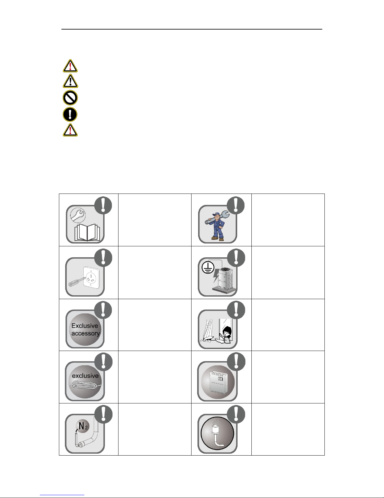
WARNING!
This product can’t be installed at corrosive, inflammable or explosive environment or the
place with special requirements, such as kitchen. Otherwise, it will affect the normal
operation or shorten the service life of the unit, or even cause fire hazard or serious injury.
As for above special places, please adopt special air conditioner with anti-corrosive or
anti-explosion function.
Please install the unit
according to instructions in
this manual. Read this
manual carefully before
starting up or checking the
machine.
Installation should be
performed by distributor or
qualified technicians. Do not
install the product by
yourself. Improper
installation may result in
water leakage, electric
shock or fire hazard.
Before installation, please
check the power cord if it
complies with the power
supply requirement on the
nameplate. Make sure the
power supply is safe.
This air conditioner must be
properly grounded through
the receptacle to avoid
electric shock. The ground
wire shouldn’t be connected
with gas pipe, water pipe,
lightning arrester or
telephone line.
When installing, specialized
parts and accessories must
be used. Otherwise, it may
result in water leakage,
electric shock or fire hazard.
R410A refrigerant can
produce poisonous gas
once it meets fire, so please
ventilate the room
immediately if refrigerant
leaks out during installation.
Diameter of power cord
must be large enough.
Damaged power cord or
connecting wire must be
replaced by specialized
electric cable.
After the power cord is
connected, please install the
cover of electric box to avoid
danger
Nitrogen must be charged
according to technical
requirements.
Short circuit is forbidden. Do
not cancel the pressure
switch, otherwise unit may
be damaged.
Photovoltaic Multi VRF
2
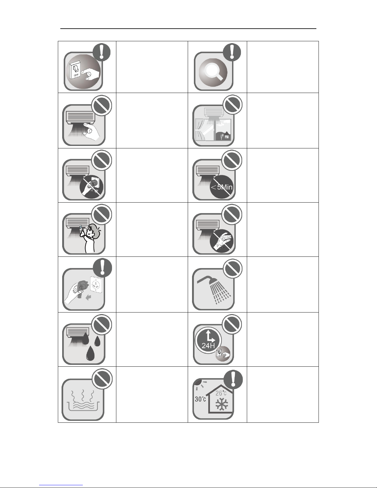
For units with wired
controllers, do not connect
power supply until the wired
controller is well installed.
Otherwise, the wired
controller cannot be used.
When installation is finished,
please check and make
sure the drain pipe, pipeline
and electric wire are all well
connected so as to avoid
water leakage, refrigerant
leakage, electric shock and
fire hazard.
Do not extend fingers or
objects into air outlet or
return air grille.
If you use gas heater or
petroleum heater in the
same room, please open the
door or window to maintain
good air circulation,
otherwise the room may be
lack of oxygen.
Never start or stop the air
conditioner by inserting or
removing the power cord.
Do not turn off the air
conditioner until it runs for at
least 5 minutes. Otherwise,
oil return of the compressor
will be affected.
Children are not allowed to
operate the air conditioner.
Do not operate the air
conditioner with wet hands.
Please turn off and unplug
your air conditioner before
cleaning. Otherwise, it may
cause electric shock or
personal injury.
Do not spray water on the
air conditioner or it will
cause malfunction or electric
shock.
Do not expose the air
conditioner directly under
damp or corrosive
surroundings.
Connect power 8 hours
before operation. Do not
disconnect power when you
want to stop the unit in a
short period of time, e.g. in
one night. (This is for
protecting the compressor.)
Volatile liquid like thinner or
gasoline will damage the
appearance of air
conditioner. (Please use soft
dry cloth and wet cloth with
mild detergent to clean
unit’s outer case.)
Under cool mode, do not set
the indoor temperature too
low. Keep the difference
between indoor temp and
outdoor temp within 5℃.
Photovoltaic Multi VRF
3
If abnormal condition occurs
(e.g. unpleasant smell),
please turn off the unit at
once and disconnect power
supply. Then contact Gree
authorized service center. If
the air conditioner continues
to operate despite of
abnormal condition, it may
be damaged and cause
electric shock or fire
hazard.)
Do not repair the air
conditioner by yourself.
Improper repair will cause
electric shock or fire hazard.
Please contact Gree
authorized service center
and ask professional
technicians to repair it.
This appliance can be used by children aged from 8 years and above and persons with
reduced physical, sensory or mental capabilities or lack of experience and knowledge if they
have been given supervision or instruction concerning use of the appliance in a safe way and
understand the hazards involved. Children shall not play with the appliance. Cleaning and user
maintenance shall not be made by children without supervision.
Install units according to national wiring codes.
If the supply cord is damaged, it musr be replaced by the manufacturer or its service agent
or a similarly qualified person in order to avoid a hazard.
An all-pole disconnection device which has at least 3mm clearances in all poles, and
disconnection must be incorporated in the fixed wiring in accordance with the wiring rules.
Gree Electric Appliances, Inc. of Zhuhai will not assume responsibility for any personal injury or property loss
caused by improper installation, improper debugging, unnecessary repair or not following the instructions of
this manual.
2 Product Introduction
Gree Multi VRF System adopts inverter compressor technology. By changing the
displacement of compressor, stepless capacity regulation within range of 10%~100% can be
realized. Various product lineups are provided with capacity range from 12.1kW to 16kW, which
can be widely used in residential, commercial and working area and especially applicable to
places with big load change. Gree residential air conditioner is absolutely your best choice.
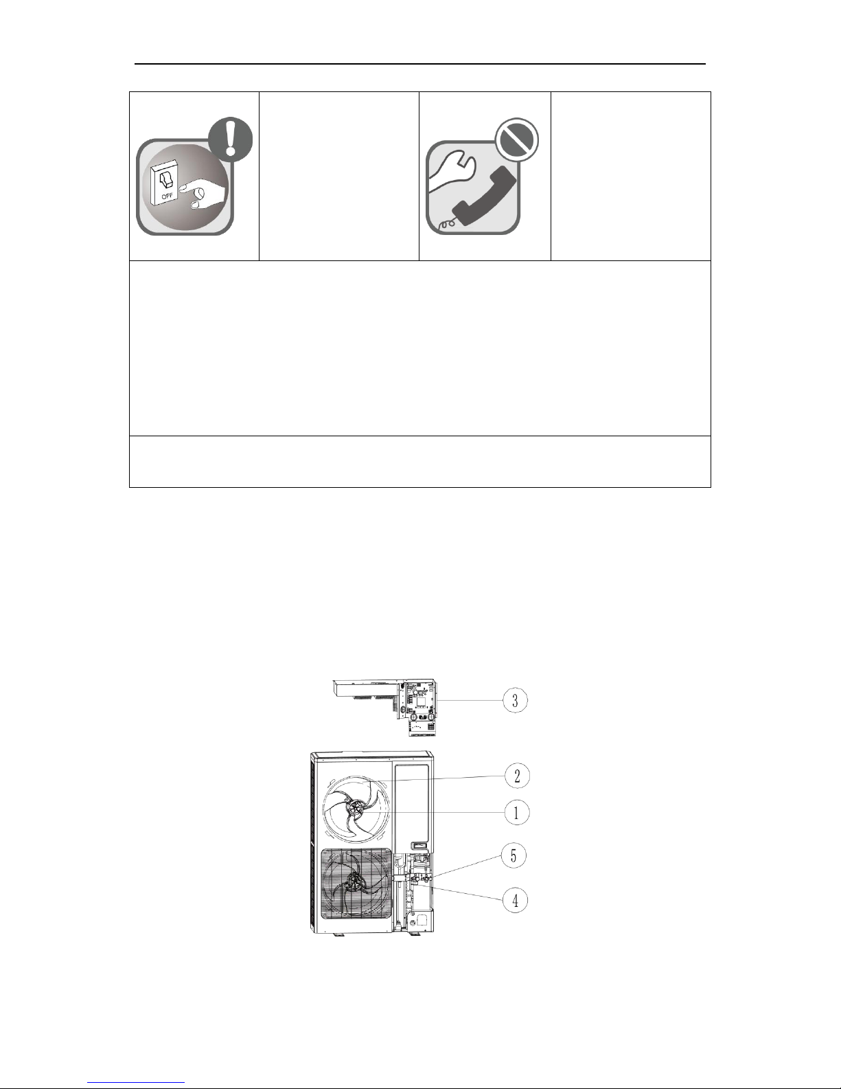
2.1 Names of Main Parts
GMV-Y120WL/A-T
GMV-Y140WL/A-T
GMV-Y160WL/A-T
Photovoltaic Multi VRF
4
No.
①
②
③
④
⑤
Name
Motor
Fan blade
Electric box
assembly
Gas pipe valve
Liquid pipe
valve
2.2 Combinations of Indoor and Outdoor Units
(1) See below the number of indoor units that can be connected to the outdoor unit.
(2) The total capacity of indoor units should be within 50%~135% of that of the outdoor
unit.
Model
Min sets of connectable IDUs
Max sets of connectable IDUs
GMV-Y120WL/A-T
2
7
GMV-Y140WL/A-T
2
8
GMV-Y160WL/A-T
2
9
(3) Can be connected to various indoor units. When any one of the indoor units receives
operating command, outdoor unit will start operation as per required capacity. When
all indoor units stop, outdoor unit will be shut off.
2.3 Operating Range
Cooling
Outdoor temperature: -5℃~52℃
Heating
Outdoor temperature: -20℃~27℃
3 Preparation before Installation
Note: Graphics here are only for reference. Please refer to actual products. Unspecified dimensions are
all in mm.
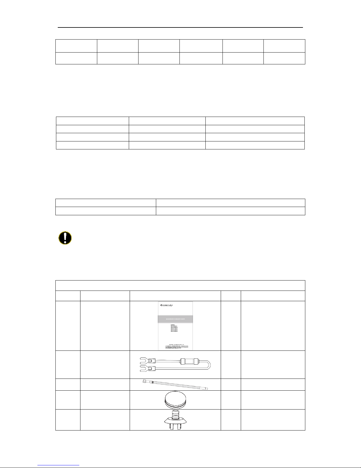
3.1 Standard Parts
Please use the supplied standard parts as required.
Parts for Outdoor Unit
No.
Name
Appearance
Qty
Remark
1
User Manual
1
2
Wiring (match with
resistance)
1
Must be connected to the
last IDU of communication
connection
3
Corrugated pipe
1
4
Chassis gluey plug
3
5
Drainage joint
1
Photovoltaic Multi VRF
5
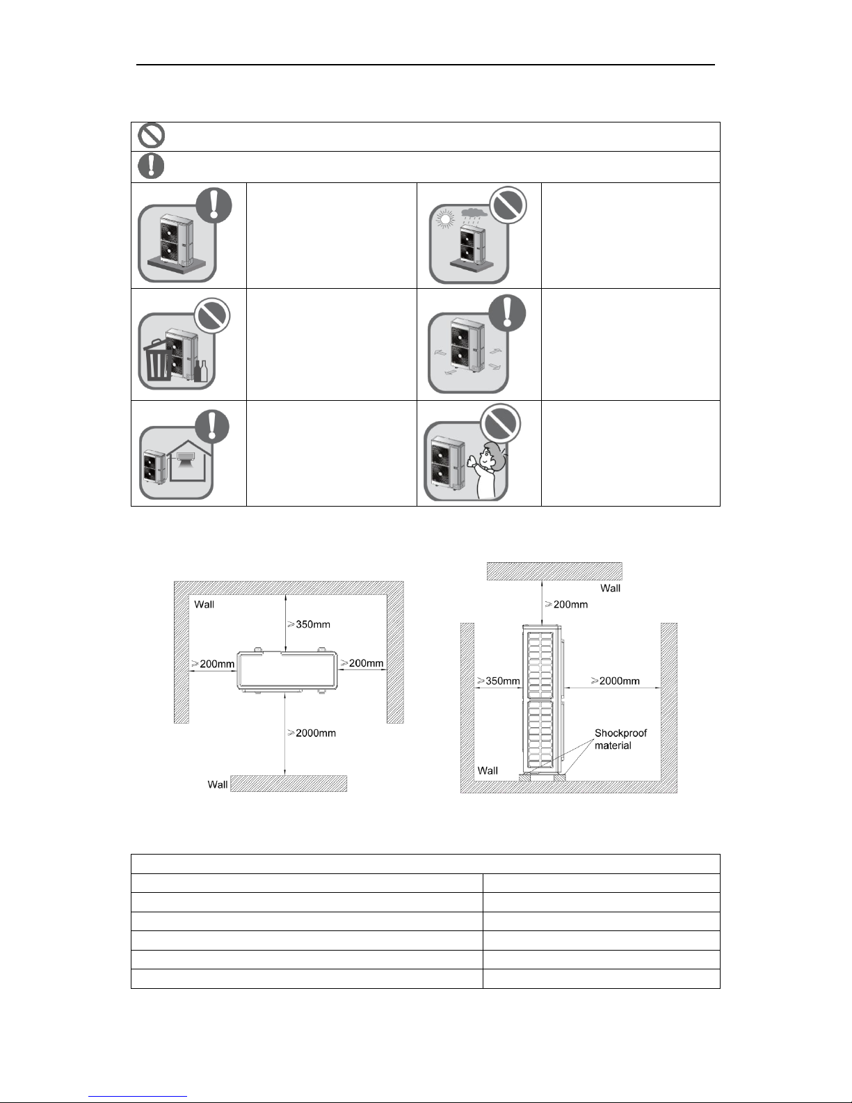
3.2 Installation Site
Forbidden item! Improper operation might lead to personal injury or even death.
Item needs to be followed. Improper operation might lead to personal injury or property damage.
Select a location which is
strong enough to hold unit’s
weight so that unit can stand
still and erect.
Make sure the unit is not
exposed to sun and rain. And
the location can resist dust,
typhoon and earthquake.
Please keep the unit away
from inflammable, explosive
and corrosive gas or waste
gas.
Make sure the location has
space for heat exchange and
maintenance so that unit can
operate reliably with good
ventilation.
ODU and IDU should stay as
close as possible to shorten
the length of refrigerant pipe
and reduce bend angles.
Select a location which is out of
children’s reach. Keep the unit
away from children.
If the ODU is totally surrounded by walls, please refer to the following figures for space
dimension:
3.3 Piping Work Requirements
Refer to the table below for piping work requirements:
R410A Refrigerant System
Outer diameter (mm/inch)
Wall thickness(mm)
Φ6.35(1/4)
≥0.8
Φ9.52(3/8)
≥0.8
Φ12.70(1/2)
≥0.8
Φ15.9(5/8)
≥1.0
Φ19.05(3/4)
≥1.0

Photovoltaic Multi VRF
6
4 Installation Instruction
Note: Graphics here are only for reference. Please refer to actual products. Unspecified dimensions are
all in mm.
4.1 Dimension of Outdoor Unit and Mounting Hole
Unit Outline and Installation Dimension(mm)
Unit: mm
Model
A B C D E
GMV-Y120WL/A-T
GMV-Y140WL/A-T
GMV-Y160WL/A-T
900
340
1345
572
378
Photovoltaic Multi VRF
7
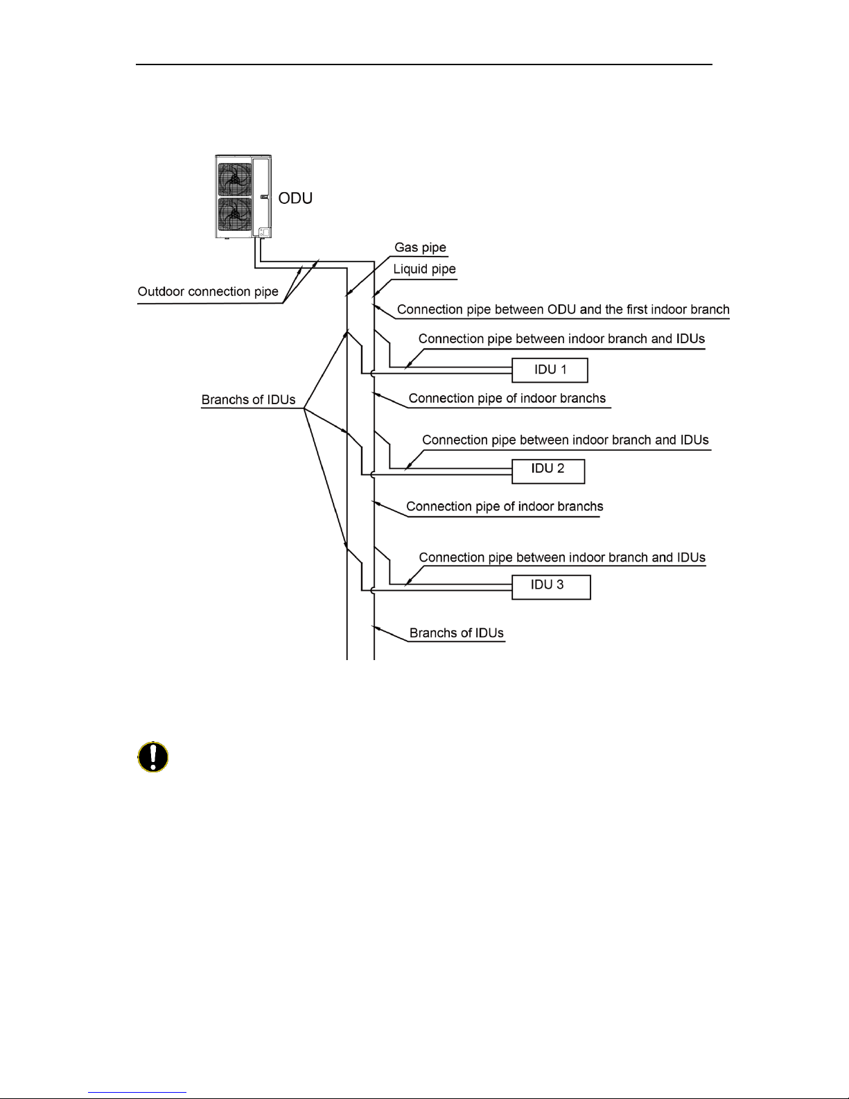
4.2 Connection Pipe
4.2.1 Schematic Diagram of Piping Connection
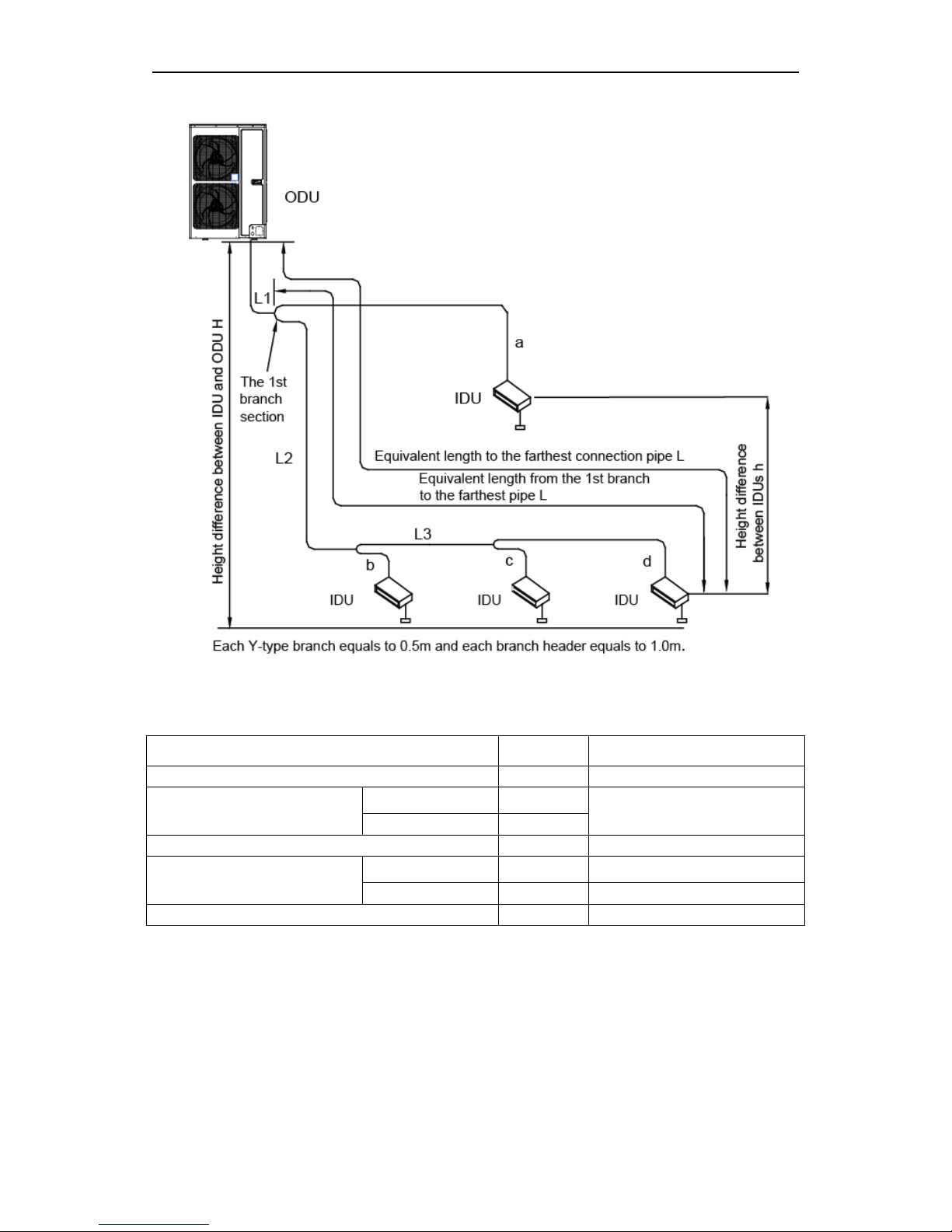
4.2.2 Allowable Length and Height Difference of Connection Pipe
Y type branch joint is adopted to connect indoor and outdoor units. Connecting method is
shown in the figure below:
Note:Equivalent length of one Y-type branch is 0.5m.
Photovoltaic Multi VRF
8
Allowable Length and Height Difference of Connection Pipe
Piping parameters of GMV-Y120WL/A-T, GMV-Y140WL/A-T, GMV-Y160WL/A-T,
Allowable
value
Fitting pipe
Total length (actual length) of fitting pipe
300m
L1+L2+L3+a+b+c+d
Length of farthest fitting pipe (m)
Actual length
120m
L1+L2+L3+d
Equivalent length
150m
From the 1st branch to the farthest indoor pipe
40m
L2+L3+d
Height difference between ODU
and IDU
ODU at upper side
50m
——
ODU at lower side
40m
——
Height difference between IDUs
15m
——
4.2.3 Dimension of Pipe (Main Pipe) from ODU to the 1st Indoor Branch
Dimension of pipe from ODU to the 1st indoor branch will be determined by the dimension
of outdoor connection pipe.
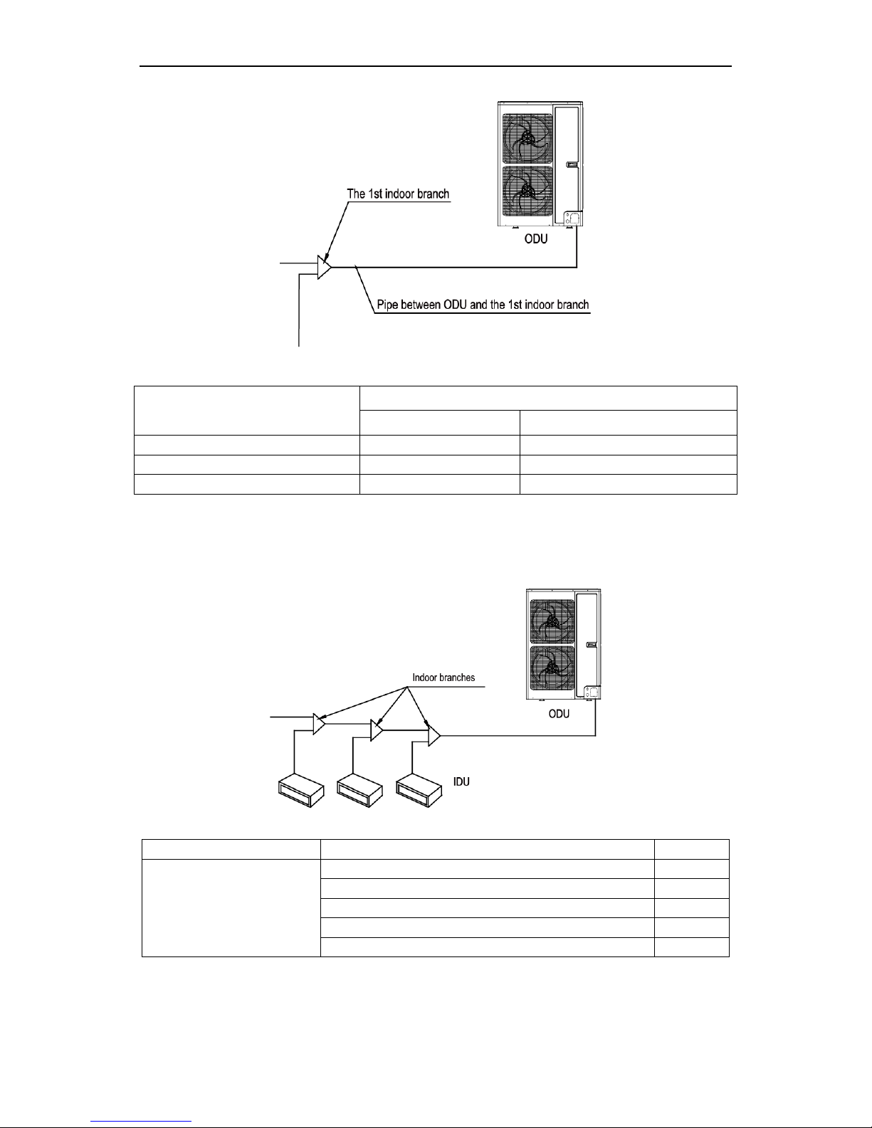
Photovoltaic Multi VRF
9
Dimension of outdoor connection pipe
Basic module
Pipe dimension
Gas pipe (mm)
Liquid pipe(mm)
GMV-Y120WL/A-T
Φ 15.9
Φ 9.52
GMV-Y140WL/A-T
Φ 15.9
Φ 9.52
GMV-Y160WL/A-T
Φ 19.05
Φ 9.52
4.2.4 Selection of Indoor Branches
Select indoor branches according to the total capacity of downstream indoor units. If the
capacity exceeds that of the outdoor unit, capacity of outdoor unit prevails.
R410A Refrigerant system
Total capacity of downstream indoor units X (kW)
Model
Y type branch
X<20
FQ01A
20≤X≤30
FQ01B
30<X≤70
FQ02
70<X≤135
FQ03
135<X
FQ04
4.2.5 Dimension of Pipe between Indoor Branches
Select pipe between indoor branches according to the capacity of downstream indoor units;
if the capacity exceeds that of the outdoor unit, capacity of outdoor unit prevails.
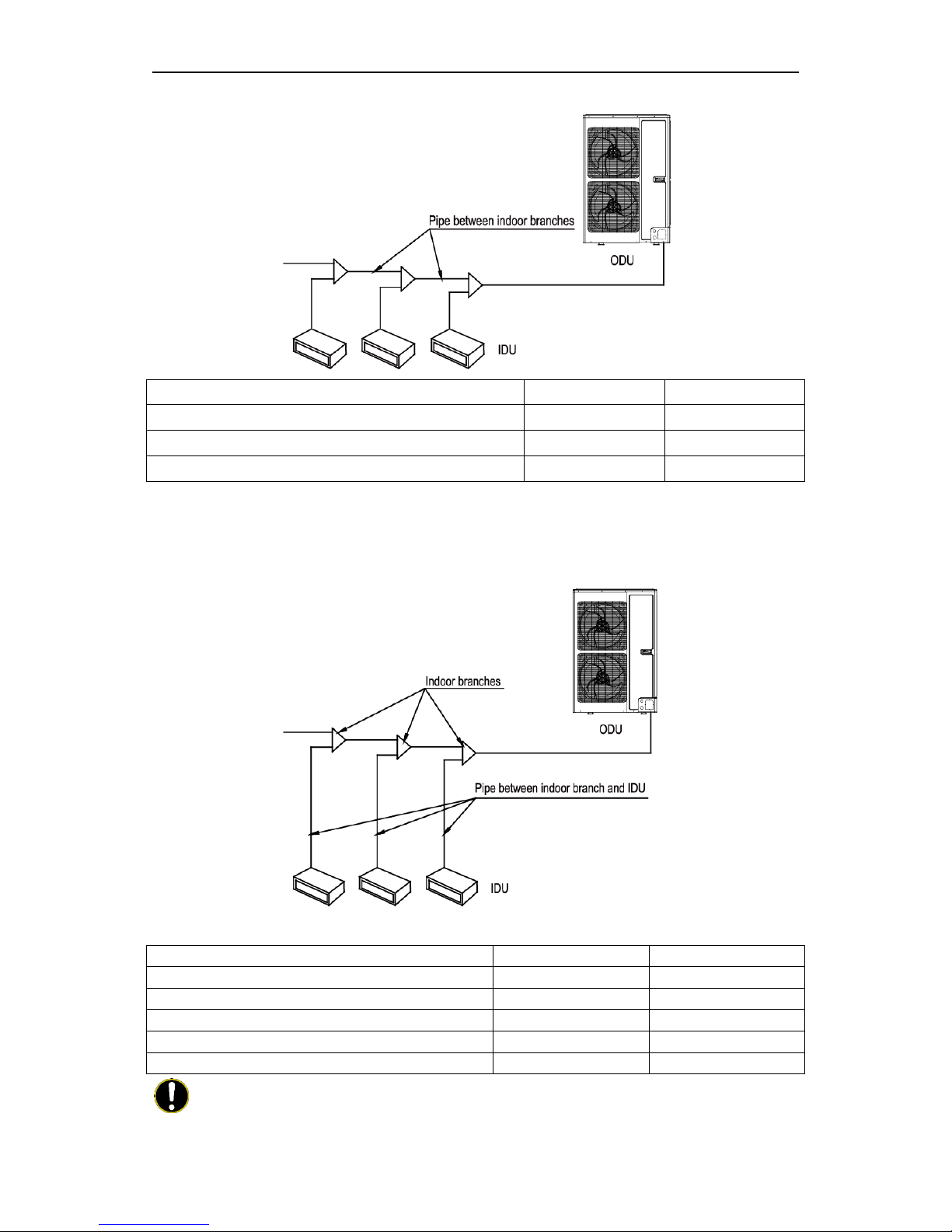
Photovoltaic Multi VRF
10
Total capacity of downstream indoor units C (kW)
Gas pipe(mm)
Liquid pipe(mm)
C ≤5.6
Φ12.7
Φ6.35
5.6<C≤14.2
Φ15.9
Φ9.52
14.2<C≤22.4
Φ19.05
Φ9.52
4.2.6 Dimension of Pipe between Indoor Branch and IDU
Dimension of pipe between indoor branch and IDU should be consistent with the
dimension of indoor pipe.
Rated capacity of IDU C(kW)
Gas pipe (mm)
Liquid pipe (mm)
C≤2.8
Φ9.52
Φ6.35
2.8<C≤5.0
Φ12.7
Φ6.35
5.0<C≤14.0
Φ15.9
Φ9.52
14.0<C≤16.0
Φ19.05
Φ9.52
16.0<C≤28.0
Φ22.2
Φ9.52
Note: If the distance between IDU and its nearest branch is over 10m, then the liquid pipe of IDU (rated
capacity ≤5.0kW) shall be enlarged.
 Loading...