

Gree GMV-Q504WM/B-X, GMV-Q280WM/B-X, GMV-Q615WM/B-X, GMV-Q560WM/B-X, GMV-Q400WM/B-X Owner's Manual
...
Heat Recovery DC Inverter Multi
VRF Unit
…
Owner's Manual
Air Conditioners
Models:
GMV-Q224WM/B-X
GMV-Q280WM/B-X
GMV-Q335WM/B-X
GMV-Q400WM/B-X
GMV-Q450WM/B-X
GMV-Q504WM/B-X
GMV-Q1800WM/B-X
Thank you for choosing Air Conditioners, please read this owner’s manual carefully before
operation and retain it for future reference.If you have lost the Owner’s Manual, please contact
the local agent or visit www.gree.com or send email to global@gree.com.cn or electronic
version.
GREE reserves the right to interpret this manual which will be subject to any change due to
product improvement without further notice.
GREE Electric Appliances, Inc. of Zhuhai reserves the final right to interpret this manual.

Preface
Gree DC Inverter Multi VRF System, with the most advanced technologies in the world,
uses eco-friendly refrigerant R410A as its cooling medium. For correct installation and
operation, please read this manual carefully. Before reading the manual, please note that:
(1) To ensure safety when operating the units, please strictly follow the instructions in this
manual.
(2) The total capacity of running indoor units must not exceed that of the outdoor units.
Otherwise, the cooling (heating) effect of each IDU would be poor.
(3) Make sure that this manual is kept by direct operators and maintainers.
(4) In case of malfunction, please examine the following items and contact our authorized
service centers as soon as possible.
1) Air conditioner’s nameplate (model, cooling capacity, product code, ex-factory date);
2) Malfunction status (detail description of conditions before and after malfunction occurs)
(5) All units have been strictly tested and proved to be qualified before ex-factory. To
avoid damage or operation failure which may be caused by improper disassembly, please do
not disassemble units by yourself. If disassembly is needed, please contact our authorized
service centers.
(6) All graphics and information in this manual are only for reference. Manufacturer
reserves the right for changes in terms of sales or production at any time and without prior
notice.
(7) Under the standby status, the unit will consume a little power for ensuring reliability of
the complete unit, maintaining normal communication and preheating refrigerant. When the
unit won’t be used for a long time, please cut off the power of the complete unit. However,
please preheat it when operating the unit next time.
This appliance can be used by children aged from 8 years and above and persons with
reduced physical, sensory or mental capabilities or lack of experience and knowledge if they
have been given supervision or instruction concerning use of the appliance in a safe way and
understand the hazards involved. Children shall not play with the appliance. Cleaning and
user maintenance shall not be made by children without supervision.
Correct Disposal of this product: This marking indicates that this product should not be
disposed with other household wastes throughout the EU. To prevent possible harm to the
environment or human health from uncontrolled waste disposal, recycle it responsibly to
promote the sustainable reuse of material resources. To return your used device, please use
the return and collection systems or contact the retailer where the product was purchased.
They can take this product for environmental safe recycling.

Contents
1 SAFETY PRECAUTIONS ................................................................................................................................... 1
2 PRODUCT INTRODUCTION ............................................................................................................................. 3
2.1 NAMES OF MAIN PARTS................................................................................................................................ 3
2.2 COMBINATIONS OF OUTDOOR UNITS ........................................................................................................... 3
2.3 COMBINATIONS OF INDOOR AND OUTDOOR UNITS ..................................................................................... 4
2.4 OPERATION RANGE ...................................................................................................................................... 6
3 PREPARATION BEFORE INSTALLATION ............................................................................................ 6
3.1 STANDARD PARTS ........................................................................................................................................ 6
3.2 INSTALLATION SITE....................................................................................................................................... 6
3.3 CONNECTION PIPE REQUIREMENT ............................................................................................................ 10
4 INSTALLATION INSTRUCTIONS .......................................................................................................... 11
4.1 DIMENSION OF OUTDOOR UNIT AND MOUNTING HOLE ............................................................................. 11
4.2 REFRIGERANT CONNECTION PIPE OF INDOOR AND OUTDOOR UNITS ...................................................... 12
4.3 INSTALLATION OF REFRIGERANT CONNECTION PIPE ................................................................................ 21
4.4 VACUUM PUMPING, REFRIGERANT ADDING .............................................................................................. 24
4.5 ELECTRIC WIRING ...................................................................................................................................... 26
4.6 SYSTEM COMMUNICATION FEATURES ....................................................................................................... 32
4.7 CONNECTION METHODS AND PROCEDURE OF COMMUNICATION SYSTEM .............................................. 38
4.8 DIAGRAM OF EXTERNAL ELECTRIC WIRING .............................................................................................. 45
5 CHECK ITEMS AFTER INSTALLATION AND TEST OPERATION .................................................... 47
5.1 CHECK ITEMS AFTER INSTALLATION ........................................................................................................... 47
5.2 TRIAL OPERATION ...................................................................................................................................... 47
6 COMMON MALFUNCTION AND TROUBLESHOOTING .................................................................... 59
7 ERROR INDICATION ............................................................................................................................... 60
8 MAINTENANCE AND CARE .................................................................................................................. 64
8.1 OUTDOOR HEAT EXCHANGER.................................................................................................................... 64
8.2 DRAIN PIPE ................................................................................................................................................. 64
8.3 NOTICE BEFORE SEASONAL USE ............................................................................................................... 64
8.4 MAINTENANCE AFTER SEASONAL USE ...................................................................................................... 64
8.5 PARTS REPLACEMENT ............................................................................................................................... 64
9 AFTER-SALES SERVICE ....................................................................................................................... 64
Heat Recovery DC Inverter Multi VRF Unit
Please install the unit
according to instructions
in this manual. Read this
manual carefully before
starting up or checking the
machine.
Installation should be
performed by distributor or
qualified personnel. Do
not install the product by
yourself. Improper
installation will result in
water leakage, electric
shock or fire hazard.
Before installation, please
check the power cord if it
complies with the power
supply requirement on the
nameplate. Make sure the
power supply is safe.
This air conditioner must
be properly grounded
through the receptacle to
avoid electric shock. The
ground wire shouldn’t be
connected with gas pipe,
water pipe, lightning
arrester or telephone line.
When installing,
specialized parts and
accessories must be
used. Otherwise, it may
result in water leakage,
electric shock or fire
hazard.
R410A refrigerant can
produce poisonous gas
once it meets fire, so
please ventilate the room
immediately if refrigerant
leaks out during
installation.
Diameter of power cord
must be large enough.
Damaged power cord or
connecting wire must be
replaced by specialized
electric cable.
After the power cord is
connected, please install
the cover of electric box to
avoid danger.
Nitrogen must be charged
according to technical
requirements.
Short circuit is forbidden.
Do not cancel the
pressure switch,
otherwise unit may be
damaged.
For units with wired
controllers, do not connect
power supply until the
wired controller is well
installed. Otherwise, the
wired controller cannot be
used.
When installation is
finished, please check
and make sure the drain
pipe, pipeline and electric
wire are all well connected
to avoid water leakage,
refrigerant leakage,
electric shock and fire
hazard.
Do not extend fingers or
objects into air outlet or
the return air grille.
If gas heater or petroleum
heater is used in the same
room, please open the
door or window to
maintain good air
circulation, otherwise an
oxygen shortage may
occur,
1 Safety Precautions
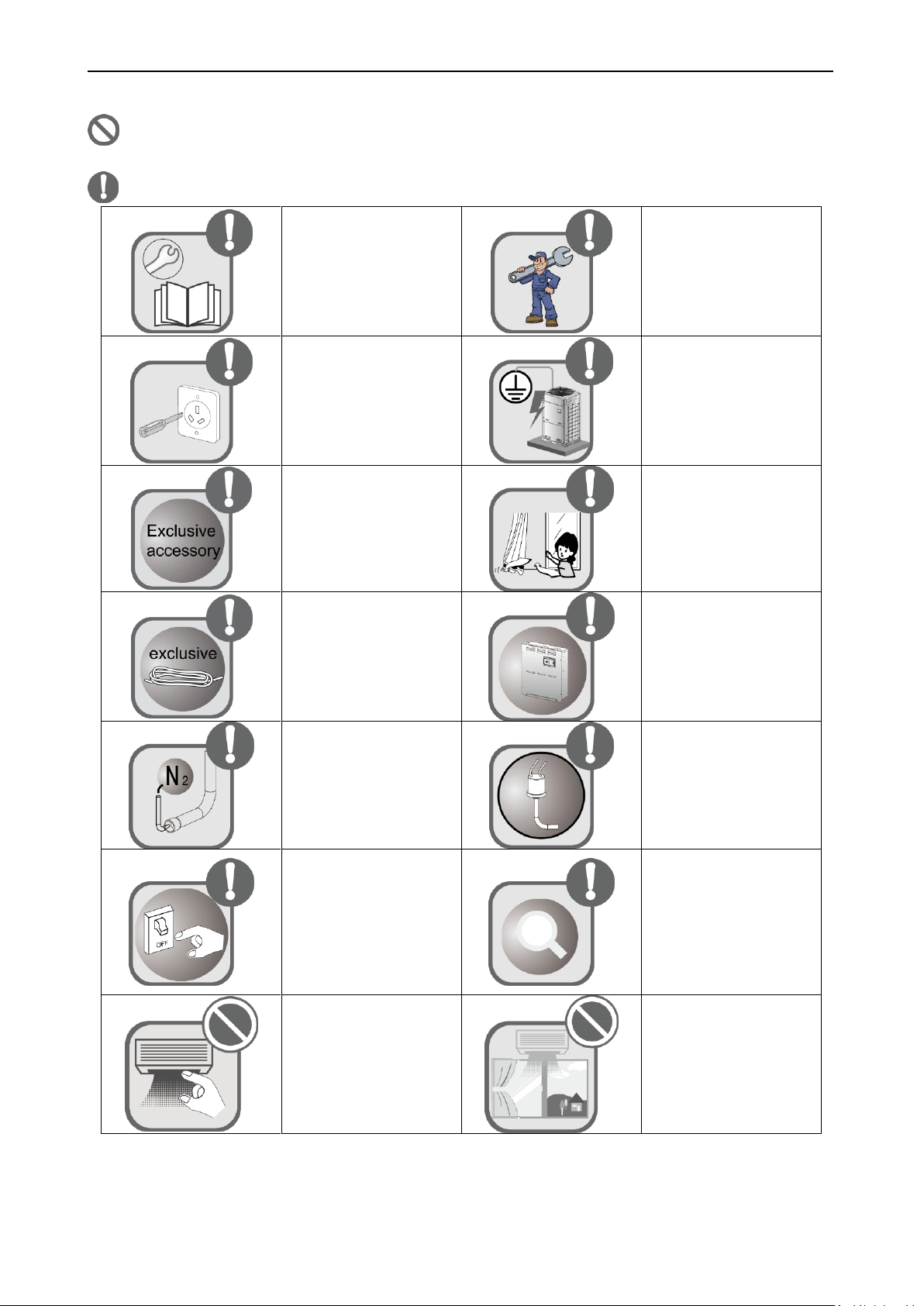
means items that must be forbidden! Otherwise, it may lead to personal injury or death or
serious damage.
means items that must be followed! Otherwise, it may lead to personal injury or property loss.
1

Heat Recovery DC Inverter Multi VRF Unit
Do not operate or stop the
unit by inserting or pulling
out the power plug.
Do not turn off the unit
until it runs for at least 5
minutes. Otherwise, oil
return of the compressor
will be affected.
Children are not allowed
to operate the air
conditioner.
Do not operate the air
conditioner with wet
hands.
Please turn off and unplug
your air conditioner before
cleaning. Otherwise,
electric shock or personal
injury may occur.
Do not spray water on the
air conditioner or clean it
with water, otherwise
malfunction or electric
shock may occur.
Do not expose the air
conditioner directly under
damp or corrosive
surroundings.
Connect power 8 hours
before operation. Do not
disconnect power when
you want to stop the unit
in a short period of time,
e.g. in one night. (This is
for protecting the
compressor.)
Volatile liquid like thinner
or gasoline will damage
the appearance of air
conditioner. (Please use
soft dry cloth and wet
cloth with mild detergent
to clean unit’s outer case.)
Under cool mode, do not
set the indoor temperature
too low. Keep the
difference between indoor
temp and outdoor temp
within 5℃.
If abnormal condition
occurs (e.g. unpleasant
smell), please turn off the
unit at once and
disconnect power supply.
Then contact Gree
authorized service center.
If the air conditioner
continues to operate
despite of abnormal
condition, it may be
damaged and cause
electric shock or fire
hazard.)
Do not repair the air
conditioner by yourself.
Improper repair will cause
electric shock or fire
hazard. Please contact
Gree authorized service
center and ask
professional personnel to
repair it.
Gree Electric Appliances, Inc. of Zhuhai will not assume responsibility for any personal injury or property
loss caused by improper installation, improper test running, and unnecessary repair or not following the
instructions of this manual.
2
Heat Recovery DC Inverter Multi VRF Unit
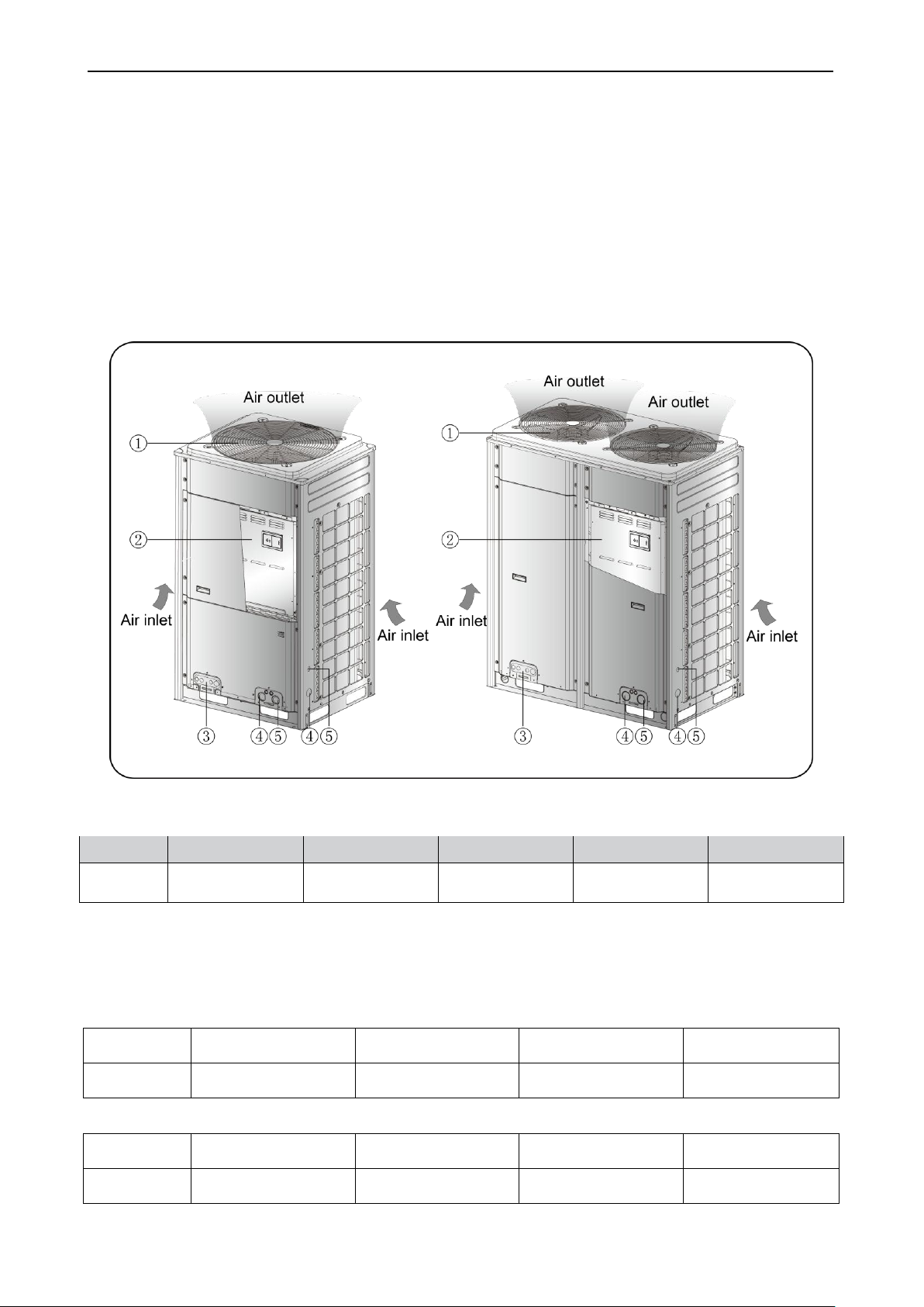
No,
① ② ③ ④ ⑤
Name
Fan motor, motor
Electric box
assembly
Valve interface
Power cord
through-hole
Communication wire
through-hole
Model
(Combined)
GMV-Q504WM/B-X
GMV-Q560WM/B-X
GMV-Q615WM/B-X
GMV-Q680WM/B-X
Model (Single)
GMV-Q224WM/B-X
+ GMV-Q280WM/B-X
GMV-Q280WM/B-X
+ GMV-Q280WM/B-X
GMV-Q280WM/B-X
+ GMV-Q335WM/B-X
GMV-Q280WM/B-X
+ GMV-Q400WM/B-X
Model
(Combined)
GMV-Q730WM/B-X
GMV-Q785WM/B-X
GMV-Q850WM/B-X
GMV-Q900WM/B-X
Model (Single)
GMV-Q280WM/B-X
+ GMV-Q450WM/B-X
GMV-Q335WM/B-X
+ GMV-Q450WM/B-X
GMV-Q400WM/B-X
+ GMV-Q450WM/B-X
GMV-Q450WM/B-X
+ GMV-Q450WM/B-X
2 Product Introduction
Gree Modular Heat Recovery Multi VRF System adopts inverter compressor technology. By
changing the displacement of compressor, stepless capacity regulation can be realized. Various
product lineups are provided with capacity range from 22.4kW to 180kW, and indoor units within a
same system can operate in cooling or heating mode in the meantime. This system can be widely
used in commercial and working area and is especially applicable to places with big load change.
Gree commercial multi VRF system is absolutely your best choice.
2.1 Names of Main Parts
Figure 1
2.2 Combinations of Outdoor Units
2.2.2 GMV5 HR DC Inverter Heat Recovery Multi VRF Units
3
Heat Recovery DC Inverter Multi VRF Unit
Model
(Combined)
GMV-Q960WM/B-X
GMV-Q1010WM/B-X
GMV-Q1065WM/B-X
GMV-Q1130WM/B-X
Model (Single)
GMV-Q280WM/B-X
+ GMV-Q280WM/B-X
+ GMV-Q400WM/B-X
GMV-Q280WM/B-X
+ GMV-Q280WM/B-X
+ GMV-Q450WM/B-X
GMV-Q280WM/B-X
+ GMV-Q335WM/B-X
+ GMV-Q450WM/B-X
GMV-Q280WM/B-X
+ GMV-Q400WM/B-X
+ GMV-Q450WM/B-X
Model
(Combined)
GMV-Q1180WM/B-X
GMV-Q1235WM/B-X
GMV-Q1300WM/B-X
GMV-Q1350WM/B-X
Model (Single)
GMV-Q280WM/B-X
+ GMV-Q450WM/B-X
+ GMV-Q450WM/B-X
GMV-Q335WM/B-X
+ GMV-Q450WM/B-X
+ GMV-Q450WM/B-X
GMV-Q400WM/B-X
+ GMV-Q450WM/B-X
+ GMV-Q450WM/B-X
GMV-Q450WM/B-X
+ GMV-Q450WM/B-X
+ GMV-Q450WM/B-X
Model
(Combined)
GMV-Q1410WM/B-X
GMV-Q1460WM/B-X
GMV-Q1515WM/B-X
GMV-Q1580WM/B-X
Model (Single)
GMV-Q280WM/B-X
+ GMV-Q280WM/B-X
+ GMV-Q400WM/B-X
+ GMV-Q450WM/B-X
GMV-Q280WM/B-X
+ GMV-Q280WM/B-X
+ GMV-Q450WM/B-X
+ GMV-Q450WM/B-X
GMV-Q280WM/B-X
+ GMV-Q335WM/B-X
+ GMV-Q450WM/B-X
+ GMV-Q450WM/B-X
GMV-Q280WM/B-X
+ GMV-Q400WM/B-X
+ GMV-Q450WM/B-X
+ GMV-Q450WM/B-X
Model
(Combined)
GMV-Q1630WM/B-X
GMV-Q1685WM/B-X
GMV-Q1750WM/B-X
GMV-Q1800WM/B-X
Model (Single)
GMV-Q280WM/B-X
+ GMV-Q450WM/B-X
+ GMV-Q450WM/B-X
+ GMV-Q450WM/B-X
GMV-Q335WM/B-X
+ GMV-Q450WM/B-X
+ GMV-Q450WM/B-X
+ GMV-Q450WM/B-X
GMV-Q400WM/B-X
+ GMV-Q450WM/B-X
+ GMV-Q450WM/B-X
+ GMV-Q450WM/B-X
GMV-Q450WM/B-X
+ GMV-Q450WM/B-X
+ GMV-Q450WM/B-X
+ GMV-Q450WM/B-X
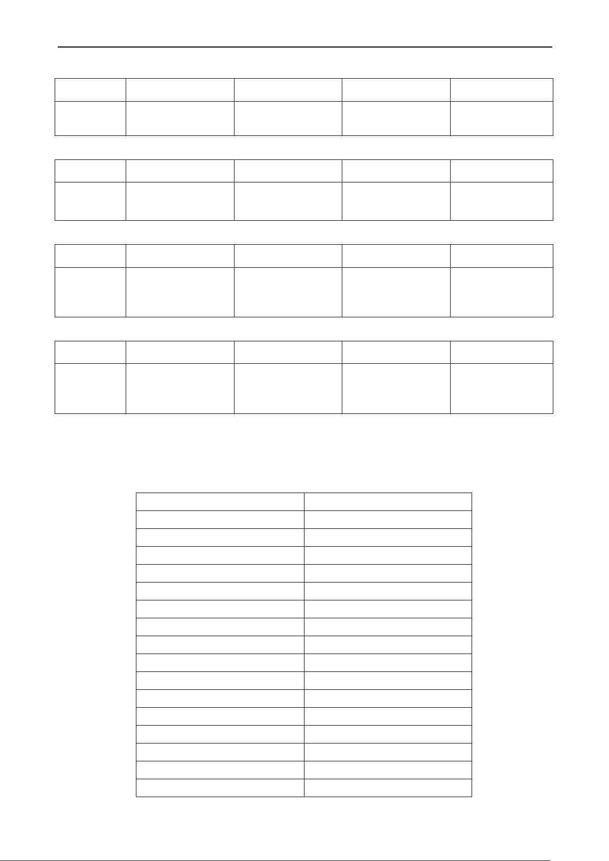
Model of ODU
Max number of connectable IDUs
GMV-Q224WM/B-X
13
GMV-Q280WM/B-X
16
GMV-Q335WM/B-X
19
GMV-Q400WM/B-X
23
GMV-Q450WM/B-X
26
GMV-Q504WM/B-X
29
GMV-Q560WM/B-X
33
GMV-Q615WM/B-X
36
GMV-Q680WM/B-X
39
GMV-Q730WM/B-X
43
GMV-Q785WM/B-X
46
GMV-Q850WM/B-X
50
GMV-Q900WM/B-X
53
GMV-Q960WM/B-X
56
GMV-Q1010WM/B-X
59
GMV-Q1065WM/B-X
63
2.3 Combinations of Indoor and Outdoor Units
(1) See below the number of indoor units that can be connected to an outdoor unit.
4
Heat Recovery DC Inverter Multi VRF Unit
GMV-Q1130WM/B-X
64
GMV-Q1180WM/B-X
64
GMV-Q1235WM/B-X
64
GMV-Q1300WM/B-X
64
GMV-Q1350WM/B-X
64
GMV-Q1410WM/B-X
66
GMV-Q1460WM/B-X
69
GMV-Q1515WM/B-X
71
GMV-Q1580WM/B-X
74
GMV-Q1630WM/B-X
77
GMV-Q1685WM/B-X
80
GMV-Q1750WM/B-X
80
GMV-Q1800WM/B-X
80
(2) The total capacity of indoor units should be within 50%~135% of that of the outdoor unit.
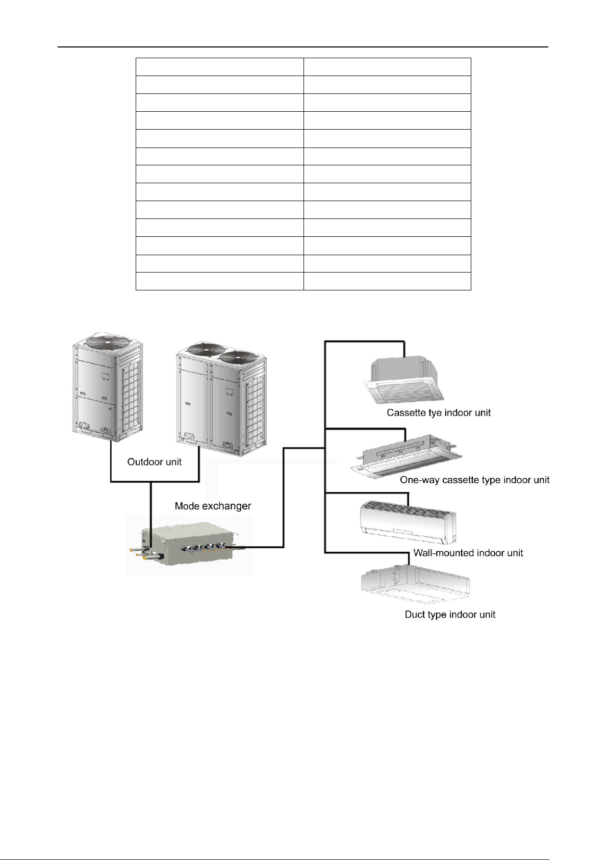
Figure 2
(3) Outdoor units of Modular DC Inverter Heat Recovery System can be connected to multi VRF
indoor units, including cassette type unit, one-way cassette type unit, wall-mounted unit and
duct type unit, as shown in figure 2. When any one of the indoor units receives operating
command, outdoor unit will start operation as per required capacity. When all indoor units stop,
outdoor unit will be shut off. Please note that outdoor unit can’t be connected to indoor unit
directly. Heat pump mode exchanger must be installed between outdoor unit and indoor unit.
5
Heat Recovery DC Inverter Multi VRF Unit
Cooling operation
Outdoor temperature -5℃~50℃
Heating operation
Outdoor temperature -20℃~24℃
Heat recovery operation
Outdoor temperature -10℃~20℃
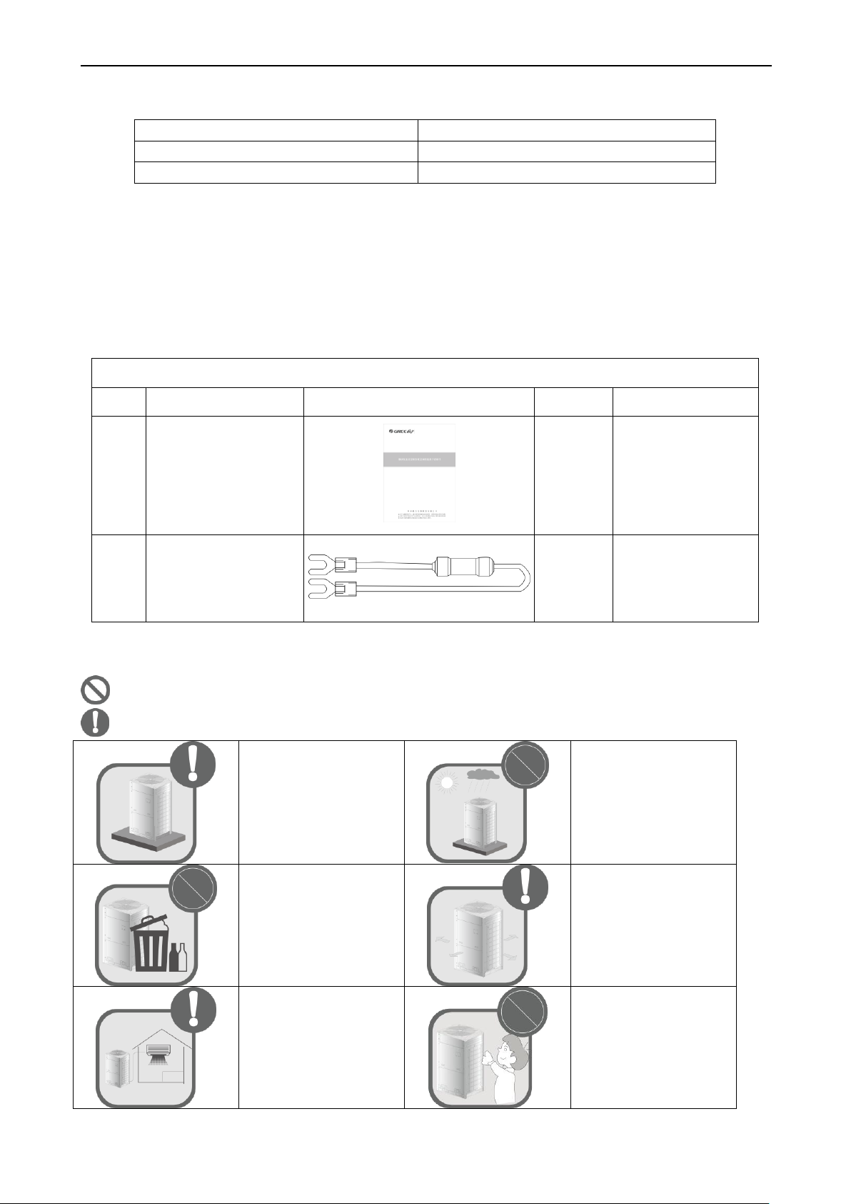
Parts of Outdoor Unit
No.
Name
Appearance
Qty
Remarks
1
User Manual
1( pc)
2
Wire (match with
resistance)
1( pc)
Must be connected to
the last heat pump
mode exchanger of
communication
connection
Select a location which is
strong enough to hold
unit’s weight so that unit
can stand still and erect.
Make sure the unit is not
exposed to sun and rain.
And the location can resist
dust, typhoon and
earthquake.
Please keep the unit away
from inflammable,
explosive and corrosive
gas or waste gas.
Make sure the location
has space for heat
exchange and
maintenance so that unit
can operate reliably with
good ventilation.
ODU and IDU should stay
together as close as
possible to shorten the
length of refrigerant pipe
and reduce bend angles.
Select a location which is
out of children’s reach.
Keep the unit away from
children.
2.4 Operation Range
3 Preparation before Installation
Note: Graphics here are only for reference. Please refer to actual products. Unspecified dimensions
are all in mm.
3.1 Standard Parts
Please use the supplied standard parts as required.
3.2 Installation Site
Never do this! This symbol indicates the possibility of death or serious injury.
Always do this! This symbol indicates the possibility of personal injury or property damage.
6
Heat Recovery DC Inverter Multi VRF Unit
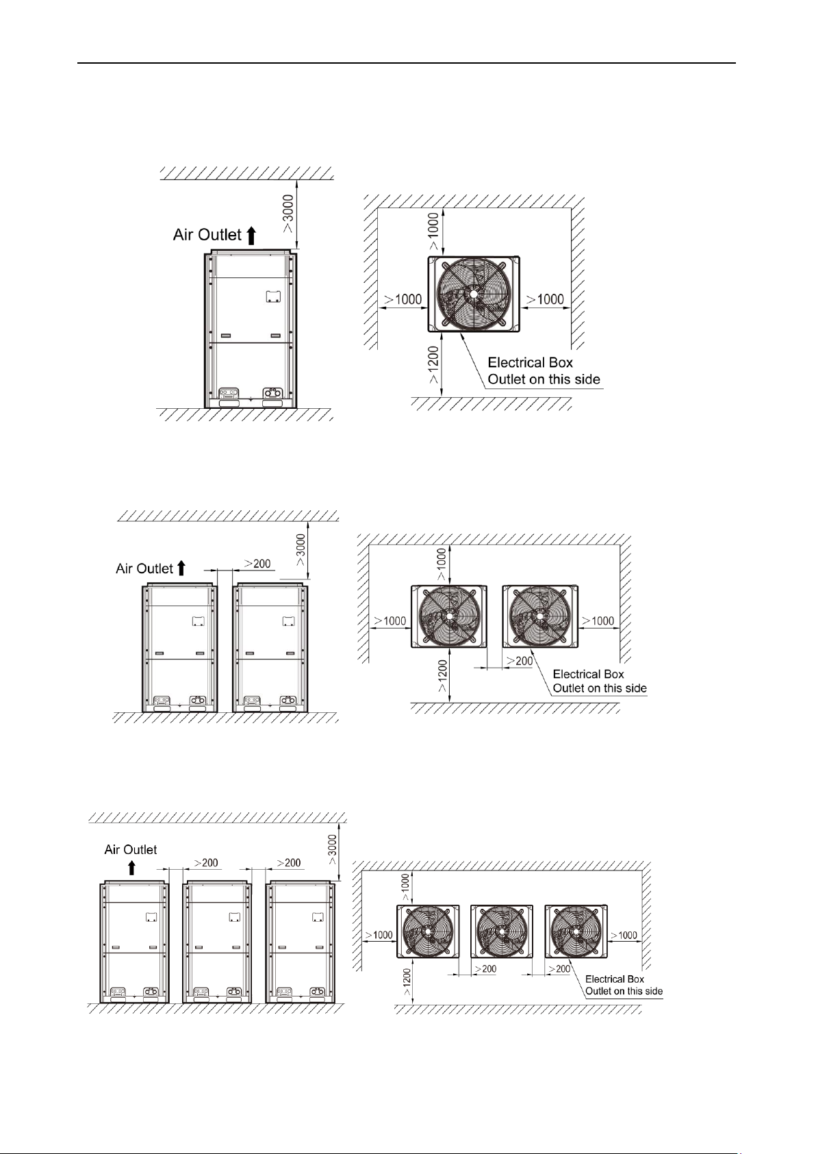
3.2.1 If the ODU is totally surrounded by walls, please refer to the following figures for
space dimension:
3.2.1.1 Installation space requirement for a single module
Unit: mm
Figure 3
3.2.1.2 Installation space requirement for twin modules
Figure 4
3.2.1.3 Installation space requirement for three modules
Unit: mm
Figure 5
7
Unit: mm
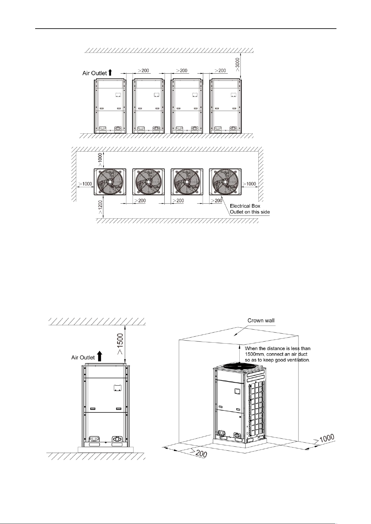
3.2.1.4 Installation space requirement for four modules
Heat Recovery DC Inverter Multi VRF Unit
Unit: mm
Figure 6
3.2.2 When there is wall (or similar obstruction) above the unit, keep the distance between
the unit top and the wall at least 3000mm or above. When the unit is located in an open
space with no obstruction from front, back, left and right, keep the distance between the
unit top and wall at least 1500mm or above (See Fig.7). When the distance is limited within
1500mm or the unit is not set in an open space, air return pipe is required to be installed in
order to keep good ventilation (See Fig.8).
Figure 7 Figure 8
8
Unit: mm
Heat Recovery DC Inverter Multi VRF Unit
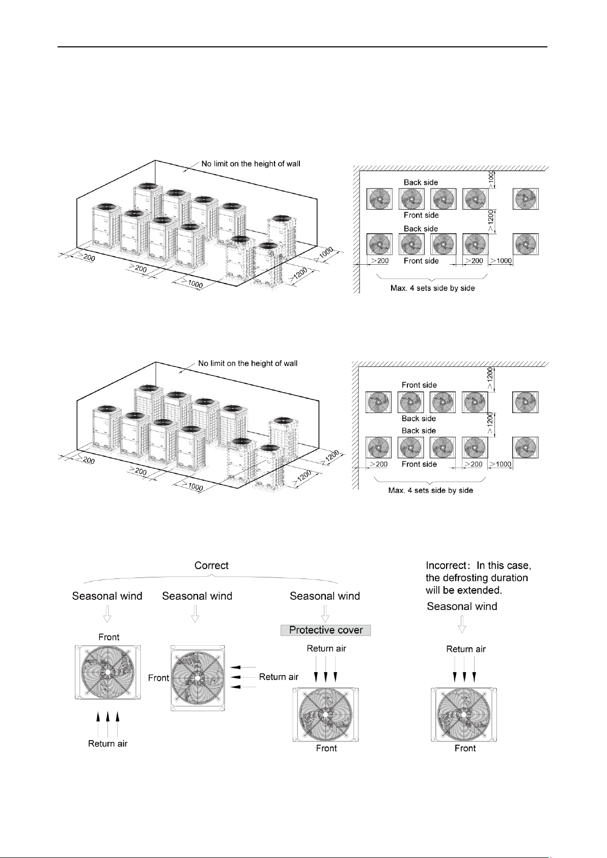
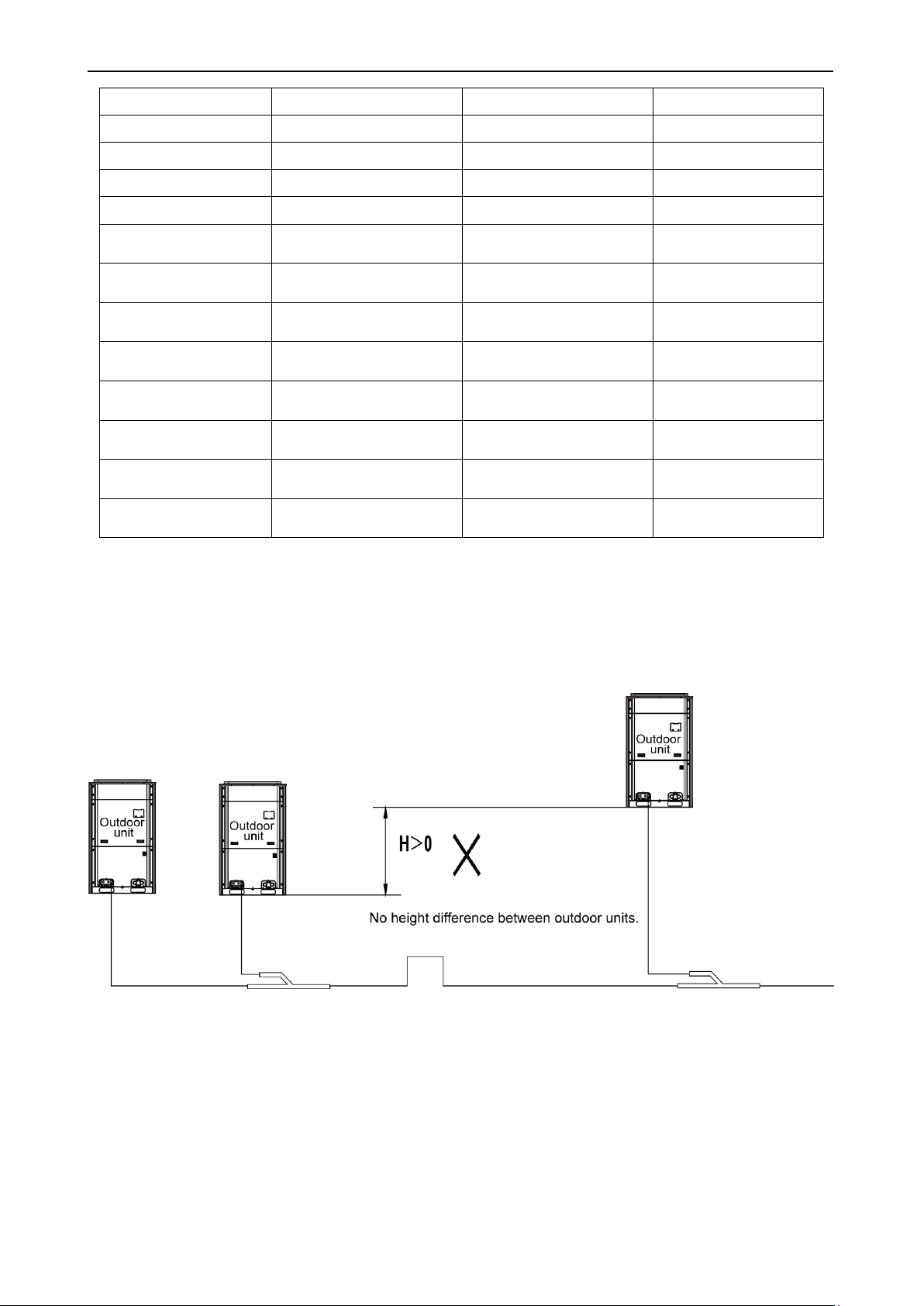
3.2.3 Installation space requirement for multiple outdoor units
In order to keep good ventilation, make sure there is no obstruction above the units.
When units are located in a semi-open space (front and left/right sides are open), install units as
per the same or opposite direction.
Figure 9
Figure 10
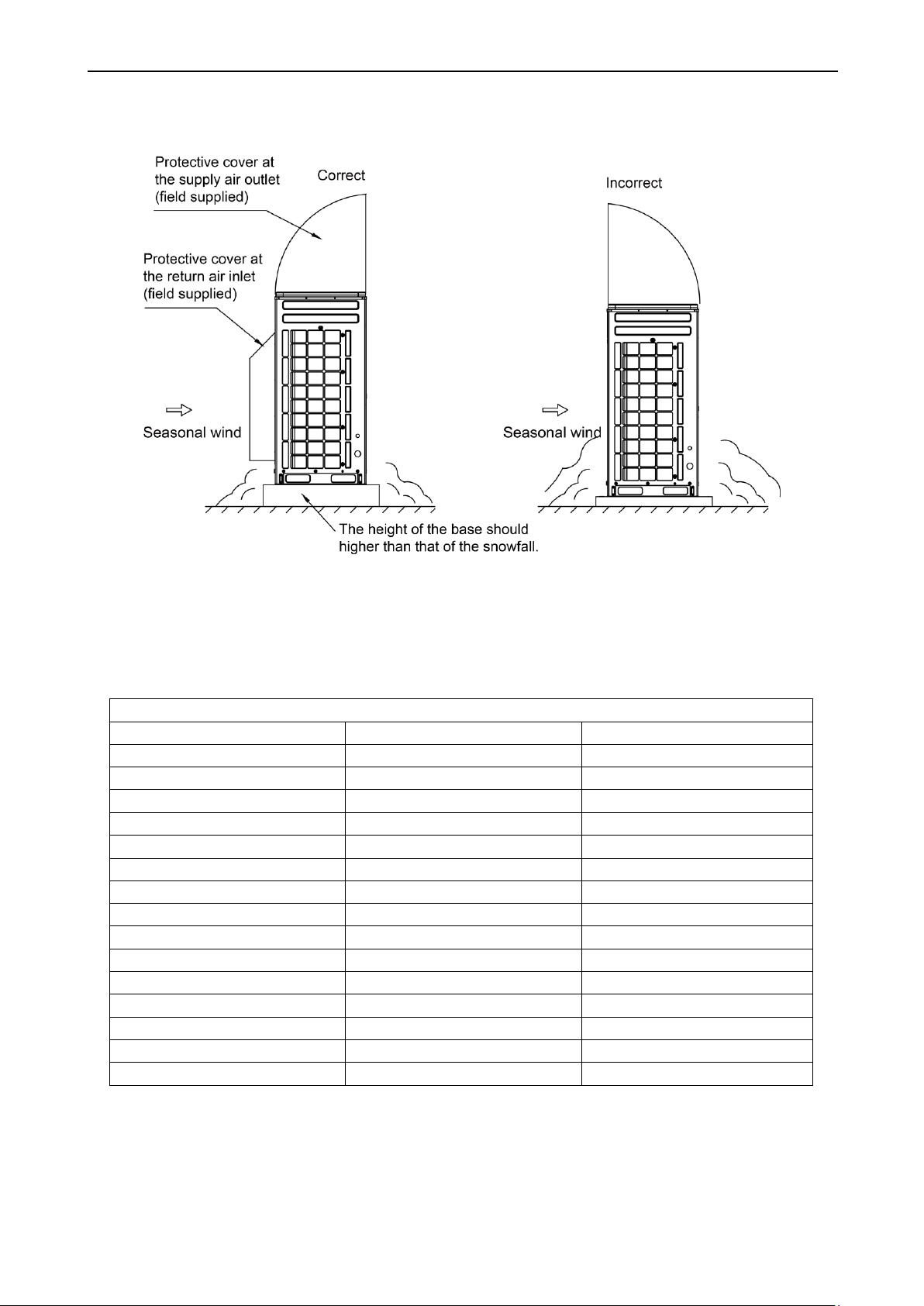
3.2.4 Take seasonal wind into consideration when installing outdoor units
Unit: mm
Unit: mm
Figure 11
9
Heat Recovery DC Inverter Multi VRF Unit
R410A Refrigeratn System
Outer diameter (mm/inch)
Wall thickness (mm)
Type
Φ6.35(1/4)
≥0.8
0
Φ9.52(3/8)
≥0.8
0
Φ12.70(1/2)
≥0.8
0
Φ15.9(5/8)
≥1.0
0
Φ19.05(3/4)
≥1.0
0
Φ22.2(7/8)
≥1.2
1/2H
Φ25.40(1/1)
≥1.2
1/2H
Φ28.60(9/8)
≥1.2
1/2H
Φ31.80(5/4)
≥1.3
1/2H
Φ34.90(11/8)
≥1.3
1/2H
Φ38.10(12/8)
≥1.5
1/2H
Φ41.30(13/8)
≥1.5
1/2H
Φ44.5(7/4)
≥1.5
1/2H
Φ51.4(7/4)
≥1.5
1/2H
Φ54.1(17/8)
≥1.5
1/2H
3.2.5 Take snow into considertaion when installation outdoor units
Figure 12
3.3 Connection Pipe Requirement
Refer to the table below for connection pipe requirement:
10
Heat Recovery DC Inverter Multi VRF Unit
4 Installation Instructions
Note: Graphics here are only for reference. Please refer to actual products. Unspecified dimensions
are all in mm.
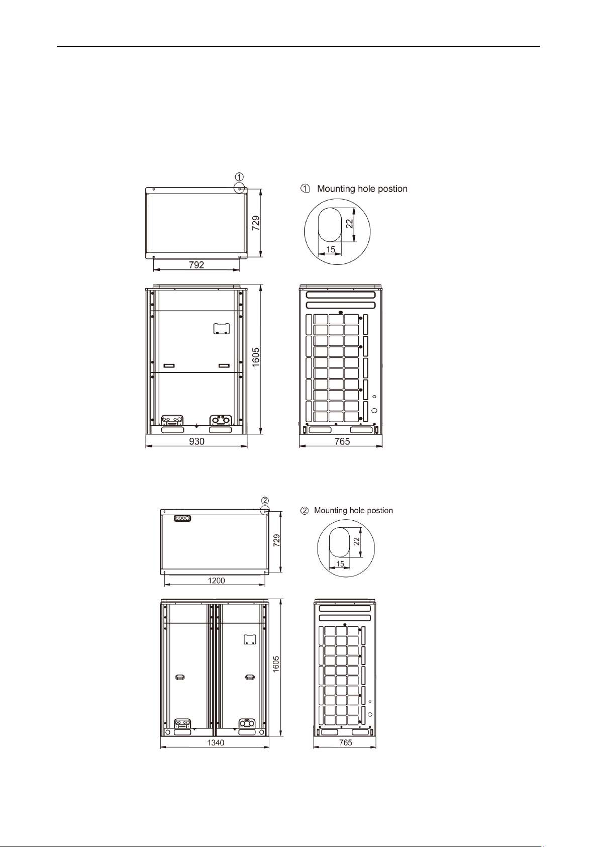
4.1 Dimension of Outdoor Unit and Mounting Hole
Outline and installation dimension of GMV-Q224WM/B-X, GMV-Q280WM/B-X
Unit: mm
Figure 13
Outline and installation dimension of GMV-Q335WM/B-X, GMV-Q400WM/B-X, GMV-Q450WM/B-X
Figure 14
11
Unit: mm
Heat Recovery DC Inverter Multi VRF Unit
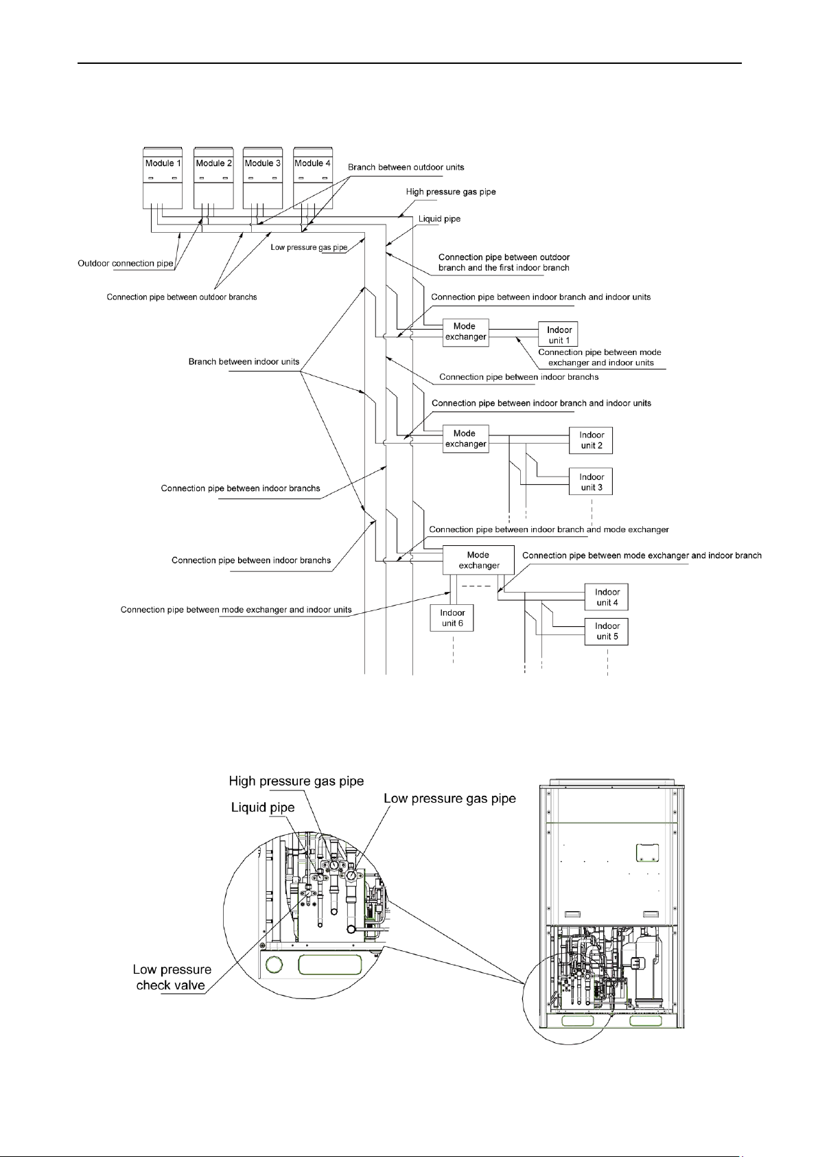
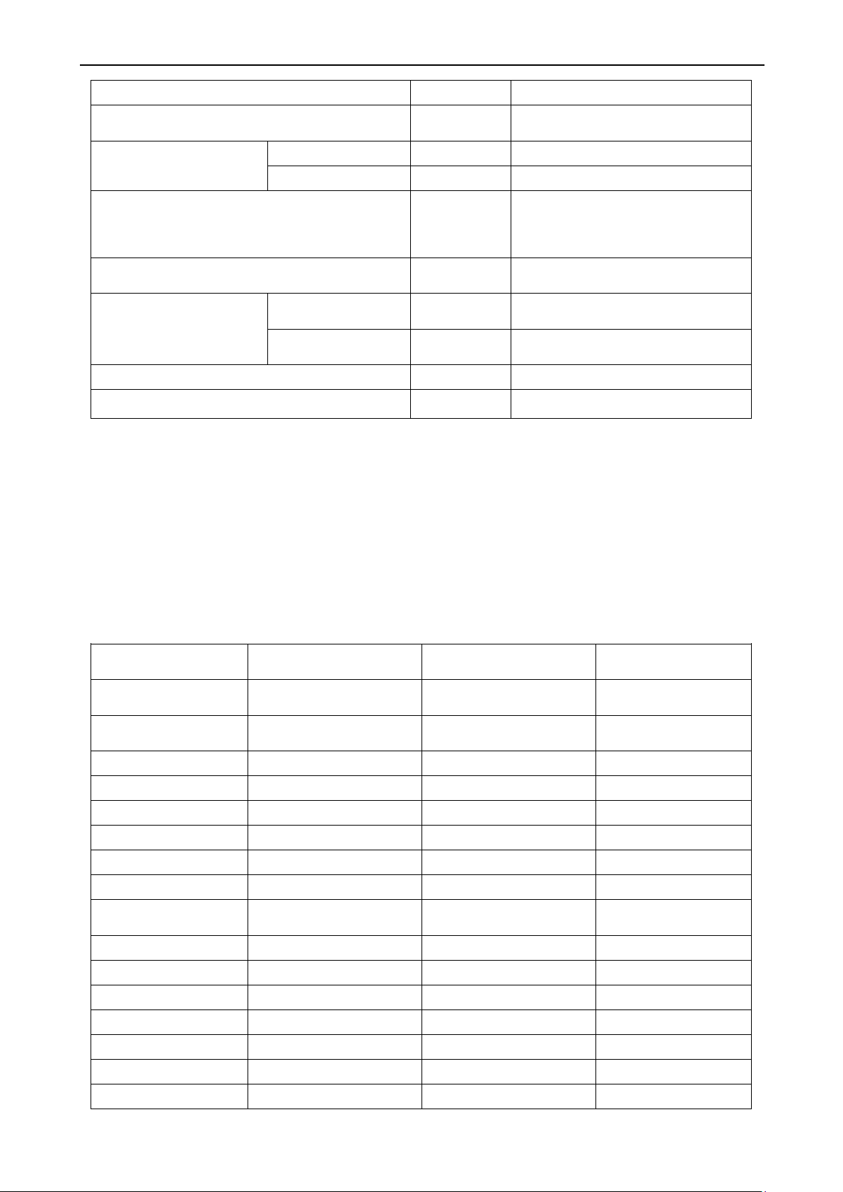
4.2 Refrigerant Connection Pipe of Indoor and Outdoor Units
4.2.1 Schematic diagram of piping connection
Figure 15
4.2.2 Schematic diagram of piping sequence
GMV-Q224WM/B-X, GMV-Q280WM/B-X
Figure 16
12

Heat Recovery DC Inverter Multi VRF Unit
GMV-Q335WM/B-X, GMV-Q400WM/B-X, GMV-Q450WM/B-X
Figure 17
4.2.3 Allowable pipe length and height difference between indoor and outdoor units
Y type branch joint is adopted to connect indoor and outdoor units. Connection method is shown
below:
Note: Length of one Y-type branch is equivalent to 0.5m.
Figure 18
Distance from the first branch to the farthest indoor unit;
Distance from the first branch to the nearest indoor unit;
Length of indoor branch is equivalent to 0.5m.
13
Length(m)
Remarks
Total length (actual length) of connection pipe
≤ 1000
L1+L2+L3+L4+…+L12+a11+b12+…+d2
1+d22
Length between outdoor unit
and the farthest indoor unit
Actual length
≤ 165
L
Equivalent length
≤ 190
Difference between the pipe length from the first
indoor branch to the farthest indoor unit and the pipe
length from the first indoor branch to the nearest
indoor unit
≤ 40
L12-L11
Length from the first indoor branch to the farthest
indoor unit (1)
≤ 40
L7+L8+L10+D22
Maximum height difference
between indoor and outdoor
units: H
Outdoor unit at upper
side
≤ 50
——
Outdoor unit at lower
side
≤ 90
——
Maximum height difference between indoor units: h
≤ 30
h1
Maximum length of Main pipe (2)
≤ 90
L1
Note:
Outdoor model
Diameter of low pressure
gas pipe (mm)
Diameter of liquid pipe (mm)
Diameter of high pressure
gas pipe (mm)
GMV-Q224WM/B-X
No need to enlarge pipe
diameter
No need to enlarge pipe
diameter
No need to enlarge pipe
diameter
GMV-Q280WM/B-X
No need to enlarge pipe
diameter
Φ12.7
Φ22.2
GMV-Q335WM/B-X
Φ28.6
Φ15.9
Φ22.2
GMV-Q400WM/B-X
Φ31.8
Φ15.9
Φ25.4
GMV-Q450WM/B-X
Φ31.8
Φ15.9
Φ25.4
GMV-Q504WM/B-X
Φ34.9
Φ19.05
Φ28.6
GMV-Q560WM/B-X
Φ34.9
Φ19.05
Φ28.6
GMV-Q615WM/B-X
Φ34.9
Φ19.05
Φ28.6
GMV-Q680WM/B-X
No need to enlarge pipe
diameter
Φ19.05
Φ28.6
GMV-Q730WM/B-X
Φ38.1
Φ22.2
Φ31.8
GMV-Q785WM/B-X
Φ38.1
Φ22.2
Φ31.8
GMV-Q850WM/B-X
Φ38.1
Φ22.2
Φ31.8
GMV-Q900WM/B-X
Φ38.1
Φ22.2
Φ31.8
GMV-Q960WM/B-X
Φ41.3
Φ22.2
Φ31.8
GMV-Q1010WM/B-X
Φ44.5
Φ22.2
Φ34.9
GMV-Q1065WM/B-X
Φ44.5
Φ22.2
Φ34.9
Heat Recovery DC Inverter Multi VRF Unit
Normally, the pipe length from the first indoor branch to the farthest indoor unit is 40m. Under
(1)
the following conditions, the length can reach 90m:
1)Actual length of pipe in total: L1+L2×2+L3×2+L4×2+…+L9×2+a11+b11+…+d21+d22≤1000m;
2)Difference between the pipe length from the first indoor branch to the farthest indoor unit and
the pipe length from the first indoor branch to the nearest indoor unit: L12-L11≤40m.
When the maximum length of the main pipe from outdoor unit to the first indoor branch ≥90m,
(2)
then adjust the size of high pressure gas pipe, gas pipe and liquid pipe of main pipe according
to the following table.
14
Heat Recovery DC Inverter Multi VRF Unit
GMV-Q1130WM/B-X
Φ44.5
Φ22.2
Φ34.9
GMV-Q1180WM/B-X
Φ44.5
Φ22.2
Φ34.9
GMV-Q1235WM/B-X
Φ44.5
Φ22.2
Φ34.9
GMV-Q1300WM/B-X
Φ44.5
Φ22.2
Φ34.9
GMV-Q1350WM/B-X
Φ44.5
Φ22.2
Φ34.9
GMV-Q1410WM/B-X
No need to enlarge pipe
diameter
Φ25.4
Φ41.3
GMV-Q1460WM/B-X
No need to enlarge pipe
diameter
Φ25.4
Φ41.3
GMV-Q1515WM/B-X
No need to enlarge pipe
diameter
Φ25.4
Φ41.3
GMV-Q1580WM/B-X
No need to enlarge pipe
diameter
Φ25.4
Φ41.3
GMV-Q1630WM/B-X
No need to enlarge pipe
diameter
Φ25.4
Φ41.3
GMV-Q1685WM/B-X
No need to enlarge pipe
diameter
Φ25.4
Φ41.3
GMV-Q1750WM/B-X
No need to enlarge pipe
diameter
Φ25.4
Φ41.3
GMV-Q1800WM/B-X
No need to enlarge pipe
diameter
Φ25.4
Φ41.3
If the length between indoor unit and its nearest branch is above 10m, then double the size of
(3)
the liquid pipe of indoor unit (only for the pipe size that is less than or equal to 6.35mm).
4.2.4 Pipe connection of outdoor modules
Figure 19
15
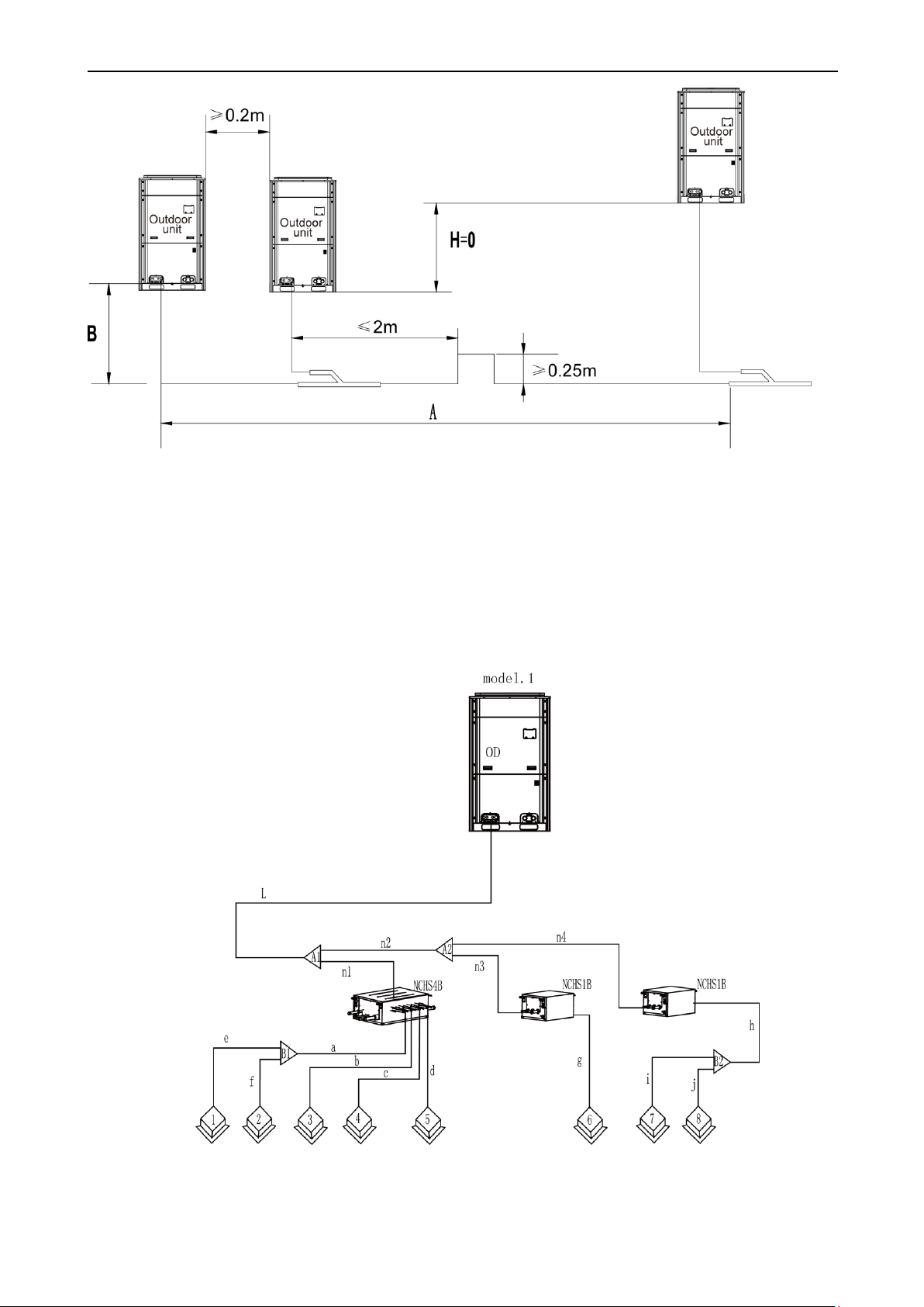
A+B ≤10m。
Heat Recovery DC Inverter Multi VRF Unit
Figure 20
Note: When the distance between outdoor units exceeds 2m, U-type oil trap should be added at
low pressure gas pipe. A+B≤10m.
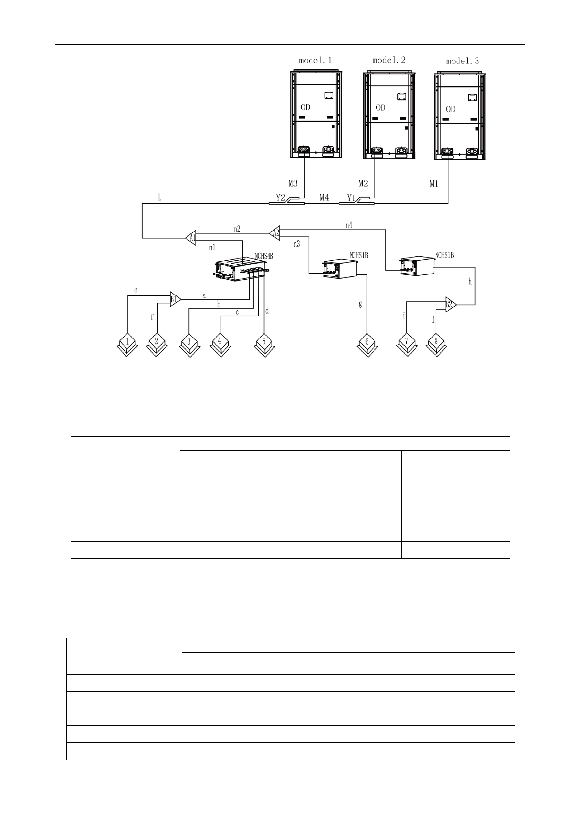
4.2.5 Size requirement for branch pipe and piping (main pipe)
4.2.5.1 Connection sketch map of single-module system
Figure 21
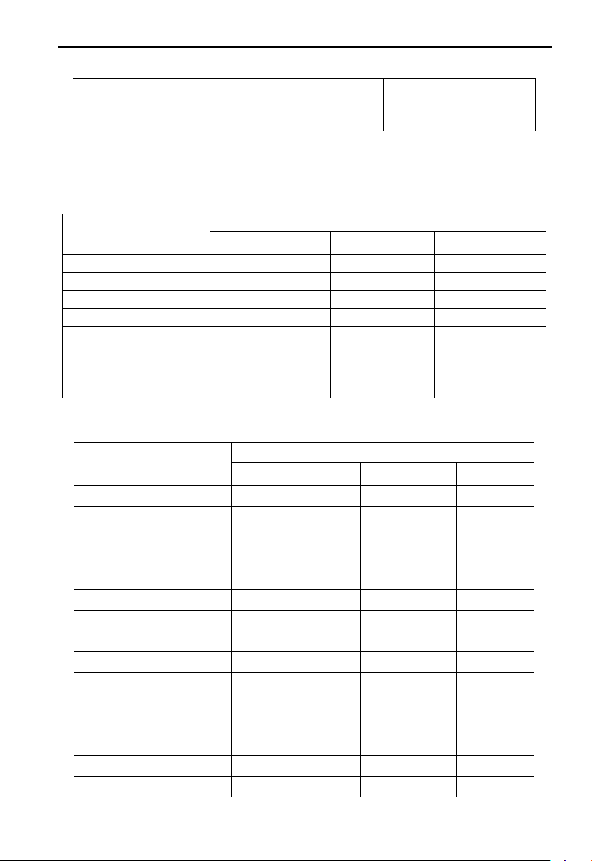
Connection sketch map of multi-module system
16
Heat Recovery DC Inverter Multi VRF Unit
Basic module
Pipe between outdoor unit and the first indoor branch
Low pressure gas pipe
(mm)
Liquid pipe (mm)
High pressure gas pipe
(mm)
GMV-Q224WM/B-X
Φ19.05
Φ9.52
Φ15.9
GMV-Q280WM/B-X
Φ22.2
Φ9.52
Φ19.05
GMV-Q335WM/B-X
Φ25.4
Φ12.7
Φ19.05
GMV-Q400WM/B-X
Φ25.4
Φ12.7
Φ22.2
GMV-Q450WM/B-X
Φ28.6
Φ12.7
Φ22.2
Basic module
Size of the pipe between module and outdoor branch
Low pressure gas pipe
(mm)
Liquid pipe (mm)
High pressure gas pipe
(mm)
GMV-Q224WM/B-X
Φ19.05
Φ9.52
Φ15.9
GMV-Q280WM/B-X
Φ22.2
Φ9.52
Φ19.05
GMV-Q335WM/B-X
Φ25.4
Φ12.7
Φ19.05
GMV-Q400WM/B-X
Φ25.4
Φ12.7
Φ22.2
GMV-Q450WM/B-X
Φ28.6
Φ12.7
Φ22.2
Figure 22
4.2.5.1 Select appropriate pipe between outdoor unit and the first indoor branch (“L”) as per the pipe
size of outdoor unit. Pipe size of basic outdoor module is shown as follows:
between outdoor unit and the first indoor branch
4.2.5.2 For multi-module system, select appropriate branch (”M1、M2、M3”)connected to outdoor
module as per the pipe size of basic outdoor module. Pipe size of basic outdoor module is shown as
follows:
Pipe between module and outdoor branch ”M1、M2、M3”
17
Heat Recovery DC Inverter Multi VRF Unit
Module’s capacity (C)
Model
Selection of branch of outdoor
modules
504≤C
ML01R
Total rated capacity of upstream
modules: Q (kW)
Size of connection pipe between branches of outdoor module
Low pressure gas pipe
(mm)
Liquid pipe (mm)
High pressure gas pipe
(mm)
22.4≥Q
Φ19.05
Φ9.52
Φ15.9
28.0≥Q
>
22.4
Φ22.2
Φ9.52
Φ19.05
40.0≥Q
>
28.0
Φ25.4
Φ12.7
Φ19.05
45.0≥Q
>
40.0
Φ28.6
Φ12.7
Φ22.2
68.0≥Q
>
45.0
Φ28.6
Φ15.9
Φ25.4
96.0≥Q
>
68.0
Φ31.8
Φ19.05
Φ28.6
135.0≥Q
>
96.0
Φ38.1
Φ19.05
Φ31.8
Q>135.0
Φ44.5
Φ22.2
Φ38.1
Basic module (single-module system)
Size of connection between outdoor unit and the first indoor branch
Low pressure gas pipe (mm)
Liquid pipe (mm)
High pressure gas
pipe (mm)
GMV-Q224WM/B-X
Φ19.05
Φ9.52
Φ15.9
GMV-Q280WM/B-X
Φ22.2
Φ9.52
Φ19.05
GMV-Q335WM/B-X
Φ25.4
Φ12.7
Φ19.05
GMV-Q400WM/B-X
Φ25.4
Φ12.7
Φ22.2
GMV-Q450WM/B-X
Φ28.6
Φ12.7
Φ22.2
GMV-Q504WM/B-X
Φ28.6
Φ15.9
Φ25.4
GMV-Q560WM/B-X
Ф28.6
Ф15.9
Φ25.4
GMV-Q615WM/B-X
Ф28.6
Ф15.9
Φ25.4
GMV-Q680WM/B-X
Ф28.6
Ф15.9
Φ25.4
GMV-Q730WM/B-X
Ф31.8
Ф19.05
Φ28.6
GMV-Q785WM/B-X
Ф31.8
Ф19.05
Φ28.6
GMV-Q850WM/B-X
Ф31.8
Ф19.05
Φ28.6
GMV-Q900WM/B-X
Ф31.8
Ф19.05
Φ28.6
GMV-Q960WM/B-X
Ф31.8
Ф19.05
Φ28.6
GMV-Q1010WM/B-X
Ф38.1
Ф19.05
Φ31.8
Selection of branch
“Y1、Y2”
4.2.5.3 Size of connection pipe
of outdoor modules:
”M4”
between branches of each basic module
Size of connection pipe between branches of each basic module is determined by the total rated
capacity of upstream modules.
Connection pipe ”M4” between branches of outdoor module
4.2.5.4 Size of connection pipe ”L” between the terminal outdoor branch and the first indoor branch
Connection pipe “L”between outdoor unit and the first indoor branch
18
 Loading...