

Page 1
INSTRUCTION MANUAL
SPECIFICATIONS
Wingspan:
56.5 in [1435 mm]
Length: 46 in [1170 mm]
Wing Area: 537in
2
[34.6dm2]
Weight:
Wing
Loading:
Radio: 4−5 Channel
WARRANTY
Great Planes® Model Manufacturing Co. guarantees this
kit to be free from defects in both material and workmanship at
the date of purchase. This warranty does not cover any
component parts damaged by use or modication. In no case
shall Great Planes’ liability exceed the original cost of
the purchased kit. Further, Great Planes reserves the right to
change or modify this warranty without notice.
In that Great Planes has no control over the nal assembly or
material used for nal assembly, no liability shall be assumed nor
accepted for any damage resulting from the use by the user of
the nal user-assembled product. By the act of using the
user-assembled product, the user accepts all resulting liability.
If the buyer is not prepared to accept the liability
associated with the use of this product, the buyer is
5 – 5.75 lbs [2270– 2610 g]
21– 25 oz /f t
2
Engine: .46−.55 cu in (7– 9 cc) 2-stroke
or .70 cu in (11.5 cc) 4 -stroke glow
[64–76 g/dm2]
Electric: RimFire .32, 4S 3300 mAh LiPo,
75 A ESC, 13 x 8E propeller
advised to return this kit immediately in new and
unused condition to the place of purchase.
To make a warranty claim send the defective part or item to
Hobby Services at the address below:
Hobby Services
3002 N. Apollo Dr. Suite 1
Champaign IL 61822 USA
Include a letter stating your name, return shipping address, as
much contact information as possible (daytime telephone
number, fax number, e-mail address), a detailed description of
the problem and a photocopy of the purchase receipt. Upon
receipt of the package the problem will be evaluated as quickly
as possible.
READ THROUGH THIS MANUAL BEFORE STARTING CONSTRUCTION. IT CONTAINS IMPORTANT
INSTRUCTIONS AND WARNINGS CONCERNING THE ASSEMBLY AND USE OF THIS MODEL.
© 2016 Great Planes Model Mfg. A subsidiary of Hobbico,® Inc.
Champaign, Illinois
(217) 398-8970, Ext 5
airsupport@greatplanes.com
GPMA1209
Page 2

TABLE OF CONTENTS
INTRODUCTION . . . . . . . . . . . . . . . . . . . . . . . . . . . . . . . .2
Know Before You Fly . . . . . . . . . . . . . . . . . . . . . . . . . . 2
ADDITIONAL ITEMS REQUIRED . . . . . . . . . . . . . . . . . .2
Radio / Servos . . . . . . . . . . . . . . . . . . . . . . . . . . . . . . .2
Glow Engine. . . . . . . . . . . . . . . . . . . . . . . . . . . . . . . . .2
Other Accessories for a Glow Engine . . . . . . . . . . . . .2
Brushless Electric Motor . . . . . . . . . . . . . . . . . . . . . . .3
LiPo Battery Charger. . . . . . . . . . . . . . . . . . . . . . . . . .3
ADHESIVES, HARDWARE AND
OTHER ACCESSORIES . . . . . . . . . . . . . . . . . . . . . . .3
KIT INSPECTION . . . . . . . . . . . . . . . . . . . . . . . . . . . . . . .3
REPLACEMENT PARTS LIST . . . . . . . . . . . . . . . . . . . . .3
KIT CONTENTS. . . . . . . . . . . . . . . . . . . . . . . . . . . . . . . . .4
PREPARATIONS . . . . . . . . . . . . . . . . . . . . . . . . . . . . . . . .4
ASSEMBLE THE WING . . . . . . . . . . . . . . . . . . . . . . . . . .5
ASSEMBLE THE FUSELAGE. . . . . . . . . . . . . . . . . . . . . .7
Install the Electric Motor . . . . . . . . . . . . . . . . . . . . . . .9
INTRODUCTION
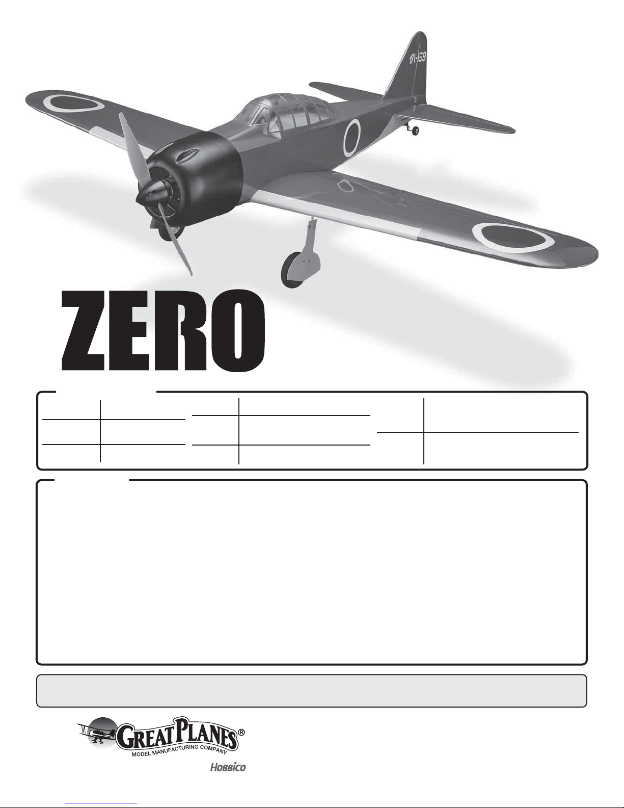
Congratulations and thank you for purchasing the Great
Planes “Zero” Sport Fighter ARF. The Sport Fighter series is
an easy start to scale modeling, but with practical, sport ying
characteristics and the durability of an every-day sport yer.
For the latest technical updates or manual corrections nd
the Sport Fighter Zero ARF page on the Great Planes Model
Manufacturing web site at www.greatplanes.com. If there is
new technical information or changes to this model a “tech
notice” box will appear on the page.
Know Before You Fly
As a new owner of an unmanned aircraft system (UAS), you
are responsible for the operation of this vehicle and the safety
of those around you. Please contact your local authorities
to nd out the latest rules and regulations.
In the United States, please visit:
Mount the Glow Engine . . . . . . . . . . . . . . . . . . . . . . . 12
Hook Up the Throttle . . . . . . . . . . . . . . . . . . . . . . . . . 13
Mount the Cowl . . . . . . . . . . . . . . . . . . . . . . . . . . . . .14
Install the Radio . . . . . . . . . . . . . . . . . . . . . . . . . . . . . 15
PREPARE THE MODEL FOR FLIGHT. . . . . . . . . . . . . . 16
Set the Control Throws . . . . . . . . . . . . . . . . . . . . . . . 16
Check the C.G. . . . . . . . . . . . . . . . . . . . . . . . . . . . . .17
Balance the Model Laterally . . . . . . . . . . . . . . . . . . . 17
PREFLIGHT . . . . . . . . . . . . . . . . . . . . . . . . . . . . . . . . . . .17
Engine/Motor Safety Precautions . . . . . . . . . . . . . . . 17
Battery Precautions. . . . . . . . . . . . . . . . . . . . . . . . . .19
Range Check . . . . . . . . . . . . . . . . . . . . . . . . . . . . . . .20
AMA SAFETY CODE. . . . . . . . . . . . . . . . . . . . . . . . . . . .20
General . . . . . . . . . . . . . . . . . . . . . . . . . . . . . . . . . . .20
Radio Control. . . . . . . . . . . . . . . . . . . . . . . . . . . . . . . 20
FLYING. . . . . . . . . . . . . . . . . . . . . . . . . . . . . . . . . . . . . . .20
❍ Tactic TR625 6-chanel receiver (TACL0625)
❍ HydriMax 4-cell 2000mAh NiMH receiver pack
(HCAM6321)*
❍ On-off receiver switch (TACM2000)*
*If powering your Zero with a brushless electric motor the BEC
in the ESC may be used to power your receiver and servos, so
no receiver battery or on/off receiver switch will be required.
Servos nowadays are smaller and stronger, so we’ve designed
the servo mounts in the Zero to accommodate mini servos.
Full-size servos may still be used simply by enlarging the
mounts with a hobby knife. Four or 5 servos are required
depending on whether your Zero is electric or glow-powered:
❍ Tactic TSX25 mini digital high-speed 2 ball bearing
servo (TACM0225)
OR
❍ Tactic TSX20 mini high-speed 2 ball bearing servo
(TACM0220)
OR
❍ Tactic TSX35 standard sport servo (TACM0235)
knowbeforeyou y.org faa.gov/uas
ADDITIONAL ITEMS REQUIRED
Radio / Servos
A minimum of 4-channels is required to y the Zero. The
Tactic TTX650 is recommended because of its simple, exible
computer programming and multiple model memory:
❍ Tactic TTX650 6-channel programmable radio
(TACJ2650)
If mixing the aileron servos through the radio electronically:
❍ (4) 6" [150mm] servo extensions (TACM2092) are
required for the aileron servos.
If mixing the servos with a Y-harness:
❍ (2) 6" [150mm] servo extensions (TACM2092)
and a Y-harness (FUTM4130) are required for the
aileron servos.
2
Page 3
Glow Engine
The Zero is suited for a .46 – .55 2-stroke or .70 4-stroke. The
O.S. Max .55AX (O SM G0557) is illustrated in this manual with
a Bisson Pitts-style muf er (BISG4046).
Other Accessories for a Glow Engine
❍ 1/4" [6.4mm] R/C foam rubber (HCAQ1000)
❍ Great Planes Dead Center Hole Locator (GPMR8130)
❍ 6-32 tap and drill set (DUBR0510)
❍ Suitable propeller for your engine
Brushless Electric Motor
The electric setup for the Zero is straightforward: a Great
Planes ElectriFly RimFire .32 on a 13 x 8 E prop with a minimum
60A ESC powered by a 4S battery in the 3300 mAh – 4000mAh
range*. A Castle Creations Edge Lite 75 was selected and is
illustrated in the instruction manual because it is compact,
easily programmable and features data logging.
❍ 42-50-800 RimFire .32 (GPMG4700)
❍ APC 13 x 8 thin E prop (APCQ3080)
❍ Castle Creations Edge Lite 75 (CSEM1200)
❍ FlightPower 4S 3300 mAh 25C (FPWP2334)
OR
❍ FlightPower 4S 4000 mAh 25C (FPWP2404)
❍ 3/16" heat shrink tubing (GPMM1056)
❍ T-style Star connector (HCAM4001)
* Other propeller options are noted on page 19.
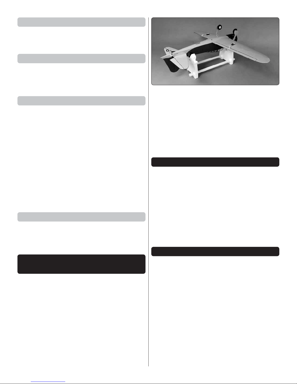
A Robart Super Stand II (ROBP1402) is also indispensable
for working on your Zero.
A covering iron with a cover sock may be required for
tightening and re bonding the covering to the model that may
have loosened between the time the plane was manufactured
and the time the model was removed from the box. The 21st
Century iron is preferred because of its long cord, contoured
shoe and precisely adjustable temperature range:
❍ Coverite 21st Century Sealing Iron (COVR2700)
❍ Coverite 21st Century Cover Sock (COVR2702)
KIT INSPECTION
Before starting to build, take an inventory of this kit to make
sure it is complete, and inspect the parts to make sure
they are of acceptable quality. If any parts are missing or
are not of acceptable quality, or if you need assistance
with assembly, contact Product Support. When reporting
defective or missing parts, use the part names exactly as
they are written in the Kit Contents list.
LiPo Battery Charger
To charge a 4S 4000mAh LiPo at 1C, a charger capable of
at least 70 watts is required (4S x 4.2V/cell = 16.8V x 4A =
67 watts). The Triton2 EQ is more than enough charger with
100 W output AC and 120 W output DC (GPMM3156).
ADHESIVES, HARDWARE AND
OTHER ACCESSORIES
Other than common hobby tools here is a list of the rest of
the items required:
❍ 30-minute epoxy (GPMR6043)
❍ Epoxy brushes (GPMR8060)
❍ Mixing cups (GPMR8056)
❍ Mixing sticks (GPMR8055)
❍ Threadlocker thread locking cement (GPMR6060)
❍ Thin CA (GPMR6001)
❍ Medium CA (GPMR6007)
❍ CA applicator tips (HCAR3780)
❍ Optional: Scale Military Pilot (GPMQ9117)
Great Planes Product Support
3002 N Apollo Drive, Suite 1 Ph: (217) 398-8970, ext. 5
Champaign, IL 61822 Fax: (217) 398-7721
E-mail: airsupport@greatplanes.com
REPLACEMENT PARTS LIST
GPMA5395 Wing
GPMA5396 Fuselage
GPMA5397 Tail Surface Set
GPMA5398 Cowl
GPMA5399 Spinner
GPMA5400 Landing Gear Set
GPMA5401 Gear Covers
GPMA5402 Canopy
GPMA5403 Decals
GPMA5404 EP Motor Mount Parts
GPMA5405 Belly Pan
3
Page 4
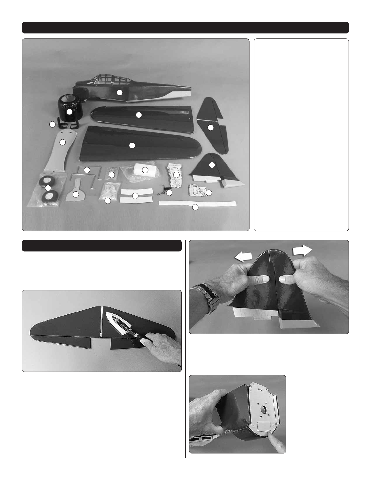
KIT CONTENTS
1. Fuselage w/ Canopy Hatch
2. Cowl
3. Engine Mount
4. Wings
1
2
3
7
10
8
9
11
12
4
5
4
14
13
15
16
6
18
17
5. Horizontal Stab
6. Vertical Stab
7. Belly Pan
8. Main Wheels
9. Wheel Covers
10. Main Landing Gear Wires
11. H a r d w a r e
12. Nylon Hardware
13. Wing Joiner
14. Fuel Tank
15. EP Motor Mount Box
16. Tail Gear
17. Velcro Strap
18. Laser-cut Wood Parts
PREPARATIONS
Note: The covering on your Zero requires less heat than you
may be used to if you’re already familiar with iron-on coverings
– too much heat causes seams and edges to draw away from
each other causing wavy, uneven edges or exposed balsa.
1. Use a covering iron with a cover sock to tighten any
❏
loose covering. Wherever the covering is over wood (especially
on the sheet balsa tail surfaces) press down on the iron to
make sure the covering is thoroughly bonded to the balsa
underneath. The optimum temperature measured on the
surface of the cover sock is about 280F [140C] which requires
a dial setting of about 300F [150C] or “medium” heat on
most covering irons. If the covering blisters up over balsa
and cannot be pressed back down, the iron may be too hot
or you are leaving it in one location for too long—try reducing
the heat or moving the iron a little faster.
2. Give a generous tug on all control surfaces to check the
❏
hinges. Add thin CA where necessary to any loose hinges.
Residual CA or CA “fog” is removable with a paper towel
square dampened with CA debonder.
3. If powering
❏
your Zero with a glow
engine, apply a lm of
epoxy or CA to edges
of the covering around
the nose and rewall
to seal from fuel and
exhaust residue.
4
Page 5
ASSEMBLE THE WING
Cut out
Enlarge the aileron
servo mount as necessary
to t your servos.
1/8" [ 3 mm ]
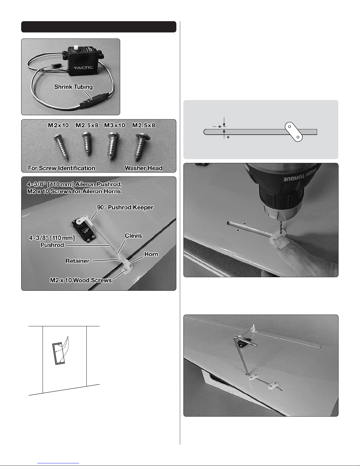
1. Attach a 6"
❏
[150mm] servo
extension to each
aileron servo and
secure with the
included 3" [75mm]
shrink tubing cut
into two 1-1/2"
[40mm] pieces.
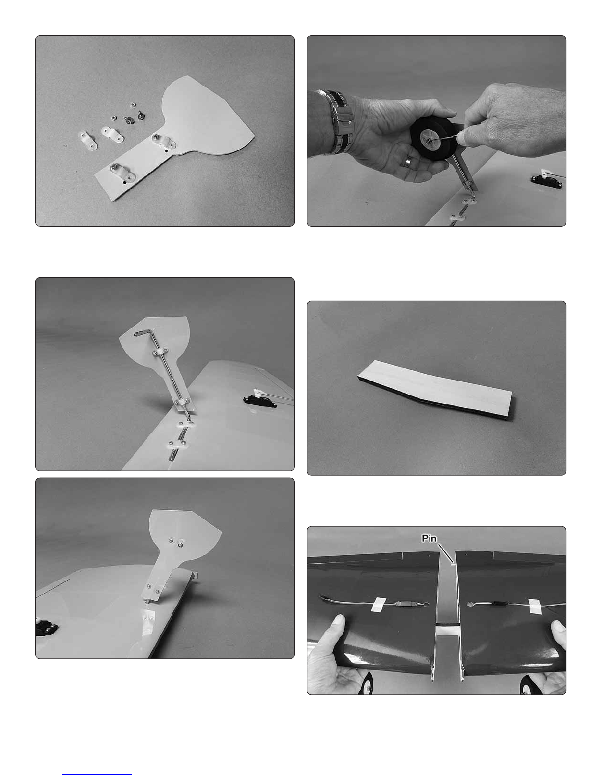
4. Drill 1/16" [1.6mm] holes for the servo mounting screws
❏
in the wing and for the control horn screws on the aileron
(use care not to drill through the top of the aileron). Mount the
servo and horn, make the pushrod and hook up the aileron
using the hardware shown.
5. After mounting the aileron horns, remove the screws,
❏
harden the holes with a few drops of thin CA, allow to harden,
and then reinstall the screws.
6. Hook up the aileron servo in the right wing the same way.
❏
Refer to this image while mounting the aileron servos
and hooking up the ailerons.
Do the left wing rst…
2. If necessary, enlarge the servo cutout to t your servo.
❏
3. Use the string to pull the aileron servo wire through
❏
the wing (or just guide the servo wires down through the
holes without using the string) and t the servo into the
servo openings.
7. Use a at landing gear strap as a guide to drill 3/32"
❏
[2.4 mm] holes into the landing gear block in the left wing–
angle the straps so the holes will be 1/8" [3mm] from the
edge of the groove.
8. Mount the main landing gear to the rails with two straps
❏
and four M3 x 10 screws.
5
Page 6
9. Use two M2 x 8 machine-thread screws, washers, M2
❏
nuts and a little threadlocker to loosely fasten two hump
straps to the outside of one of the wheel covers.
12. Lightly wet the threads of four M3 set screws with
❏
threadlocker and mount the main wheels to the main landing
gear wire with a wheel collar on both sides—a 1.5mm
machined hex driver is recommended for securely tightening
the set screws (rather than a stamped “L” hex key wrench).
13. Glue together both pieces of the plywood wing
❏
joiner—epoxy may be used to provide more working time
for alignment, or CA may be used for faster assembly.
10. Fasten the cover to the landing gear wire with two
❏
more screws, washers, nuts and threadlocker and tighten
all the screws.
11. Mount the other landing gear, wheel and cover to the
❏
right wing the same way.
14. Once the glue on the joiner halves has hardened, test-
❏
t the wings together with the joiner and the nylon alignment
pin. Make any adjustments necessary for a good t.
6
Page 7
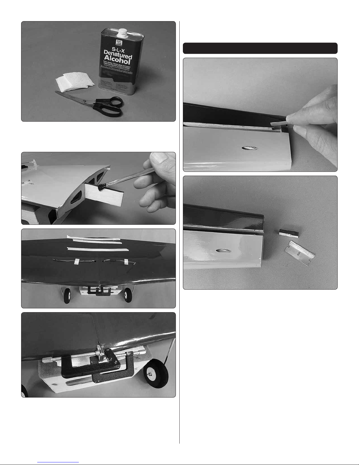
15. A few paper towels cut into small squares and denatured
❏
alcohol will be useful for cleaning off excess epoxy during the
next step while gluing the wing halves together.
17. After the epoxy has hardened remove the clamps
❏
and tape.
ASSEMBLE THE FUSELAGE
16. Apply 30-minute epoxy to all joining surfaces including
❏
the root ribs and the “Joiner Pockets” inside the wings where
the joiner goes. Securely hold the wing halves together with
masking tape and small clamps or clips on the tabs. As you
proceed, use paper towel squares dampened with denatured
alcohol to wipe away excess epoxy.
1. Cut and remove the spacer from the slot for the horizontal
❏
stabilizer at the back of the fuselage.
2. Mount the wing to the fuselage with two 10-24 x 2" nylon
❏
wing bolts (for convenience, you may shorten the wing bolts
by cutting them to a length of 1-1/2" [40 mm ]).
7
Page 8
5. Remove the stab and n from the fuselage. Use
❏
30-minute epoxy to glue the tail gear wire into the rudder
and glue the stab and n into the fuselage. Use more paper
towel squares dampened with denatured alcohol to wipe
away residual epoxy. If any weight was required to level the
stab with the wing don’t forget to reposition the weight and
double-check the alignment before the epoxy hardens.
3. Test t the tail gear wire into the rudder and t the vertical
❏
and horizontal stabilizers into the fuselage.
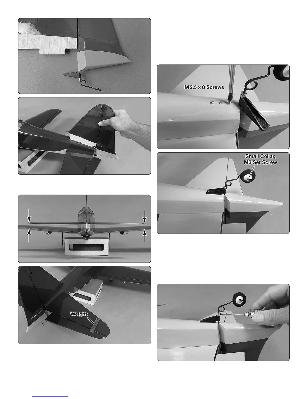
6. Use the holes in the tail gear bracket as a guide to
❏
drill 1/16" [1.6mm] holes into the bottom of the fuselage for
the mounting screws. Screw three M2.5 x 8 screws into the
holes, remove the screws, add a few drops of thin CA to the
holes, allow to fully harden, then mount the gear bracket to
the fuse with the screws. Mount the tail wheel with a small
collar and a M3 set screw and threadlocker.
4. View the model from behind and check the alignment
❏
between the horizontal stabilizer and the wing. If necessary,
adjust the slot in the fuselage to get the stab horizontally
aligned with the wing—in most cases, all that will be required
is a small amount of weight on the high side of the stab.
7. Tighten the collar up against the tail gear bracket with
❏
an M3 set screw wetted with threadlocker.
8
Page 9

8. Use medium-grit sandpaper to roughen the ange on
❏
the belly pan and remove any minute inconsistencies so glue
will adhere. Test- t the belly pan to the bottom of the wing
and make any adjustments necessary for a good t.
9. With the belly pan in position, tape one side down to
❏
the wing. Use thin CA dispensed through a ne tip to glue the
other side of the belly pan to the wing—little CA is required and
use care not to apply too much CA at the front and back of
the belly pan so excess will not glue the wing to the fuselage.
11. Carefully trim the corners of the belly pan that protrude
❏
beyond the fuselage and the wing.
If installing a glow engine skip to Mount the Glow Engine
on page 12.
Install the Electric Motor
10. Remove the tape and glue the other side of the belly
❏
pan to the wing. After the CA has hardened, a paper towel
square dampened with CA debonder may be used to wipe
off any excess CA or CA fog.
1. Glue together both pieces of the front plate and the
❏
back plate for the EP motor mount box alternating the wood
grain direction of each set. NOTE: These parts may already
be glued together by the factory.
9
Page 10

2. Press 4-40 blind nuts into the front plate and glue them
❏
in with CA.
3. With the blind nuts on the inside of the assembly, glue
❏
all the motor mount box parts together—it’s quick and easy
just to hold the assembly together while gluing it with thin CA.
5. Drill 1/16" [1.6mm] pilot holes through the “O” marks
❏
in the rewall, then enlarge the holes with a 5/32" [4mm] drill.
Insert 6-32 blind nuts into the back of the holes.
6. Cut the rest of the way through the partially cut air inlet
❏
in the rewall and remove the piece.
4. Glue the triangle stock reinforcements around the front
❏
and back plates—it’s easy to position them with a hobby
blade and glue them down with medium CA.
7. Mount the motor mount box to the rewall with four 6-32
❏
x 3/4" Phillips screws and #6 lock washers and at washers
and threadlocker.
10
Page 11

8. Assemble the motor and mount it to the motor mount
❏
box with four 4-40 x 1/2" Phillips screws and #4 lock washers
and at washers and threadlocker—notice that the motor
wires are positioned on the left side for a smooth connection
to the ESC.
9. Connect your ESC to the motor and mount the ESC to
❏
the bottom of the motor mount box—for the Castle Creations
Edge Lite 75 ESC we soldered the female bullet connectors
that came with the motor to the three motor wires (protected
with 3/16" heat shrink tubing) and a Star connector to the
battery wires, then mounted the ESC to the box with a piece
of foam rubber and nylon ties.
11. Glue the two balsa sticks across the back of the
❏
rewall so the screws don’t puncture the LiPo battery in the
event of a crash.
10. Power up the ESC and use the transmitter to run
❏
the motor to make sure it turns the correct direction. If the
motor turns the wrong direction swap any two of the three
motor wires.
12. Attach the rougher, “hook” side of the included
❏
adhesive-back Velcro® strip to the battery mount plate and
the other, softer “loop” side to your battery.
11
Page 12

13. Test-mount your battery with a battery strap made
❏
from the included Velcro strips.
Skip to Install the Radio on page 15.
Mount the Glow Engine
The instructions illustrate installation of an O.S. Max .55 AX
with a Bisson No. 04046 Pitts-style muf er. If using a different
engine and/or a different muf er, slight adjustments may be
required in the way your engine is rotated on the rewall,
but as long as you align the four engine mount screws with
the circle inscribed on the rewall, the engine will be in the
correct location.
14. Mount the cowl with four 4-40 x 1/2" screws and #4
❏
washers and lock washers—the two screws in the top go in
through the front of the cowl and the two screws in the bottom
go in from the back inside the fuselage. For safety reasons,
do not mount the propeller until instructed to do so after the
radio has been set up and the control throws have been set.
1. Drill 1/16" [1.6 mm] pilot holes through the “X” marks in
❏
the rewall, then enlarge the holes with a 5/32" [4mm] drill. If
using an engine or muf er other than the O.S. .55AX/Bisson
Pitts-style muf er, the engine mount may need to be rotated
differently around the circle embossed in the rewall. However
you orient your engine, be sure to keep all four engine mount
holes on the circle embossed in the rewall so your engine
and mount will be positioned properly.
2. Insert 6-32 blind nuts into the holes in the back of the
❏
rewall.
3. Cut the “spreader bar” from both halves of the included
❏
engine mount and trim off any remaining material so they t
together well.
15. Cut the covering from the air passage slots in the
❏
bottom of the fuselage.
4. Temporarily mount the engine mount with four 6-32 x 1"
❏
screws and lock washers and at washers, but don’t tighten
the screws all the way yet.
12
Page 13

5. Place the back plate of the spinner on the engine and
❏
position the engine on the mount so the back plate will be 5"
[125 mm] from the rewall. Tighten the engine mount screws
and hold the engine in place with a clamp. Use a Great Planes
Dead-Center Hole Locator or similar tool to mark the engine
mount bolt hole locations onto the mount.
Hook Up the Throttle
1. If necessary, enlarge the cutout in the throttle servo
❏
tray to t your servo. Determine which side of the fuselage
works best for the throttle servo to align with the arm on the
carburetor, then glue the parts together to t that side.
6. Remove the engine and drill #36 (.106" [2.7mm]) holes at
❏
the marks, then tap 6-32 threads into the holes—if available,
a drill press is preferred for drilling the holes and the tap may
be chucked in a hand drill to tap the threads.
7. Mount the engine to the mount with four 6-32 x 3/4"
❏
Phillips screws and #6 lock washers.
2. Mount the throttle servo in the servo tray.
❏
3. Glue the throttle servo tray into the side of the fuselage
❏
that aligns with the carb arm.
4. Use the pattern on page 20 to make the throttle pushrod
❏
from the 2-56 x 19-3/4” [500 mm] pushrod.
13
Page 14

Mount the Cowl
The following instructions illustrate how to mount the cowl
and cut the muf er exhaust holes with the included template
for the O.S. Max .55AX with the Bisson muf er. If using a
different engine and/or muf er, mount the muf er to the
engine rst, then cut the cowl as necessary for the muf er
and the exhaust opening.
A No. 569 or 570 Dremel grout removal bit and a
sanding drum are indispensable for accurately cutting
a cowl. Always wear eye and breathing protection
when cutting fiberglass.
5. Install the throttle pushrod and connect it to the throttle
❏
servo. Bend the front of the pushrod as necessary to connect
to the screw-lock connector on the carburetor arm with a
screw-lock retainer.
6. Make a fuel tank strap by cutting one of the Velcro
❏
strips to a length of 6" [150mm] and the other strip to 7-1/2"
[190mm]. Hook the straps together overlapping 2" [50mm].
7. Install the fuel tank with a 2-1/2" x 5" [60 x 125mm]
❏
sheet of foam rubber on top of the fuel tank plate and secure
the tank with the strap.
1. Mount the cowl with four 4-40 x 1/2" [12mm] screws and
❏
#4 washers and lock washers—the two top cowl mounting
screws go into the front of the cowl ring and the bottom two
screws go in from the back inside the fuselage.
14
Page 15

4. Use compressed air or warm, soapy water to thoroughly
❏
clean all metal lings from the muf er. Mount the muf er to
the engine and mount the cowl to the fuselage enlarging the
exhaust cutouts as necessary to install the cowl over the
muf er tubes.
5. Cut any more holes in the cowl necessary for the needle
❏
valve, fueling line, glow plug igniter, etc.
6. Once all the holes are cut in the cowl, smooth any
❏
rough edges and remove loose bers with 320-grit, then
400-grit sandpaper.
Install the Radio
1. Make the elevator and rudder pushrods as shown.
❏
2. Cut the muf er cutout template for the Bisson muf er
❏
from the back of the manual and tape it into position as shown.
Mark the exhaust tube holes on the cowl, remove the cowl
and cut the holes.
3. Use a reinforced cutoff wheel (or other suitable tool
❏
for cutting aluminum) to cut the exhaust tubes to a length
of 1-3/4" [45mm]. This length will allow the exhaust tubes
to protrude from the cowl far enough to direct most of the
exhaust away from the bottom of the model, but still allow
the cowl to t over the tubes. Deburr the ends of the tube
with a metal le or sandpaper and a hobby knife.
2. Install the pushrods into the guide tubes in the fuselage.
❏
Drill 1/16" [1.6mm] holes into the rudder and through the
elevator for the horn screws. Mount the rudder horn with
two M2 x 10 screws and mount the elevator horn with two
M2 x 12 machine-thread screws and the horn mount plate.
15
Page 16

3. Remove the screws from the rudder horn, harden the
1/16" [1.5 mm]
Servo Arm
❏
screw holes with a few drops of thin CA, allow to harden,
then reinstall the screws.
4. If necessary, enlarge the cutout in the servo tray to
❏
t your servos, then install the servos in the tray but don’t
screw them down yet. Center the rudder and elevator and
the servos. Mark the pushrods where they cross the holes
in the servo arms.
6. If using a receiver battery for a glow engine, the battery
❏
may be mounted on top of the optional battery tray. The tray is
mounted with four M2.5 x 8 washer-head Phillips wood screws.
7. Apply the decals – the best way is to peel a decal from
❏
the sheet, spray the back with window cleaner, position the
decal, then squeegee out the window cleaner with a small
balsa sheet. This technique allows for precise positioning
and eliminates air bubbles.
Install a Pilot (Optional)
5. Disconnect the clevises from the horns and remove the
❏
pushrods from the fuselage. Make a 90-degree bend in each
wire at the marks. Fit each pushrod to a servo arm, install
a 90-degree pushrod keeper, cut off the excess wire, then
reinstall and connect the pushrods (this will require temporary
removal of the clevises).
A Great Planes 1/7-scale painted military pilot was used
(GPMQ9117).
1. Cut and remove the pilot base from the cockpit oor.
❏
Place your pilot onto the base and test- t inside the cockpit
to make sure he ts. Trim the pilot as necessary.
2. Fasten the pilot to the base with CA or screws.
❏
16
Page 17

3. Glue strips of
❏
balsa to the base
serving as tabs
for alignment – be
certain the tabs do
not interfere with
the t of the canopy
hatch to the fuselage.
Note: the throws are measured at the widest part of the
aileron, elevator and rudder.
These are the recommended control surface throws:
HIGH
ELEVATOR
Up & Down
AILERONS
Up & Down
LOW
3/8 in. [10 mm ] 11°
1/4 in. [6 mm ] 11°
5/8 in. [16 mm ] 19°
1/2 in. [ 13 mm ] 21°
4. Glue the pilot base back onto the cockpit oor.
❏
PREPARE THE MODEL FOR FLIGHT
Set the Control Throws
In addition to the C.G., the control throws have a major effect
on how the model ies and whether or not your rst ight will
be successful. Do not skip this important step and make sure
the throws are within the speci ed range. If necessary, use
programming in your transmitter and/or change the locations
of the pushrods in the servo arms and/or control horns to
adjust the throw.
RUDDER
Right & Left
1 in. [ 25 mm ] 12°
1-3/4 in. [44 mm] 21°
Check the C.G.
Same as the control throws, the C.G. has a great effect on how
the model ies. If the C.G. is too far forward the model may
be too stable and unresponsive to control inputs. If the C.G.
is too far aft the model may be too responsive and instable.
1. The model should be completely ready to y with all
❏
components installed (and an empty fuel tank if using a
glow engine).
Use a box or something similar to prop up the fuselage so the
horizontal stabilizer will be level. Check and set the control
throws according to the measurements on the next page:
2. If building the electric version, install the propeller and
❏
spinner and install the motor battery.
17
Page 18

75 mm
100 mm
3"
4"
Fuselage sides
The recommended C.G. is 3"− 4" [75 mm −100 mm]
back from the leading edge of the wing where it meets
the fuselage.
3. Use a Great Planes C.G. Machine to balance the model
❏
according to the measurements speci ed in the illustration,
or mark the balance range on the top of the wings and lift
it upside-down with your ngertips. As long as the model
balances anywhere within the speci ed range it is acceptable
(but less-experienced pilots should perform rst ights with
the Zero balanced in the middle or forward half of the range,
slightly nose heavy).
4. If the Zero doesn’t balance where speci ed, move the
❏
receiver battery or motor battery or add stick-on lead ballast
to the nose or tail to achieve the correct C.G.
5. If you’ve made any adjustments by adding ballast or
❏
moving components, check the C.G. again before ying.
Balance the Model Laterally
1. Lift the Zero several times by the propeller shaft and
❏
the tail to see if one wing drops.
2. If one wing drops consistently, add weight to the opposite
❏
tip by sticking it to the outside or strategically concealing
it inside the balsa tip. An airplane that has been laterally
balanced will track better in ight and maintain its heading
better during maneuvers when the plane is climbing.
PREFLIGHT
Engine/Motor Safety Precautions
Failure to follow these safety precautions may result in
severe injury to yourself and others.
● Keep all engine fuel in a safe place, away from high heat,
sparks or ames, as fuel is very ammable. Do not smoke
near the engine or fuel; and remember that engine exhaust
gives off a great deal of deadly carbon monoxide. Therefore
do not run the engine in a closed room or garage.
● Get help from an experienced pilot when learning to operate
engines.
● Use safety glasses when starting or running engines.
● Do not run the engine in an area of loose gravel or sand;
the propeller may throw such material in your face or eyes.
● Keep your face and body as well as all spectators away
from the plane of rotation of the propeller as you start and
run the engine.
● Keep these items away from the prop: loose clothing, shirt
sleeves, ties, scarfs, long hair or loose objects such as
pencils or screwdrivers that may fall out of shirt or jacket
pockets into the prop.
● Use a “chicken stick” or electric starter to start the engine.
Do not use your ngers to ip the propeller. Make certain
the glow plug clip or connector is secure so that it will not
pop off or otherwise get into the running propeller.
● Make all engine adjustments from behind the rotating
propeller.
● The engine gets hot! Do not touch it during or right after
operation. Make sure fuel lines are in good condition so
fuel will not leak onto a hot engine, causing a re.
● To stop a glow engine, cut off the fuel supply by closing
off the fuel line or following the engine manufacturer’s
recommendations. Do not use hands, ngers or any other
body part to try to stop the engine. To stop a gasoline
powered engine an on/off switch should be connected to
the engine coil. Do not throw anything into the propeller
of a running engine.
WARNING: For brushless electric motors, never have the
motor battery connected to the ESC without the transmitter
turned on – after each ight (or any time after running the
motor) always disconnect the battery before turning off
the transmitter. And when ready to y (or whenever running
the motor for any reason), always turn on the transmitter
rst before connecting the motor battery.
Also make certain your failsafe is programmed correctly
so in the event the receiver ever loses signal (or, if you
inadvertently turn off the transmitter before disconnecting
the battery or vice-versa) the motor will not turn. Follow
the instructions that came with your radio control system
to check and set the failsafe.
18
Page 19

The recommended RimFire .32 is rated for 50A constant
This is a SERIES battery adapter
that connects two batteries in series.
(3-Cell) 3200 mAh
(2-Cell) 3200 mAh
11.1V
7. 4 V
These are two 3200 mAh batteries (one 11.1V and the
other 7.4 V ). When joined in SERIES, the result will be
a 18.5 V, 3200 mAh battery.
This is a PARALLEL battery adapter that
connects two batteries in parallel.
(3-Cell) 1500 mAh
(3-Cell) 1500 mAh
11.1V
11.1V
These two 1500 mAh batteries (both 11.1V) are being
joined in PARALLEL. The result will be one 11.1V,
3000 mAh battery.
current and 80 A surge current, so you want to load (prop)
the motor to operate within that range. The closer to 50 A the
longer you can y full-throttle and the closer to 80 A the less
you can y full-throttle until the motor gets too hot.
For starters, an APC 13 x 8 E (on a 4S LiPo) draws about 58A
static and momentary, maximum peaks of about 50– 55 A
in the air, but averages a little less than 20 A with “normal”
throttle use. This is a suitable propeller choice and ies the
Zero well—it can be zoomed around boreing holes in the sky,
or cruise at lower throttle settings for more scale-appearing
ight and extended air time.
We’ve also own the Zero with a 13 x 10E on 4S which peps
up the Zero noticeably. Then, the static current rises to about
68 A with momentary, maximum in- ight peaks up to around
70 A and averages around 50 A with normal throttle use. The
13 x 10 E is another suitable propeller, but prudent throttle
management must be used so as not to overheat the motor
and if necessary, it may be a good idea to allow the motor
to cool between ights.
Finally, we ew the Zero on a 12 x 12 E prop. It produces
about the same numbers as the 13 x 10 E, but the Zero ies
a little faster and loses a little thrust.
Battery Precautions
Before mounting the motor and setting up the ESC and
battery, read the following important battery precautions:
IMPORTANT: If using multiple battery packs that are
connected with an adapter, never charge the batteries
together through the adapter. Always charge each
battery pack separately. Charge the batteries, then read
the following precautions on how to connect multiple
packs for ying the model:
Battery Precautions:
There are two ways to connect multiple battery packs: In
Series and in Parallel.
With all the props, ight time depends greatly on how you
use the throttle. Average current draw can be as low as 13
Amps up to as high as 50 Amps if you’re REALLY hard on
the throttle.
In any case, use a ight timer initially set to a conservative
time (4 minutes for example). When the timer sounds, land.
Resting (unloaded) voltage should not be below 3.75V/cell
measured with a volt meter after you land. When you charge
the battery note how much capacity it took to recharge
(indicating how much was used for the ight). Strive to use
no more than 80% of the battery’s capacity. Adjust your timer
according to the voltage and capacity used for the ight.
1. Connecting batteries in “Series” means to connect the
+’s to the –’s and the –’s to the +’s. This combines the
battery’s Voltages, but the capacity remains the same.
You can also use the worksheet on page 23 to determine
optimum ight times based on your ying style and battery
capacity.
CAUTION: Never run the motor on the ground for more
than a few seconds. Otherwise, you may overload the
motor, battery or ESC.
2. Connecting batteries in “Parallel” means to connect
the +’s to the +’s and the -’s to the -’s. This combines the
battery’s capacities, but the Voltage remains the same.
19
Page 20

PARALLEL
adapter
(2-Cell)
(3-Cell)
11.1V
7.4 V
PARALLEL
(3
NEVER connect battery packs with different Voltages in
(3-Cell) 3200 mAh
11.1V
(3-Cell) 1250 mAh
11.1V
SERIES
adapter
SERIES
Parallel–only combine in Series. Otherwise, the batteries
will try to “equalize” with the larger one trying to “charge”
the smaller one, thus causing heat and likely a re.
General
1) I will not y my model aircraft in sanctioned events,
air shows, or model ying demonstrations until it has
been proven to be airworthy by having been previously,
successfully ight tested.
2) I will not y my model aircraft higher than approximately
400 feet within 3 miles of an airport without notifying the
airport operator. I will give right-of-way and avoid ying
in the proximity of full-scale aircraft. Where necessary,
an observer shall be utilized to supervise ying to avoid
having models y in the proximity of full-scale aircraft.
3) Where established, I will abide by the safety rules
for the flying site I use, and I will not willfully and
deliberately fly my models in a careless, reckless
and/or dangerous manner.
5) I will not y my model unless it is identi ed with my name
and address or AMA number, on or in the model. Note:
This does not apply to models while being own indoors.
7) I will not operate models with pyrotechnics (any device
that explodes, burns, or propels a projectile of any kind).
Radio Control
Also NEVER connect battery packs with different capacities in Series or in Parallel.
Range Check
Don’t forget to perform your usual ground range checks as
written in the instruction manual that came with your radio
system to be certain it is operating correctly.
AMA SAFETY CODE
Read and abide by the following excerpts from the Academy
of Model Aeronautics Safety Code. For the complete Safety
Code refer to Model Aviation magazine, the AMA web site
or the Code that came with your AMA license.
1) I will have completed a successful radio equipment ground
check before the rst ight of a new or repaired model.
2) I will not y my model aircraft in the presence of spectators
until I become a quali ed ier, unless assisted by an
experienced helper.
3) At all ying sites a straight or curved line(s) must be
established in front of which all ying takes place with the
other side for spectators. Only personnel involved with
ying the aircraft are allowed at or in the front of the ight
line. Intentional ying behind the ight line is prohibited.
4) I will operate my model using only radio control
frequencies currently allowed by the Federal
Communications Commission.
5) I will not knowingly operate my model within three miles
of any pre-existing ying site except in accordance
with the frequency sharing agreement listed [in the
complete AMA Safety Code].
9) Under no circumstances may a pilot or other person touch
a powered model in ight; nor should any part of the
model other than the landing gear, intentionally touch
the ground, except while landing.
FLYING
It’s well-known among scale pilots that a P-47 Thunderbolt
is an excellent scale subject; its generous wing and tail area
and long tail moment contribute to a sound model airplane
design and it shows in the air. Unless the plane is improperly
designed, heavily built or underpowered any P-47 is easy to y.
The Zero is the same way! In addition to being easy to y, the
Zero is also quite a “true” ying model with minimal coupling or
adverse yaw problems—almost like a pattern plane! This Zero
20
Page 21

does behave differently to different C.G. locations. Balanced
nearer the forward end of the C.G. range the Zero seems to
ground handle a little better once the wheels touch the ground
during a landing and is slightly less likely to bounce back into
the air. The takeoff rollout is also a little easier—once the tail
rises the Zero can be steered all the way down the runway
as long as you please until you bump the elevator to make
the plane rise into the air. Balanced nearer the aft end of the
C.G. range the Zero feels a little more “nimble” and is more
agreeable to being “thrashed” around in the air. But at an aft
C.G. you’ll notice the Zero may oat a little on landing. For
windier days a farther forward C.G. may be preferred.
Other than that, the Zero exhibits no unexpected tendencies.
Because it is a slightly “draggier” type of model the Zero does
bene t from a few “clicks” of throttle on nal approach all the
way until touchdown just to keep a little wind blasting over
the elevator. Even with a little throttle the Zero will still bleed
speed and establish a nose-down attitude until touchdown.
Have a ball! But always stay in
control and y in a safe manner.
GOOD LUCK AND GREAT FLYING!
21
Page 22

To throttle
servo
Throttle pushrod
(For O.S. Max .55AX)
Exhaust tube template for O.S. Max
.55AX with Bisson Pitts-style mufer
This model belongs to:
Name
Address
City, State, Zip
Phone Number
AMA Number
I.D. Tag
22
Page 23

A
FORMULAS
BCDEFG
B / A D x .8 E / C B/1000 / (A/60)
1
2
3
4
5
6
7
8
9
10
Notes:
Flight Time
( .10 ths )
Recharge
Capacity
mAh/minute
Battery
Capacity
Target Capacity
to Use in Flight
Recommended
Flight Time
Avg. In-Flight
Current
23
Page 24

Entire Contents © 2016 Great Planes Model Mfg. A subsidiary of Hobbico, Inc.
GPMA1209
24
 Loading...