

Page 1
WARRANTY
Great Planes
®
Model Manufacturing Co. guarantees this kit to be free from defects in both material and workmanship at the date of
purchase.This warranty does not cover any component parts damaged by use or modification. In no case shall Great Planes’liability
exceed the original cost of the purchased kit. Further, Great Planes reserves the right to change or modify this warranty without notice.
In that Great Planes has no control over the final assembly or material used for final assembly, no liability shall be assumed nor
accepted for any damage resulting from the use by the user of the final user-assemb led product.By the act of using the user-assembled
product, the user accepts all resulting liability.
If the buyer is not prepared to accept the liability associated with the use of this product, the buyer is advised to return this
kit immediately in new and unused condition to the place of purchase.
To make a warranty claim send the defective part or item to Hobby Services at the address below:
Hobby Services
3002 N. Apollo Dr. Suite 1
Champaign IL 61822 USA
Include a letter stating your name, return shipping address, as much contact information as possible (daytime telephone number, fax
number, e-mail address), a detailed description of the problem and a photocopy of the purchase receipt. Upon receipt of the package
the problem will be evaluated as quickly as possible.
READ THROUGH THIS MANUAL BEFORE STARTING
CONSTRUCTION. IT CONTAINS IMPORTANT WARNINGS
AND INSTRUCTIONS CONCERNING THE ASSEMBLY
AND USE OF THIS MODEL.
GPMZ0182 for GPMA1027 V1.0© Copyright 2005
Champaign, Illinois
(217) 398-8970, Ext 5
airsupport@greatplanes.com
INSTRUCTION MANUAL
Wingspan: 66 in [1675 mm]
Wing Area: 866 sq in [55.9 dm2]
Weight: 8.5–9.5 lb [3860–4310 g]
Wing Loading: 22.5–26 oz/sq ft [69–79 g/dm2]
Length: 69.5 in [1675 mm]
Radio: 4-channel, 6 servos
Engine: .61–.91 cu in [10–15cc] two-stroke,
.91–1.2 cu in [10–20cc] four-stroke
™
Page 2
INTRODUCTION ...............................................................2
SAFETY PRECAUTIONS..................................................3
DECISIONS YOU MUST MAKE........................................3
Radio Equipment .........................................................3
Engine Recommendations..........................................4
ADDITIONAL ITEMS REQUIRED.....................................4
Required Hardware and Accessories..........................4
Adhesives and Building Supplies................................4
Optional Supplies and Tools ........................................5
IMPORTANT BUILDING NOTES......................................5
ORDERING REPLACEMENT PARTS ..............................6
KIT CONTENTS ................................................................7
PREPARATIONS ...............................................................8
ASSEMBLE THE WINGS..................................................9
Hinge the Ailerons.......................................................9
Mount the Servos and Hook Up the Ailerons..............9
Join the Wings...........................................................11
ASSEMBLE THE FUSELAGE.........................................12
Add the Belly Pan......................................................12
Join the Stabilizer and Fin.........................................13
Mount the Servos and Hook Up the Controls...........17
Mount the Main Landing Gear ..................................18
Mount the Engine......................................................19
Mount the Cowl .........................................................20
Hook Up the Throttle.................................................21
FINAL ASSEMBLY..........................................................22
Finish Radio Installation............................................22
Mount the Pilot and Canopy......................................22
Apply the Decals .......................................................23
GET THE MODEL READY TO FLY .................................23
Check the Control Directions ....................................23
Set the Control Throws..............................................24
Balance the Model (C.G.)..........................................24
Balance the Model Laterally ......................................25
PREFLIGHT.....................................................................25
Identify Your Model....................................................25
Charge the Batteries .................................................25
Balance Propellers....................................................25
Ground Check...........................................................25
Range Check.............................................................26
ENGINE SAFETY PRECAUTIONS.................................26
AMA SAFETY CODE......................................................26
CHECK LIST ...................................................................27
FLYING ............................................................................27
Fuel Mixture Adjustments..........................................27
Takeoff.......................................................................28
Flight..........................................................................28
Landing......................................................................28
ENGINE MOUNTING TEMPLATES ................................29
Thank you for purchasing the Great Planes Venus II ARF.
The Venus II is an excellent plane for everyday sport
flyers, or for flyers who wish to learn the basics of
pattern—it would even be a great backup plane for
experienced pattern flyers. The Venus II’s long tail
moment, large control surfaces and generous wing area
make it one smooth, yet aerobatic flyer. It’s also a fairly
straight-forward build so you should be in the air before
you know it.
For the latest technical updates or manual corrections to
the Venus II ARF, visit the Great Planes web site at
www.greatplanes.com. Open the “Airplanes” link, and
then select the Venus II ARF. If there is new technical
information or changes to this model, a “tech notice” box
will appear in the upper left corner of the page.
We urge you to join the AMA (Academy of Model
Aeronautics) and a local R/C club.The AMA is the governing
body of model aviation and membership is required to fly at
AMA clubs.Though joining the AMA provides many benefits,
one of the primary reasons to join is liability protection.
Coverage is not limited to flying at contests or on the club
field. It even applies to flying at public demonstrations and
air shows. Failure to comply with the Safety Code (excerpts
printed in the back of the manual) may endanger insurance
coverage.Additionally, training prog rams and instructors are
available at AMA club sites to help you get started the right
way. There are over 2,500 AMA chartered clubs across the
country. Contact the AMA at the address or toll-free phone
number below:
Academy of Model Aeronautics
5151 East Memorial Drive
Muncie, IN 47302-9252
Tele. (800) 435-9262
Fax (765) 741-0057
Or via the Internet at:
http://www.modelaircraft.org
IMPORTANT!!!
Two of the most important things you can do to preserve the
radio controlled aircraft hobby are to avoid flying near fullscale aircraft and avoid flying near or o ver groups of people.
AMA
INTRODUCTIONTABLE OF CONTENTS
2
Page 3

1. Your Venus II ARF should not be considered a toy, but
rather a sophisticated, working model that functions very
much like a full-size airplane. Because of its performance
capabilities, the Venus II ARF, if not assembled and
operated correctly, could possibly cause injury to yourself or
spectators and damage to property.
2. You must assemble the model according to the
instructions. Do not alter or modify the model, as doing so
may result in an unsafe or unflyable model. In a few cases
the instructions may differ slightly from the photos.In those
instances the written instructions should be considered
as correct.
3.You must take time to build straight, true and strong.
4. You must use an R/C radio system that is in first-class
condition, and a correctly sized engine and components
(fuel tank, wheels, etc.) throughout the building process.
5.You must correctly install all R/C and other components so
that the model operates correctly on the ground and in the air .
6.You must check the operation of the model before every
flight to insure that all equipment is operating and that the
model has remained structurally sound. Be sure to check
clevises or other connectors often and replace them if they
show any signs of wear or fatigue.
7. If you are not an experienced pilot or have not flown this
type of model before, we recommend that you get the
assistance of an experienced pilot in your R/C club for your
first flights.If you’re not a member of a club, your local hobb y
shop has information about clubs in your area whose
membership includes experienced pilots.
8.While this kit has been flight tested to exceed normal use,
if the plane will be used for extremely high stress flying, such
as racing, or if an engine larger than one in the
recommended range is used, the modeler is responsible for
taking steps to reinforce the high stress points and/or
substituting hardware more suitable for the increased stress .
9. WARNING:The cowl and wheel pants included in this kit
are made of fiberglass, the fibers of which may cause eye,
skin and respiratory tract irritation. Never blow into a part
(wheel pant, cowl) to remove fiberglass dust, as the dust will
blow back into your eyes. Always wear safety goggles, a
particle mask and rubber gloves when grinding, drilling and
sanding fiberglass parts. Vacuum the parts and the work
area thoroughly after working with fiberglass parts.
Remember:Take your time and follow the instructions to
end up with a well-built model that is straight and true.
This is a partial list of items required to finish the Venus II
ARF that may require planning or decision making before
starting to build.Order numbers are provided in parentheses.
You have the option of mounting the elevator and rudder
servos either “up front” in the servo tray above the wing or in
the rear of the fuselage under the tail. Mounting the ser vos
outside the fuselage under the tail is recommended for pilots
who demand more precision because 4-40 pushrods are
used and the connection between the servos and control
surfaces is more direct. Mounting the ser vos in the forward
location inside the fuselage is suitable for less-experienced
pilots and reduces the number of elevator servos from tw o to
one (as both elevator pushrods are joined inside the fuselage
and connected to one servo). Finally, if mounting the servos
in the tail the model will require little or no additional lead
ballast to achieve the correct C .G., while mounting the servos
up front will probably result in the requirement of a few
ounces in the tail to get the model to balance.
RADIO GEAR REQUIRED IF
MOUNTING THE SERV OS IN THE T AIL:
ECONOMY
Elevators:(2)
standard
torque rating (approximately 45 oz-in
[3.5 kg-cm]), ball bearing servos
Rudder: (1)
medium
torque rating (minimum 50 oz-in
[3.9 kg-cm]), ball bearing servo
Ailerons: (2)
standard
torque rating (approximately 45 oz-in
[3.5 kg-cm]), ball bearing servos
Throttle: (1)
standard
torque rating servo
PRECISION
Elevators:(2)
medium
torque rating (minimum 50 oz-in
[3.9 kg-cm]), ball bearing servos
Rudder: (1)
high
torque rating (approximately 70 oz-in
[4.5 kg-cm]), ball bearing servo
Ailerons: (2)
medium
torque rating (minimum 50 oz-in
[3.9 kg-cm]), ball bearing servos
Throttle: (1)
standard
torque rating servo
Radio Equipment
DECISIONS YOU MUST MAKE
We, as the kit manuf acturer, provide you with a top quality ,
thoroughly tested kit and instructions, but ultimately the
quality and flyability of your finished model depends on
how you build it; therefore, we cannot in any way
guarantee the performance of your completed model, and
no representations are expressed or implied as to the
performance or safety of your completed model.
PRO TECT YOUR MODEL,YOURSELF
& OTHERS...FOLLOW THESE
IMPORTANT SAFETY PRECAUTIONS
3
Page 4

In addition to the servos, the following radio equipment will
also be required:
❏ (3) 24" [610 mm] servo extensions f or rudder and ele vator
servos (HCAM2721 for Futaba®)
❏ (2) 12" [300 mm] servo extensions for aileron servos
(HCAM2711 for Futaba)
❏ (1) 6" [150 mm] servo extension from receiver for aileron
connection (HCAM2701 for Futaba)
❏ (1) dual servo extension for aileron servos (FUTM4130)
❏ Minimum 1,000 mAh receiver battery (NR4F 4.8V 1,500
mAh NiCad, FUTM1285, or NR4B 4.8V 1,000 mAh
NiCad, FUTM1380)
RADIO GEAR REQUIRED IF
MOUNTING THE SERVOS UP FRONT:
ECONOMY
Elevators:(1)
medium
torque rating (minimum 50 oz-in[3.9
kg-cm]), ball bearing servo
Rudder: (1)
medium
torque rating (minimum 50 oz-in
[3.9 kg-cm]), ball bearing servo
Ailerons: (2)
standard
torque rating (approximately 45 oz-in
[3.5 kg-cm]), ball bearing servos
Throttle: (1)
standard
torque rating servo
PRECISION
Elevators:(1)
high
torque rating (approximately 70 oz-in
[4.5 kg-cm]), ball bearing servo
Rudder: (1)
high
torque rating (approximately 70 oz-in
[4.5 kg-cm]), ball bearing servo
Ailerons: (2)
medium
torque rating (minimum 50 oz-in
[3.9 kg-cm]), ball bearing servos
Throttle: (1)
standard
torque rating servo
In addition to the servos, the following radio equipment will
also be required:
❏ (2) 12" [300 mm] servo extensions for aileron servos
(HCAM2711 for Futaba)
❏ (1) 6" [150 mm] servo extension from receiver for aileron
connection (HCAM2701 for Futaba)
❏ (1) dual servo extension for aileron servos (FUTM4130)
❏ Minimum 1,000 mAh receiver battery (NR4F 4.8V
1,500 mAh NiCad, FUTM1285, or NR4B 4.8V
1,000 mAh NiCad, FUTM1380)
Refer to the recommended engine size range on the front
cover of the manual.The Venus II was primarily designed to fly
on a 1.2 cu in [20cc] four-stroke glow engine , but other engines
within the size range are suitable. Spor t flyers will enjoy the
Venus II if a two-stroke engine is selected, but most precision
pattern flyers will probably opt for the 1.2 four-stroke. When
flown by the O.S.®1.2 Surpass™, a 15 x 8 propeller performed
well. Whatever engine is selected, remember that this is an
aerobatic, pattern type of model so the goal should be to use
throttle management and fly smoothly and in control.
Note: A Great Planes Spinner Adapter Kit will have to be
purchased separately as specified below for the engine you
will be using.
O.S. 1.20 Surpass: G.P. Spinner Adapter GPMQ4588.
Additionally, the included 4x25 mm spinner bolt will
have to be shortened to 20 mm.
O.S..91 Surpass, .91 FX: No adapter kit is required, but the
included 4x25 mm spinner bolt will have to be
shortened to 20 mm.
SuperTigre®.90: G.P. Spinner Adapter GPMQ4588.
Y.S. .91 AC, 1.10 AC: A suitable Dave Brown or TruTurn
spinner adapter kit will have to be purchased separately.
In addition to the hardware already listed, this is the list of
hardware and accessories required to finish the Venus II
ARF. Order numbers are provided in parentheses.
❏ Suitable propellers
❏ 1/4" [6 mm] R/C foam rubber ( HCAQ1000)
❏ 3' [900 mm] standard silicone fuel tubing (GPMQ4131)
This is the list of Adhesives and Building Supplies that are
required to finish the Venus II ARF.
❏ 1 oz. [30g] Thin Pro
™
CA (GPMR6002)
❏ 1 oz. [30g] Medium Pro CA+ (GPMR6008)
❏ CA Applicator Tips (HCAR3780)
❏ Pro 30-minute epoxy (GPMR6047)
❏ Drill Bits: 1/16" [1.6 mm], 3/32" [2.4 mm], 1/8" [3.2 mm],
3/16" [4.8 mm], #29 Drill and 8-32 Tap ORGreat Planes
8-32 Tap and Drill Set (GPMR8103)
❏ Tap Handle (GPMR8120)
❏ Small Metal File
❏ Stick-on Segmented Lead Weights (GPMQ4485)
Adhesives and Building Supplies
Required Hardware and Accessories
ADDITIONAL ITEMS REQUIRED
Engine Recommendations
4
Page 5
❏ Silver Solder w/Flux (GPMR8070)
❏ #1 Hobby Knife (HCAR0105)
❏ #11 Blades (5-pack, HCAR0211)
❏ #11 Blades (100-pack, HCAR0311)
❏ 4 mm Allen Wrench (for Spinner Bolt)
Here is a list of optional tools mentioned in the manual that
will help you build the Venus II ARF.
❏ 2 oz. [57g] Spray CA Activator (GPMR6035)
❏ 4 oz. [113g] Aerosol CA Activator (GPMR634)
❏ CA Debonder (GPMR6039)
❏ 3M 75 Repositionable Spray Adhesive (MMMR1900)
❏ Epoxy Brushes (6, GPMR8060)
❏ Mixing Sticks (50, GPMR8055)
❏ Mixing Cups (GPMR8056)
❏ Wax Paper
❏ Medium T-Pins (100, HCAR5150)
❏ Robart Super Stand II (ROBP1402)
❏ Masking Tape (TOPR8018)
❏ Milled Fiberglass (GPMR6165)
❏ Microballoons (TOPR1090)
❏ Threadlocker Thread Locking Cement (GPMR6060)
❏ Denatured Alcohol (for epoxy clean up)
❏ Switch & Charge Jack Mounting Set (GPMM1000)
❏ Panel Line Pen (TOPQ2510)
❏ Rotary Tool such as Dremel
®
❏ Rotary Tool Reinforced Cut-Off Wheel (GPMR8200)
❏ Servo Horn Drill (HCAR0698)
❏ Hobby Heat
™
Micro Torch (HCAR0750)
❏ Dead Center
™
Engine Mount Hole Locator (GPMR8130)
❏ AccuThrow
™
Deflection Gauge (GPMR2405)
❏ CG Machine
™
(GPMR2400)
❏ Laser Incidence Meter (GPMR4020)
❏ Precision Magnetic Prop Balancer
™
(TOPQ5700)
❏ Aluminum Fuel Line Plug (GPMQ4166)
❏ 21
ST
Century®Sealing Iron (COVR2700)
❏ 21
ST
Century Iron Cover (COVR2702)
❏ 21
ST
Century Trim Seal Iron (COVR2750)
• Whenever just
epoxy
is specified you may use
either
30minute (or 45-minute) epoxy or6-minute epoxy. When 30minute epoxy is specified it is highly recommended that
you use only 30-minute (or 45-minute) epo xy, because you
will need the working time and/or the additional strength.
• The Venus II ARF is factory-covered with Top Flite
®
MonoKote®film.Should repairs ever be required, MonoK ote
can be patched with additional MonoKote purchased
separately. MonoKote is packaged in six-f oot rolls, b ut some
hobby shops also sell it by the foot. If only a small piece of
MonoKote is needed for a minor patch, perhaps a fellow
modeler would give you some. MonoKote is applied with a
model airplane covering iron, but in an emergency a regular
iron could be used. A roll of MonoKote includes full
instructions for application.Following are the colors used on
this model and order numbers for six foot rolls.
White (TOPQ0204)
Royal Blue (TOPQ0221)
Cub Yeller (TOPQ0220)
Orange (TOPQ0202)
True Red (TOPQ0227)
Dark Teal (TOPQ0223)
Metallic Plum (TOPQ0403)
• The stabilizer and wing incidences and engine thrust
angles have been factory-built into this model. However,
some technically-minded modelers may wish to check
these measurements anyway.To view this information visit
the web site at www.greatplanes.com and click on
“Technical Data.” Due to manufacturing tolerances which
will have little or no effect on the way your model will fly,
please expect slight deviations between your model and
the published values.
IMPORTANT BUILDING NOTES
Optional Supplies and Tools
5
To convert inches to millimeters, multiply inches by 25.4
Inch Scale
0" 1" 2" 3" 4" 5" 6" 7"
0 10 20 30 40 50 60 70 80 90 100 110 120 130 140 150 160 170 180
Metric Scale
Page 6

6
Before starting to build, take an inventory of this kit to make sure it is complete, and inspect the parts to make sure they
are of acceptable quality. If any parts are missing or are not of acceptable quality, or if you need assistance with assembly,
contact Great Planes Product Support. When repor ting defective or missing parts, use the part names exactly as they
are written in the Kit Contents list on the following page.
Great Planes Product Support:
Telephone: (217) 398-8970, ext. 5
Fax: (217) 398-7721
E-mail:
airsupport@greatplanes.com
KIT INSPECTION
ORDERING REPLACEMENT PARTS
Replacement parts for the Great Planes Venus II ARF are available using the order numbers in the Replacement Parts
List that follows.The fastest, most economical service can be provided by your hobby dealer or mail-order company.
To locate a hobby dealer, visit the Hobbico web site at www.hobbico.com. Choose “Where to Buy” at the bottom of the
menu on the left side of the page. Follow the instructions provided on the page to locate a U.S., Canadian or International
dealer. If a hobby shop is not available, replacement parts may also be ordered from Tower Hobbies®at
www.towerhobbies.com, or by calling toll free (800) 637-6050.
Parts may also be ordered directly from Hobby Services by calling (217) 398-0007, or via facsimile at (217) 398-7721, but
full retail prices and shipping and handling charges will apply. Illinois and Nevada residents will also be charged sales tax.
If ordering via fax, include a Visa®or MasterCard®number and expiration date for payment.
Mail parts orders and payments by personal check to:
Hobby Services
3002 N Apollo Drive, Suite 1
Champaign IL 61822
Be certain to specify the order number exactly as listed in the Replacement Parts List.Payment by credit card or personal
check only; no C.O.D.
If additional assistance is required for any reason contact Product Support by e-mail at productsupport@greatplanes.com,
or by telephone at (217) 398-8970.
Replacement Parts List
Or
der Number Description How to Purchase
Missing pieces ................................................Contact Product Support
Instruction manual...........................................Contact Product Support
Full-size plans.................................................Not available
Kit parts listed below .......................................Hobby Supplier
Contact your hobby supplier to purchase these items:
GPMA2525............Wing Kit without Belly Pan
GPMA2526............Fuselage Kit without Belly Pan
GPMA2527............Tail Surface Set
GPMA2528............Main Landing Gear Set
GPMA2529............Cowl
GPMA2530............Tailwheel Set
GPMA2531............Spinner
GPMA2532............Canopy
GPMA2533............Belly Pan
GPMA2534............Decal Set
GPMA2475............Pilot
Page 7
7
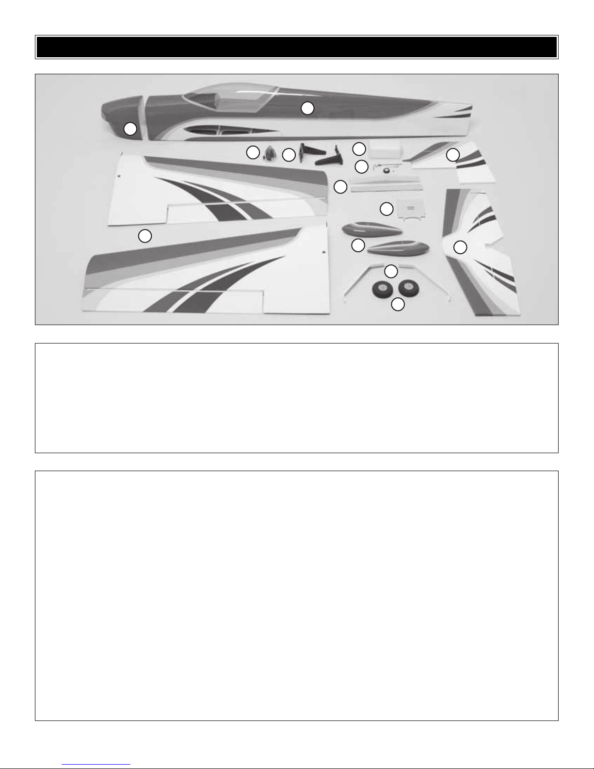
1 Fuselage with canopy and belly
pan [1/4-20 Blind Nuts (2),
8-32 Blind Nuts (4), 3/16" Gray
Pushrod Tubes (4)]
2 Wing Halves (2)
3 Horizontal Stabilizer with Elevators
4 Vertical Stabilizer (Fin) with Rudder
5 Cowl
6 Wheel Pants (2)
7 Fuel Tank with Hardware
8 Tail Gear Wire, Tail Wheel,
Aluminum Tail Gear Mount
9 Aluminum Main Landing Gear
(Right and Left)
10 Spinner Cone, Back Plate Nut,
Bolt, Wrench
11 70 mm Wheels (2)
12 Plywood Receiver/Battery Tray
13 Wing Joiner and Wing Joiner Brace
14 Engine Mount Halves
(Right and Left)
Kit Contents (Photographed)
#8 Lock Washers (12)
#8 Flat Washers (8)
8-32 x 1" SHCS (Socket Head
Cap Screws) (4)
8-32 x 1-1/4" SHCS (4)
8-32 Blind Nuts (8)
#4 x 5/8" Phillips Screws (4)
#4 Lock Washers (4)
#4 Flat Washers (4)
2-56 x 36" [910 mm] Pushrods (4)
Screw-Lock Connector (1)
Nylon Retainer for Screw-Lock (1)
4-40 x 1/8" SHCS (1)
Nylon Ball Link (1)
0-80 Ball Link Ball (1)
0-80 Nut (1)
Aluminum Fuel Line Plug (1)
Heat Shrink Tubing (6)
36" [910 mm] Gray Pushrod Guide
Tubes (5)
#2 x 3/8" Screws (4)
8-32 x 3/4" SHCS (4)
#6 Washers (8)
1/4-20 Blind Nuts (2)
1/4-20 x 2" Nylon Wing Bolts (2)
#2 x 3/8" Button-Head Screws (4)
5-32 x 1-1/4" Axles (2)
5/16"-24 Lock Nuts (2)
5/32" Wheel Collars (4)
6-32 x 1/4" SHCS (4)
2-56 x 3/8" Phillips Screws (4)
2-56 Blind Nuts (4)
#2 Lock Washers (4)
4-40 x 12" Pushrods (3)
Large Solder Clevises (3)
4-40 Metal Clevises (3)
4-40 Nuts (3)
Silicone Clevis Retainers (12)
Giant Control Horns (3)
4-40 x 5/8" Phillips Screws (12)
Mounting Plates for Giant Control
Horns (3)
#4 x 3/8" Phillips Screws (2)
3/32" Wheel Collars (2)
4-40 Set Screw (1)
4-40 x 1/4" SHCS (1)
2-56 Metal Clevises (5)
2-56 Nuts (5)
Small Solder Clevis (4)
2-56 x 6" [150 mm] Pushrods (2)
Large Control Horns (2)
#2 x 1/2" Phillips Screws (4)
Paper Tube (1)
CA Hinge Strips (2)
3/16" x 3/16" x 4" [5 x 5 x 100 mm]
Hardwood Sticks
Plywood Throttle Guide Tube Holders (2)
#64 Rubber Bands (4)
8" [200 mm] Velcro Strips (2)
Pilot
Kit Contents (Not Photographed)
KIT CONTENTS
1
5
2
10
14
13
6
7
8
12
9
11
4
3
Page 8
During construction there will be several occasions where
epoxy cleanup will be necessary. Instead of wasting whole
paper towels, stack three or f our paper to wels on top of each
other and cut them into small squares. This will conserve
paper towels and the little squares are easier to use. For
epoxy clean up dampen the squares with denatured alcohol.
❏ 1. Examine the covering on all parts of the airframe.Where
necessary , use a cov ering iron with a covering sock to remo ve
any wrinkles. Over sheeted areas, first glide the iron over the
wrinkle until it shrinks. Then go back over the area again,
pressing hard on the iron to thoroughly bond the covering to
the wood.Hint: Use a small T-pin to poke several holes in the
covering over the lightening holes on the bottom of the
elevators. This will allow expanding air to escape during the
heating and tightening process.
❏ 2. Use a trim iron to thoroughly seal the covering around
the firewall, around the air passage cutout at the firewall
under the fuselage, and around the formers at the front and
back of the wing saddle.
❏ 3. Use your finger to lightly spread 30-minute epoxy over
the edges of the covering around the firewall—this will
guarantee that the covering is thoroughly sealed and fuelproofed. Use an epoxy brush to lightly coat the formers at
both ends of the wing saddle as well.
PREPARATIONS
8
Page 9
❏ 4. Use epoxy to glue the 1/8" [3 mm] plywood wing joiner
brace to the balsa wing joiner. Use clamps or masking tape
to hold the pieces together while the epoxy hardens.Set the
joiner aside so the assembly will be ready when it’s time to
join the wings later.
Set the fuselage and wing joiner assembly aside while you
work on the wings…
❏❏1.Cut four hinges from the precut CA hinge strip.Stick
a T-pin through the middle of each hinge. Insert the hinges
into the hinge slots in one of the wing halves.
❏❏2.Join the matching aileron to the wing, and then take
out the T-pins. Make sure there is a small gap between the
leading edge of the aileron and the wing—just enough to
see light through or to slip a piece of paper through.
❏❏3. Apply at least eight drops of thin CA to the top and
bottom of each hinge. Allow enough time between drops so
the CA can soak into the hinge rather than running into the
hinge gap.Hint: CA applicator tips are highly recommended.
❏❏4. After the CA has hardened for a few minutes, pull
hard on the aileron to make sure it is secure. Add more CA
if necessary.
❏ 5.Join the other aileron to the other wing half the same way .
❏ 1. Use a straightedge and a hobby knife to cut the
covering 1/8" [3 mm] inside the openings in the bottom of
both wings for the aileron servos.Slit the covering up to the
corners of the openings.
❏ 2. Also cut the covering from the top of the wings over the
holes for the servo wires (next to the root end of both wings) and
from the top and bottom of the wings over the wing bolt holes.
❏ 3. Use a tr im iron to iron the covering down inside the
aileron servo openings.
Mount the Servos and
Hook Up the Ailerons
Hinge the Ailerons
ASSEMBLE THE WING
9
CUT THE COVERING
1/8" [3mm] FROM
THE EDGES OF
THE OPENING.
SLIT THE COVERING
UP TO THE CORNERS.
SERVO OPENING
IN WING.
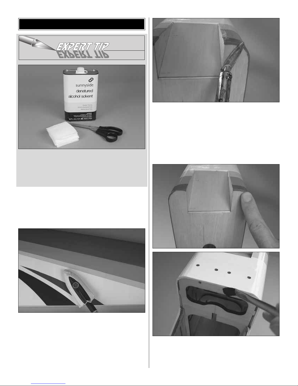
Page 10
❏ 4. Connect a 12" [300 mm] servo extension wire to each
aileron servo. Cut one of the included black heat shrink
tubes in half, making two 1-1/2" [40 mm] pieces.Center the
pieces of tubing over the connections between the servo
wires and the extensions and use a heat gun to shrink the
tubing, making the connections secure.
Refer to this photo while mounting the servos
and hooking up the ailerons.
❏ 5. Use the string in the wings to pull the ser vo wires out
while placing the servos in the openings.With the servos in
position, drill 1/16" [1.6 mm] holes into the wing for all the
servo mounting screws. Temporarily mount the servos with
the servo mounting screws that came with your servos.
❏ 6. Read the Exper t Tip below on how to solder. Then
connect the aileron servos to the ailerons using the
hardware shown in the photo. When mounting the horns,
place the front edge at the front edge of the aileron as
indicated by the arrow in the illustration.Drill 1/16" [1.6 mm]
holes through the ailerons for the screws.If using new, fourarm servo arms, do not cut the extra arms off until instructed
to do so when setting up the radio later.
Note: Set up the ailerons so the servo arms that the
pushrods will be mounted to are opposed.
HOW T O SOLDER
❏ A. Use denatured alcohol or other solvent to thoroughly
clean the pushrod. Roughen the end of the pushrod with
coarse sandpaper where it is to be soldered.
❏ B. Apply a few drops of soldering flux to the end of the
pushrod, and then use a soldering iron or a torch to heat it.
“Tin” the heated area with silver solder (GPMR8070) by
applying the solder to the end. The heat of the pushrod
should melt the solder—not the flame of the torch or
soldering iron—thus allowing the solder to flow. The end of
the wire should be coated with solder all the way around.
❏ C. Place the clevis on the end of the pushrod. Add
another drop of flux, then heat and add solder.The same as
before, the heat of the parts being soldered should melt the
solder, thus allowing it to flo w. Allow the joint to naturally cool
without disturbing. Avoid excess blobs, but make certain the
joint is thoroughly soldered.The solder should be shiny, not
rough. If necessary, reheat the joint and allow to cool.
❏ D. Immediately after the solder has solidified, but while it
is still hot, use a cloth to quickly wipe off the flux before it
hardens. Important: After the joint cools, coat with oil to
prevent rust.Note: Do not use the acid flux that comes with
silver solder for electrical soldering.
This is what a properly soldered clevis looks like—shiny
solder with good flow, no blobs, flux removed.
10
CONNECT THE PUSHRODS TO THE SERVO
ARMS SO THEY ARE OPPOSITE, AS SHOWN.
Page 11

❏ 7. Now that the servos and control horns have been
mounted, remove the servo mounting screws and the
control horn screws. Add a few drops of thin CA to each
screw hole to harden the “threads”in the holes. After the CA
has hardened, reinstall all the screws to securely mount the
servos and the horns.
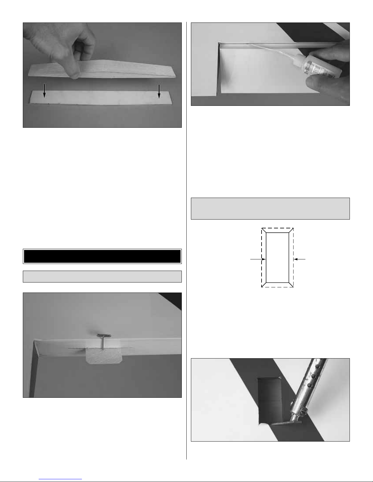
❏ 1.Without using any glue, test fit the wing halves with the
joiner prepared earlier.Make sure the halves fit together well.
If there is a problem with the fit, look for obstructions such as
glue bumps or wood slivers inside the wings where the
joiners fit.Make any adjustments necessary to get a good fit.
❏ 2. Place a sheet of wax paper on your workbench and
gather all the items required for joining the wings, which are
30-minute epoxy, a mixing cup, an epoxy mixing stick, an
epoxy brush, paper towels and denatured alcohol for epoxy
clean up.Caution: Do not use 5-minute epoxy f or joining the
wing halves.It will not provide enough working time.
❏ 3. Separate the wings and take out the joiner. Mix
approximately 3/4 oz. [20cc] of 30-minute epoxy. Pour a
generous amount into the wings where the joiner goes.
Working quickly, use piece of wire or a dowel to distribute
the epoxy all the way around inside the wings.
❏ 4.Use an epoxy brush to coat the root ribs of both wings
and one half of the joiner all the way around. Slowly insert
the epoxy-coated half of the joiner .Wipe away excess epoxy
as it is forced out. Note: There should be no air pockets
inside the wing where the joiner fits—the cavity should be
filled with epoxy. Proceed immediately to the next step.
❏ 5. Coat the protruding end of the joiner all the way around
with epoxy. Join the other wing, slowly pressing the two
halves together , allowing excess epo xy to drip out as you go.
When the wings come together, wipe away excess epoxy
that is squeezed out, then use a C-clamp and several strips
of masking tape on both the top and bottom of the wing to
tightly hold the two halves together. If epoxy continues to
work out of the wing under the tape, remove one strip at a
time and wipe off the epoxy, then replace with another strip
of tape.Do not disturb the wing until the epoxy has hardened.
IMPORTANT! Be cer tain the leading and trailing edges of
both wing halves align with each other where they join.
❏ 6. After the epoxy has hardened, slowly and carefully pull
away the masking tape.If any of the covering loosened, iron
it back down with a covering iron with a covering sock on
medium heat.
Read steps 3 through 5 all the way through before
proceeding.It is important to use the proper technique
for joining the wing halves to ensure a strong wing.
Join the Wing
11
Page 12

❏ 1.Bolt the wing to the fuselage with two 1/4-20 x 2" [50 mm]
nylon wing bolts and the plywood wing bolt plate.
❏ 2. Place the belly pan into position. Use a fine-point felt-
tip pen to mark the outline of the belly pan onto the wing.
❏ 3. Use the method in the Expert Tip that follows, or a
sharp hobby knife, to carefully cut the covering from the
bottom of the wing 1/16" [2 mm] inside the lines you marked.
Caution: Using the soldering iron technique to cut the
covering as shown in the Expert Tip is recommended, but if
you have to use a hobby knife be certain to use a sharp
blade so it will easily cut the covering without having to apply
too much pressure.Be certain not to cut into the wood or the
wing will be weakened.
HOW TO CUT COVERING FROM BALSA.
To avoid cutting into the balsa, use a soldering iron instead
of a hobby knife to cut the covering.The tip of the soldering
iron doesn’t have to be sharp, but a fine tip does work best.
Allow the iron to heat fully. Use a straightedge to guide the
soldering iron at a rate that will just melt the covering and not
burn into the wood. The hotter the soldering iron, the faster
it must travel to melt a fine cut.
❏ 4. Peel off the covering from the bottom of the wing.Use
one of your paper towel squares dampened with denatured
alcohol to remove any ink.
❏ 5.Bolt the wing back onto the fuselage with the wing bolt
plate. Only this time, use epoxy or thick CA to glue the wing
bolt plate to the bottom of the wing—be careful not to get
any glue on the wing bolts.
Add the Belly Pan
ASSEMBLE THE FUSELAGE
12
Page 13

❏ 6. Use a single-edge razor blade or a hobby knife to cut
off any covering wrapped around the edges of the belly pan.
Also cut the covering from the holes in the bottom of the
belly pan where the wing bolts go through.
❏ 7.Cut two 2" [50 mm] pieces from the 1/2" x 8" [13 x 200 mm]
paper tube.Glue the plywood tube retainer rings to the bottom
of the paper tubes.Then, insert the tubes up through the holes
in the belly pan, but do not glue them in.
❏ 8. Position the belly pan assembly on the wing. Make
sure the paper tubes are fit over the heads of the wing bolts,
and then press down on the paper tubes. Use a fine-point
ballpoint pen to mark the bottom of the belly pan all the way
around both paper tubes.
❏ 9.Remove the assembly and take out the paper tubes .Then
cut them off along the bottom edge of the lines you marked.
❏ 10. Reinsert the paper tubes into the belly pan and
reposition the assembly on the wing. Position the tubes as
necessary so the ends will be flush with the bottom of the
belly pan. Make adjustments and trim where necessary.
Remove the assembly and use medium CA or epoxy to glue
the tubes to the belly pan from the inside.
❏ 11. With the wing bolted to the fuselage and the model
supported upside-down, use 30-minute epoxy mixed with
microballoons to glue the belly pan and the paper tubes to
the bottom of the wing—be careful not to inadvertently glue
the assembly to the fuselage.Place weights on the belly pan
to hold it down, wipe away excess epoxy and do not disturb
until the epoxy has hardened.
❏ 1. Cut the covering from both sides of the fuselage over
the slots for the stabilizer. (The cutouts can be seen in
following photos.)
IF MOUNTING THE SERVOS OUTSIDE
THE FUSELAGE, GO TO STEP 3.
❏ 2. If mounting the servos inside the fuselage, cut the
covering from the pushrod exits.
Join the Stabilizer and Fin
13
Page 14

❏ 3.If mounting the servos
outside
the fuselage, the same as
was done for the aileron servos, cut the covering 1/8" [3 mm]
from the edges of the servo openings in the fuselage and iron
the covering down inside.Temporarily mount the servos, drill
1/16" [1.6 mm] holes for the screws, install the scre ws, remov e,
and then harden the screw holes with thin CA.Do not reinstall
the servos at this time.
❏ 4. Temporarily slide the stabilizer into position in the
fuselage. With the wing mounted, stand approximately ten
feet [3 meters] behind the model and see if the stab aligns
horizontally with the wing.If they do align go to the next step.
If the stab and wing do not align, first try placing a few ounces
of weight on the high side of the stab. If that doesn’t do it,
remove the stab from the fuselage and lightly sand the slots
in the fuselage to get the stab to align with the wing.Reinsert
the stab and check the alignment. If necessar y, continue to
make small adjustments until alignment is achieved.
❏ 5. Remove the stabilizer from the fuselage. Taking
accurate measurements, use a fine-point felt-tip pen to mark
the middle of the stabilizer on the trailing edge. Again with
accuracy, mar k two more lines 7/16" [11 mm] on both sides
of the centerline. Replace the stabilizer in the fuselage.
❏ 6.Using the lines you marked as an alignment cue, center
the trailing edge of the stabilizer in the fuselage.Stick a T-pin
through both sides of the trailing edge at the fuselage—this
will temporarily lock the stab into place allowing the leading
edge to pivot.
❏ 7. Stick another T-pin into the bottom of the fuselage
centered between the holes for the main landing gear bolts.
Tie a loop in an approximately 60" [150cm] piece of nonelastic string. Slip the loop in the string over this T-pin.
14
Page 15

❏ 8. Fold a piece of masking tape over the string near the
other end and draw an arrow on it. Slide the tape along the
string and align the arrow with one end of the stab as shown.
Swing the string over to the same position on the other end
of the stab.Rotate the stab about the trailing edge and slide
the tape along the string until the stab is centered and the
arrow aligns with both ends, as shown in the sketch.
❏ 9. Use a fine-point felt-tip pen to mark the outline of the
fuselage on the top and bottom of both sides of the stab.
❏ 10.The same as was done when mounting the belly pan
to the bottom of the wing, use a heated soldering iron to cut
the covering 1/16" [2 mm] inside the lines you marked, then
peel the covering from the stab.
❏ 11.When gluing two parts together, one of the things that
can be done to achieve the strongest bond possible is to
apply glue to both parts being joined (as was done when
joining the wing halves). And like the wing, this is impor tant
when gluing in the stabilizer—epoxy should be applied
liberally in the stab slot in the fuselage and to the stab. But
to keep the stab clean while sliding it in, wrap one half with
a thin plastic bag or food wrap.
Finally! Time to glue in the stab…
❏ 12. Thoroughly coat all joining areas of the stabilizer
and fuselage with 30-minute epoxy. Then immediately slide
the stab into position. Use more paper towel squares and
denatured alcohol to wipe off excess epoxy. Take off any
protective wrapping around the stab and continue to clean
off epoxy. Reinsert the T-pins through the back of the stab on
both sides of the fuselage and use the pin-and-string to
permanently center the stab. Position any weight used to
align the stab with the wing. Do not disturb the model until
the epoxy has hardened.
❏ 13.The same as was done for the stabilizer, slide the fin
into position, mark the outline of the fuselage on both sides,
cut and peel off the covering, then use 30-minute epoxy to
glue the fin into position.
❏ 14. After all the epoxy has hardened, join the elev ators to
the stab with the CA hinges and thin CA. Don’t forget to use
T-pins to keep the hinges centered.
A = A'
15
A
A'
Page 16

Before joining the rudder to the fin, the tail gear has to
be put together…
❏ 15. Slide a 3/32" [2.4 mm] wheel collar onto the tail gear
wire and tighten it down with a drop of threadlocker and a
4-40 x 1/4" [6.4 mm] SHCS (socket-head cap screw).Install
the tail gear mount as shown, and then use pliers to bend the
wire.Viewed from above, the bend should be 90-degrees to
the axle part of the wire where the wheel goes. If the bend
has to be adjusted, hold the wire with pliers at the coil and
bend the wire as necessary to achieve the 90-degree angle.
Refer to this photo for the next two steps.
❏ 16. Temporarily join the rudder to the fin and fuselage
with three hinges. Lay the tail gear wire on the fuselage as
shown. Make sure the “torque rod” part of the wire is
perpendicular to the leading edge of the rudder. Bend the
wire as necessary.
❏ 17. Use a fine-point felt-tip pen to mark the rudder on
both sides of the wire.
❏ 18. Set the tail gear wire aside and take out the rudder.
Using the marks on the rudder for alignment, drill a 3/32"
[2.4 mm] hole into the rudder for the torque rod part of the
wire.Use a 3/32" [2.4 mm] brass tube sharpened on the end
or a hobby knife to cut a groove in the leading edge of the
rudder to accommodate the tail gear wire.
❏ 19. Use epoxy to glue the tail gear wire into the rudder.
Then before the epoxy hardens , join the rudder to the fin and
fuselage with the hinges. Permanently glue in the hinges
with thin CA. Mount the tail gear bracket by drilling two
3/32" [2.4 mm] holes for two #4 x 3/8" [9.5 mm] screws.
Temporarily mount the bracket with the screws, remove the
screws and harden the holes with thin CA. After the holes
have hardened, mount the bracket.
16
Page 17

EXTERNALLY MOUNTED SERVOS
❏ 1. Connect 24" [610 mm] servo extensions to the rudder
servo and both elevator servos.Secure the connections with
the heat shrink tubing provided with this kit.
❏ 2. Guide the servo wires through the fuselage up into the
radio compartment and mount the servos using the screws
that came with them (the holes should have been pre viously
drilled and hardened).
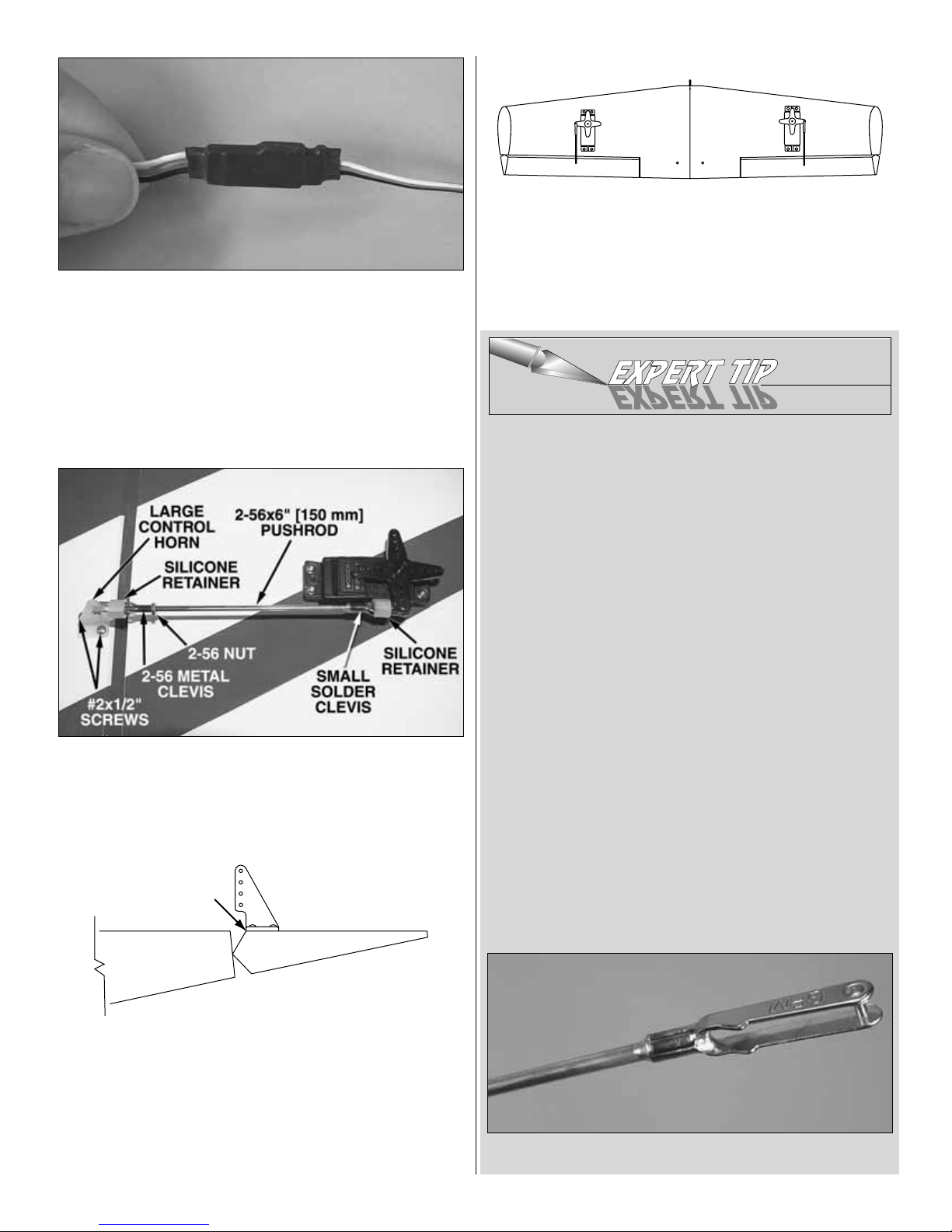
❏ 3. Make the pushrods and connect the servos to the
control surfaces using the hardware shown in the photos.
When mounting the horns, locate the pushrod holes over the
pivot point and use 4-40 x 5/8" [16 mm] Phillips screws and
the mounting plates to mount the horns. Drill 1/8" [3.2 mm]
holes through the rodder for the screws. Note: Trim the
rudder horn as shown so it will not interfere with the fuselage.
INTERNALLY MOUNTED SERVOS
❏ 1. Make three identical pushrod assemblies like the one
shown in the photo.(Turn the clevises approximately fifteen
full turns onto the pushrods.)
❏ 2. Guide the pushrods through the guide tubes in the
back of the fuselage and mount the horns with 4-40 x 5/8"
[16 mm] Phillips screws and the back plates on the other
side. Use a 1/8" [3.2 mm] dr ill for the screws.
Mount the Servos and
Hook Up the Controls
17
ALIGN THE PUSHROD
HOLES WITH THE PIVOT
TRIM HERE
(FOR RUDDER ONLY)
MOUNTING PLATE
Page 18

Refer to this photo while mounting the servos
and hooking up the pushrods.
❏ 3. Place the elevator and rudder servos in the servo tray,
but do not screw them in yet. Bend and cut one of the
elevator pushrods to join up with the other elevator pushrod
as shown.With both elevators centered, connect the elevator
pushrods with two 5/32" [4 mm] wheel collars and 6-32 x 1/4"
[6 mm] SHCS and a few drops of threadlocker on the
threads. Note: Do not cut off the unused servo arms until
setting up the radio later.
❏ 4. Cut the pushrods to the correct length, and then solder
a small, metal clevis onto the end of each pushrod.(This will
be easier to do if the pushrods are disconnected from the
control horns on the elevators and rudder.)
❏ 5. Reconnect the pushrods to the control horns and
connect them to the servo arms. Mount the servos in the
servo trays by drilling 1/16" [1.6 mm] holes for the screws
and using the screws that came with the servos. Remove
the screws, harden the holes with thin CA, allow to harden,
and then mount the servos again with the screws.
Refer to this sketch while mounting the wheels.
❏ 1. Use a 1/2" and a 7/16" wrench to bolt both axles to
both main landing gears. Use a reinforced cutoff wheel or
metal file to file an approximately 3/16" [5 mm] long flat spot
approximately 1/8" [3 mm] from the end of both axles.
❏ 2. With #6 washers to center the wheel in the pant, use
two 2-56 x 3/8" [10 mm] screws and #2 lock washers to
mount the pants to the landing gear with the wheel and a
5/32" [4 mm] wheel collar.Secure the collar to the axle with
a 6-32 x 1/4" [6 mm] SHCS (socket-head cap screw) and a
drop of threadlocker on the threads.
❏ 3. Mount the landing gear to the bottom of the fuselage
with four 8-32 x 3/4" [19 mm] SHCS, #4 loc k washers and #4
flat washers.
Mount the Main Landing Gear
18
5/32" [4 mm]
WHEEL COLLAR
#6 WASHERS
AS SPACERS
AND 6-32 SHCS
5/32" WHEEL COLLARS
WITH 6-32 SHCS
1
2
4
3
Bend and cut one pushrod to join with
the other. Secure with wheel collars.
Page 19

❏ 1. Determine which Engine Mounting Template from the
back of the manual you will use.
Angled
templates are
provided for the O.S. 1.20 Surpass and the O.S. .91FX.
Mounting the engine at an angle will locate the exhaust in the
exhaust cut out on the bottom of the fuselage—partially
avoiding the deposit of oily exhaust residue all over the
model.If standard side or inverted mounting is preferred, use
the regular template.
❏ 2. Cut out whichever template you have decided to use.
Temporarily attach the template to the firewall with tape or
repositionable spray adhesiv e so the lines on the template align
with the cross marks on the firewall. Use a large T-pin or a
sharpened piece of wire to transfer the cross marks in the
template to the firewall.Before drilling the holes in Step 3, check
that the engine and muffler you will be using will fit on the plane.
❏ 3. Remove the template. Then drill 1/16" [1.6 mm] pilot
holes through the firewall at the marks. Enlarge the holes
with a 13/64" [5.2 mm] or 3/16" [4.8 mm] drill.Put a few dabs
of epoxy on the front of four 8-32 blind nuts where they will
go into the firewall.Use an 8-32 x 1" [25 mm] SHCS with two
or three #8 washers to draw the blind nuts into the back of
the firewall.Wipe away any excess epoxy.
❏ 4. Mount the engine mount to the firewall with four
8-32 x 1-1/4" [32 mm] SHCS, four #4 lock washers and four
#4 flat washers, but do not tighten the screws yet.
❏ 5. Place your engine on the mount, adjust the mount to
fit your engine, and tighten the screws. Position the engine
on the mount so the back plate of the spinner will be 6-1/4"
[160 mm] from the firewall. Use small C-clamps or just hold
the engine down while marking the engine mounting bolt
holes in the mount—a Great Planes Dead Center™Engine
Mount Hole Locator (GPMR8130) works the best.
❏ 6.Remove the engine from the mount.If you have access
to a drill press, remove the mount from the firewall and drill
#29 holes at the marks you made. If you don’t have a drill
press, just drill the holes in the mount while it is on the
firewall. Use an 8-32 tap to tap threads in the holes. Mount
the engine to the mount with four 8-32 x 1" [25 mm] SHCS
and #4 lock washers.
Mount the Engine
19
Page 20

These are the cutting bits recommended
for cutting the holes in the cowl.
❏ 1. Estimate the size, shape and location of the engine
cutout in the cowl. Use a fine-point felt-tip marker to draw a
rough shape of the cutout directly on the cowl.Use a carbide
cutter or similar high-speed rotary cutting tool to cut the
hole—start by making the hole small.Test fit the cowl to the
fuselage and enlarge the hole where necessary to get it to
fit. Use the backplate of the spinner to accurately position
the cowl so you will know where the cutout should be.
Hint: Until you have finalized the size and shape of the
engine cutout, it may be easier to remove and install the
cowl if the valve cover (for four-strokes) or engine head (for
two-strokes) is temporarily removed.
❏ 2. With the cowl in position, use a fine-point felt-tip pen to
mark both sides of the aft edge of the cowl onto the
fuselage. Also mark four locations for the cowl mounting
screws on both the cowl and the fuselage.Remove the cowl.
❏ 3. Using the lines on the sides of the fuselage as a
reference, drill 3/32" [2.4 mm] holes in the cowl at the four
marks so that the holes will be 3/16" [5 mm] aft of the
firewall—this will center the screws in the edges of the fire wall.
❏ 4. Reposition the cowl onto the fuselage and “center it
up” using the backplate of the spinner. Using tape or an
assistant to hold the cowl in position, drill 3/32" [2.4 mm]
holes through the holes you already drilled in the cowl into
the sides of the firewall.
Mount the Cowl
20
Page 21

❏ 5. Remove the cowl. Enlarge the holes in the cowl only
with a 1/8" [3.2 mm] drill. Then, mount the cowl to the
fuselage with four #4 x 5/8" [16 mm] screws, #4 lock
washers and #4 flat washers. As you have been doing all
along, remove the screws , harden the holes with a fe w drops
of thin CA and allow to harden.
Now is a good time to install the fuel tank…
❏ 6. While we’ve got the cowl off, assemble the fuel tank.
Cut the aluminum tubes and the fuel lines that go into the
tank to the correct length and fit them into the stopper as
shown—later, you can refer to the sketch so you will know
how to connect the lines outside the tank. Also write “TOP”
on the back of the tank near one edge so you will know how
to install the stopper and mount the tank into the fuselage.
An optional, second clunk is provided should you decide to
use a third line for fueling/defueling. Outside the tank this
line will have to be closed off during flight with the included
aluminum fuel line plug. When the tank is assembled, be
certain the clunk on the fuel lines inside cannot contact the
back of the tank—otherwise they may become stuck.
❏ 7.Hook a rubber band or two around the plywood tabs in
the fuel tank former, then stretch the rubber bands tow ard the
top of the fuselage and slide the tank into position.The neck
of the tank should protrude through the hole in the firewall.
❏ 8.Cut any other holes necessary in the cowl for the glow
plug igniter, muffler, needle valve, low-end needle, etc.
❏ 1.Use a wire sharpened on the end or something similar
to mark the firewall where the throttle pushrod should
protrude to align with the carburetor arm.
❏ 2. If necessary, remove the engine.Then, using care not
to drill into the fuel tank, drill a 3/16" [4.8 mm] hole through
the firewall.
❏ 3. Re-mount the engine, and then hook up the throttle
using the hardware shown.Fit, but do not glue the plywood
guide tube holders into position where shown.
Hook Up the Throttle
VENT/PRESSURE
FUELING/DEFUELING
(OPTIONAL)
FRONT VIEW
PICKUP TO CARB
21
Page 22

❏ 1. Glue both 3/16" x 3/16" x 4" [5 x 5 x 100 mm] hardwood
receiver/battery tray mounts into position where shown—
be certain the forward throttle guide tube holder will not
interfere with the plywood receiver/battery tray.
❏ 2. Position the plywood receiver battery tray on the tray
mounts you just glued in. Dr ill 1/16" [1.6 mm] holes through
the tray and the rails.Remove the tray, enlarge the holes in
the tray only with a 3/32" [2.4 mm] drill, and then mount the
tray to the rails with four #2 x 3/8" [10 mm] screws.Remove
the screws and the tray, harden the screw holes with thin
CA, allow to harden, then mount the tray.
❏ 3. Now you may glue the guide tube holders into position.
Refer to the following photo while
completing the radio installation.
❏ 4. Mount the receiver and battery pack to the forward or
aft radio trays with 1/4" [6 mm] R/C foam (not included) and
the V elcro strips.
❏ 5. Mount the on/off switch in a location that will be easy
to reach from outside the model and will not get coated with
engine exhaust.
❏ 6. Guide the receiver antenna through the antenna tube
down the fuselage.
❏ 1.Trim the base of the pilot so he will fit under the canopy
when both are in poistion on the fuselage.The same as was
done for the cov ering over the stabiliz er and belly pan, mark,
then cut and remove the covering from the cockpit floor for
the pilot. Securely glue the pilot into position with CA.
❏ 2.Drill 3/32" [2.4 mm] holes through the canopy at the four
locations shown.
❏ 3.Place the canopy on the fuselage.Using the holes in the
canopy as a guide, drill 1/16" [1.6 mm] holes into the fuselage.
Mount the Pilot and Canopy
Finish Radio Installation
FINAL ASSEMBLY
22
Page 23

❏ 4. Mount the canopy to the fuselage with four #2 x 3/8"
[9.5 mm] button-head screws. Remove the screws and
canopy, harden the holes with thin CA, allow to harden, and
then mount the canopy.
1.Use scissors or a sharp hobby knife to cut the decals from
the sheet.
2. Be certain the model is clean and free from oily
fingerprints and dust. Prepare a dishpan or small bucket with
a mixture of liquid dish soap and warm water—about one
teaspoon of soap per gallon of water.Submerse the decal in
the soap and water and peel off the paper backing. Note:
Even though the decals hav e a “sticky-back”and are not the
water transfer type , submersing them in soap & water allo ws
accurate positioning and reduces air bubbles underneath.
3. Position decal on the model where desired. Holding the
decal down, use a paper towel to wipe most of the water a way.
4. Use a piece of soft balsa or something similar to
squeegee remaining water from under the decal. Apply the
rest of the decals the same way.
❏ 1. With the radio system connected and operating, turn
on the transmitter and receiver.
❏ 2. Make certain that the control surfaces and the carburetor
respond in the correct direction. If necessary, use the servo
reversing to reverse any servos that are going the wrong way.
❏ 3. Center all the trims on the transmitter.Starting with the
rudder servo and with the radio on, test-fit the four-arm
servo arm in one of the four positions until you find the one
that is 90-degrees. Cut off the remaining ar ms. Repeat for
the rest of the servos.
90°
NO NO NO
YES
90-DEGREES!
NOTE THE NUMBERS ON EACH ARM.
ROTATE THE ARM UNTIL YOU FIND ONE
THAT IS 90˚, THEN CUT OFF THE OTHERS.
2
3
4
1
2
Check the Control Directions
and Center the Servos
GET THE MODEL READY TO FLY
Apply the Decals
23
4-CHANNEL RADIO SETUP
(STANDARD MODE 2)
4-CHANNEL
TRANSMITTER
ELEVATOR MOVES UP
4-CHANNEL
TRANSMITTER
RIGHT AILERON MOVES UP
LEFT AILERON MOVES DOWN
RUDDER MOVES RIGHT
CARBURETOR WIDE OPEN
4-CHANNEL
TRANSMITTER
4-CHANNEL
TRANSMITTER
Page 24

Use a Great Planes AccuThrow (or a ruler) to accurately
measure and set the control throw of each control surface as
indicated in the chart that follows.If your radio does not hav e
dual rates, use the low rate settings.
At this stage the model should be in ready-to-fly condition
with all of the systems in place including the engine, cowl,
propeller, spinner and all components of the radio system.
❏ 1. If you will be using a Great Planes C.G. Machine to
balance the model, mount the wing to the fuselage and
proceed to the next step. If you will not be using a C.G.
Machine, use a fine-point felt-tip pen to accurately mark the
C.G. on the top of the wing 6-1/2" [165 mm] back from the
flat part of leading edge at the middle. Lay a piece of narrow
(1/8" [2 mm]) tape over the line so you will be able to feel it
with your fingers when lifting the model to check the C.G.
❏ 2.With the wing attached to the fuselage, all parts of the
model installed (ready to fly) and an empty fuel tank, place
the model upside-down on the CG Machine or lift it upsidedown at the balance point you marked.
This is where your model should balance for the first flights.
Later, y ou ma y wish to e xperiment by shifting the C .G.up to
1/2" [13 mm] forward or 1/2" [13 mm] back to change the
flying characteristics.Moving the C.G.forward may impro ve
the smoothness and stability , b ut the model will then be less
aerobatic and may require more speed for takeoff and
make it more difficult to slow for landing.Moving the C.G.aft
makes the model more maneuverab le, but could also cause
it to become too difficult to control.In any case, start at the
recommended balance point and do not at any time
balance the model outside the specified range.
More than any other factor, the C.G. (balance point) can
have the greatest effect on how a model flies, and may
determine whether or not your first flight will be
successful. If you value this model and wish to enjoy it for
many flights, DO NOT OVERLOOK THIS IMPORTANT
PROCEDURE. A model that is not proper ly balanced will
be unstable and possibly unflyable.
Balance the Model (C.G.)
IMPORTANT: The Venus II ARF has been extensively
flown and tested to arrive at the throws at which it flies
best. Flying your model at these throws will provide you
with the greatest chance for successful first flights.If, after
you have become accustomed to the way the Venus II
ARF flies, you would like to change the throws to suit your
taste, that is fine. However, too much control throw could
make the model difficult to control, so remember, “more is
not always better.”
These are the recommended control surface throws:
High Rate Low Rate
ELEVATOR: 9/16" [14 mm] up 3/8" [10 mm] up
9/16" [14 mm] down 3/8" [10 mm] down
RUDDER: 3" [76 mm] right 1-3/4" [44 mm] right
3" [76 mm] left 1-3/4" [44 mm] left
AILERONS: 7/8" [22 mm] up 1/2" [13 mm] up
7/8" [22 mm] down 1/2" [13 mm] down
NOTE:The throws are measured at the widest part of the
elevators, rudder and ailerons.
Set the Control Throws
24
Page 25

❏ 3. If the tail drops, the model is “tail heavy” and weight
must be added to the nose to balance.If the nose drops, the
model is “nose heavy” and weight must be added to the tail
to balance. If possible, relocate the battery pack and
receiver to minimize or eliminate any additional ballast
required. If additional weight is still required and you are
using a glow engine, nose weight may be easily added by
using a “spinner weight” (GPMQ4645 for the 1 oz. [28g]
weight, or GPMQ4646 for the 2 oz. [57g] weight). If spinner
weight cannot be used or is not enough, use Great Planes
(GPMQ4485) “stick-on”lead.To find out how much weight is
needed, begin by placing incrementally increasing amounts
of weight on the fuselage where needed until the model
balances. Once you have determined the amount of weight
required, it can be permanently attached. A good place to
add stick-on nose weight is to the firewall or inside the fuel
tank compartment as close to the firewall as possible.
Note: If attaching weight to the firewall, do not rely upon the
adhesive on the back of the lead weight to permanently hold
it in place. Over time, fuel and exhaust residue may soften
the adhesive and cause the weight to fall off. Use #2 sheet
metal screws, RTV silicone or epo xy to permanently hold the
weight in place.
❏ 4. IMPORTANT: If you found it necessary to add any
weight, recheck the C.G.after the weight has been installed.
❏ 1. Turn the model upright and set it on your workbench.
With the wing level, ha ve an assistant help you lift the model
by the engine propeller shaft and the bottom of the fuselage
under the trailing edge of the fin. Do this several times.
❏ 2. If one wing always drops when you lift the model, it
means that side is heavy. Balance the airplane by adding
weight to the other wing tip—it may be stuck directly to the
covering or permanently glued inside the wing. An airplane
that has been laterally balanced will track better in
loops and other maneuvers.
No matter if you fly at an AMA sanctioned R/C club site or if you
fly somewhere on your own, you should always have your
name, address, telephone number and AMA number on or
inside your model.It is required at all AMA R/C club flying sites
and AMA sanctioned flying events. Fill out the identification tag
on page 29 and place it on or inside your model.
Follow the battery charging instructions that came with your
radio control system to charge the batteries. You should
always charge your transmitter and receiver batteries the
night before you go flying, and at other times as
recommended by the radio manufacturer.
Carefully balance your propeller and spare propellers before
you fly. An unbalanced prop can be the single most
significant cause of vibration that can damage your model.
Not only will engine mounting screws and bolts loosen,
possibly with disastrous effect, but vibration may also
damage your radio receiver and battery. Vibration can also
cause your fuel to foam, which will, in turn, cause your
engine to run hot or quit.
We use a Top Flite Precision Magnetic Prop Balancer
™
(TOPQ5700) in the workshop and keep a Great Planes
Fingertip Prop Balancer (GPMQ5000) in our flight box.
If the engine is new, follow the engine manufacturer’s
instructions to break-in the engine. After break-in, confirm
that the engine idles reliably, transitions smoothly and rapidly to
full power and maintains full power—indefinitely. After you run
the engine on the model, inspect the model closely to make
sure all screws remained tight, the hinges are secure, the prop
is secure and all pushrods and connectors are secure.
Ground Check
Balance Propellers
CAUTION: Unless the instructions that came with your
radio system state differently, the initial charge on new
transmitter and receiver batteries should be done for 15
hours using the slow-charger that came with the radio
system.This will “condition” the batteries so that the next
charge may be done using the fast-charger of y our choice.
If the initial charge is done with a fast-charger the
batteries may not reach their full capacity and you may be
flying with batteries that are only partially charged.
Charge the Batteries
Identify Y our Model
PREFLIGHT
Balance the Model Laterally
25
Page 26

Ground check the operational range of your radio before the
first flight of the day. With the transmitter antenna collapsed
and the receiver and transmitter on, you should be able to
walk at least 100 feet [30m] away from the model and still
have control. Have an assistant stand by your model and,
while you work the controls, tell you what the control surf aces
are doing. Repeat this test with the engine running at
various speeds with an assistant holding the model, using
hand signals to show you what is happening. If the control
surfaces do not respond correctly, do not fly! Find and
correct the problem first.Look for loose servo connections or
broken wires, corroded wires on old servo connectors, poor
solder joints in your battery pack or a defective cell, or a
damaged receiver crystal from a previous crash.
• Keep all engine fuel in a safe place, away from high heat,
sparks or flames, as fuel is very flammable. Do not smoke
near the engine or fuel; and remember that engine exhaust
gives off a great deal of deadly carbon monoxide .Therefore
do not run the engine in a closed room or garage.
• Get help from an experienced pilot when learning to
operate engines.
• Use safety glasses when star ting or running engines.
• Do not r un the engine in an area of loose gravel or sand;
the propeller may throw such material in your face or eyes.
• Keep your face and body as well as all spectators away
from the plane of rotation of the propeller as you start and
run the engine.
• Keep these items away from the prop:loose clothing, shir t
sleeves, ties, scarfs, long hair or loose objects such as
pencils or screwdrivers that may fall out of shirt or jacket
pockets into the prop.
• Use a “chicken stick” or electric starter to star t the engine.
Do not use your fingers to flip the propeller. Make cer tain
the glow plug clip or connector is secure so that it will not
pop off or otherwise get into the running propeller.
• Make all engine adjustments from behind the
rotating propeller.
• The engine gets hot! Do not touch it during or right after
operation. Make sure fuel lines are in good condition so
fuel will not leak onto a hot engine, causing a fire.
• To stop a glow engine, cut off the fuel supply by closing off
the fuel line or following the engine manufacturer’s
recommendations. Do not use hands, fingers or any other
body part to try to stop the engine. To stop a gasoline
powered engine an on/off switch should be connected to
the engine coil. Do not throw anything into the propeller of
a running engine.
Read and abide by the following excerpts from the Academy
of Model Aeronautics Safety Code.For the complete Safety
Code refer to
Model Aviation
magazine, the AMA web site or
the Code that came with your AMA license.
1) I will not fly my model aircraft in sanctioned events, air
shows, or model flying demonstrations until it has been
proven to be airworthy by having been previously,
successfully flight tested.
2) I will not fly my model aircraft higher than approximately
400 feet within 3 miles of an airport without notifying the
airpor t operator. I will give right-of-way and avoid flying in
the proximity of full-scale aircraft. Where necessary, an
observer shall be utilized to supervise flying to avoid
having models fly in the proximity of full-scale aircraft.
3) Where established, I will abide by the safety rules for the
flying site I use, and I will not willfully and deliberately fly my
models in a careless, reckless and/or dangerous manner.
5) I will not fly my model unless it is identified with my name
and address or AMA number, on or in the model. Note:
This does not apply to models while being flown indoors.
7) I will not operate models with pyrotechnics (any device
that explodes, burns, or propels a projectile of any kind).
1) I will have completed a successful radio equipment ground
check before the first flight of a new or repaired model.
2) I will not fly my model aircraft in the presence of
spectators until I become a qualified flier, unless assisted
by an experienced helper.
3) At all flying sites a straight or curved line(s) must be
established in front of which all flying takes place with the
other side for spectators. Only personnel involved with
flying the aircraft are allowed at or in the front of the flight
line. Intentional flying behind the flight line is prohibited.
Radio Control
General
AMA SAFETY CODE (
EXCERPTS
)
Failure to follow these safety precautions may result
in severe injury to yourself and others.
ENGINE SAFETY PRECAUTIONS
Range Check
26
Page 27

4) I will operate my model using only radio control
frequencies currently allowed by the Federal
Communications Commission.
5) I will not knowingly operate my model within three
miles of any pre-existing flying site except in
accordance with the frequency sharing agreement
listed [in the complete AMA Safety Code].
9) Under no circumstances may a pilot or other person
touch a powered model in flight; nor should any part of
the model other than the landing gear, intentionally
touch the ground, except while landing.
❏ 1. Fuelproof all areas exposed to fuel or exhaust
residue such as the wing saddle area, the wing
mounting tabs, etc.
❏ 2. Check the C.G. according to the measurements
provided in the manual.
❏ 3. Be certain the battery and receiver are securely
mounted. Simply stuffing them into place with foam
rubber is not sufficient.
❏ 4. Extend your receiver antenna into the antenna tube
inside the fuselage.
❏ 5. Balance your model
laterally
as explained in
the instructions.
❏ 6. Use threadlocking compound to secure critical
fasteners such as the set screws on the wheel
collars, screws that hold the carburetor arm (if
applicable), screw-lock pushrod connectors, etc.
❏ 7. Add a drop of oil to the axles so the wheels will
turn freely.
❏ 8. Make sure all hinges are securely glued in place.
❏ 9. Reinforce holes for wood screws with thin CA where
appropriate (servo mounting screws, cowl mounting
screws, etc.).
❏ 10. Confirm that all controls operate in the correct direction
and the throws are set up according to the manual.
❏ 11. Make sure there are silicone retainers on all the
clevises and that all servo arms are secured to the
servos with the screws included with your radio.
❏ 12. Secure connections between servo wires and Y-
connectors or servo extensions, and the connection
between your battery pack and the on/off switch with
vinyl tape, heat shrink tubing or special clips suitable
for that purpose.
❏ 13. Make sure the fuel lines are connected and are
not kinked.
❏ 14. Balance your propeller (and spare propellers).
❏ 15. Tighten the propeller nut and spinner.
❏ 16.Place your name, address, AMA number and
telephone number on or inside your model.
❏ 17. Cycle your receiver battery pack (if necessary) and
make sure it is fully charged.
❏ 18. If you wish to photograph your model, do so before
your first flight.
❏ 19. Range check your radio when you get to the flying field.
The Venus II ARF is a great-flying model that flies smoothly
and predictably. It does not, however, possess the selfrecovery characteristics of a primary R/C trainer and should
be flown only by experienced R/C pilots.
A fully-cowled engine may run at a higher temperature than
an un-cowled engine. For this reason, the fuel mixture
should be richened so the engine runs at about 200 rpm
below peak speed. By running the engine slightly r ich, you
will help prevent dead-stic k landings caused by overheating.
CAUTION (THIS APPLIES TO ALL
R/C AIRPLANES): If,
while flying, you notice an alarming or unusual sound
such as a low-pitched “buzz,” this may indicate control
surface
flutter.
Flutter occurs when a control surface (such
as an aileron or elevator) or a flying surface (such as a
wing or stab) rapidly vibrates up and down (thus causing
the noise). In extreme cases, if not detected immediately,
flutter can actually cause the control surface to detach or
the flying surface to fail, thus causing loss of control
followed by an impending crash. The best thing to do
when flutter is detected is to slow the model immediately
by reducing power, then land as soon as safely possible.
Identify which surface fluttered (so the problem may be
resolved) by checking all the servo grommets for
deterioration or signs of vibration. Make certain all
pushrod linkages are secure and free of play. If it fluttered
once, under similar circumstances it will probably flutter
again unless the problem is fixed.Some things which can
cause flutter are; Excessive hinge gap; Not mounting
control horns solidly; Poor fit of clevis pin in horn; Sideplay of wire pushrods caused by large bends; Excessive
free play in servo gears; Insecure servo mounting; and
one of the most prevalent causes of flutter;Flying an overpowered model at excessive speeds.
Fuel Mixture Adjustments
FLYING
During the last few moments of preparation your mind may
be elsewhere anticipating the excitement of the first flight.
Because of this, you may be more likely to overlook certain
checks and procedures that should be performed before the
model is flown.To help avoid this, a check list is provided to
make sure these important areas are not overlooked. Many
are covered in the instruction manual, so where appropriate,
refer to the manual for complete instructions. Be sure to
check the items off as they are completed.
CHECKLIST
27
Page 28

Before takeoff , see ho w the model handles on the ground b y
doing a few practice runs at low speeds on the runway. Hold
“up” elevator to keep the tail wheel on the ground. If
necessary , adjust the tail wheel so the model will roll straight
down the runway. If you need to relax before the maiden
flight, turn the engine off and bring the model back into the
pits. Top off the fuel, then check all fasteners and control
linkages for peace of mind.
The Venus II is a stable, honest flier (as any pattern-type
plane should be). Takeoff is straightforward—just remember
to hold a bit of down elevator until she gets up-to-speed to
keep the tail on the ground. Get ready to apply a little right
rudder when the model rotates and lifts into the air.
Otherwise, be smooth on the controls and make a gentle
climbout to a safe altitude before making the first turn.
For reassurance and to keep an eye on other traffic, it is a
good idea to have an assistant on the flight line with you.If
a bit more time is needed to think and react, throttle back
once you get to a comfortable altitude—full throttle is usually
desirable for takeoff, but the Venus will fly well at reduced
speeds too.
Take it easy with the Venus for the first few flights, gradually
getting acquainted with it as you gain confidence.Adjust the
trims to maintain straight-and-level flight.After flying around
for a while, and while still at a saf e altitude with plenty of fuel,
practice slow flight and execute a few stalls to see how the
model handles. Add power to see how she climbs as well.
Continue to fly around, executing various maneuvers and
making mental notes (or having your assistant write them
down) of what trim or C.G. changes may be required to fine
tune the model so it flies the way you like. Mind your fuel
level, but use this first flight to become familiar with your
model before landing.
The same as takeoff, landing is routine and straightforward.
Cut the throttle (to idle) on the downwind leg, allow the nose
to pitch downward, bleed off altitude and maintain airspeed,
then make the final turn toward the runway. Level the plane
when it reaches the threshold modulating the throttle as
necessary to hold your glide path and airspeed. 3-point
landings are done with ease—just continue to increase up
elevator allowing the model to stall at the same time the
main gear touches. Once the model is on the runway, hold
up elevator to keep the tail wheel on the ground.
One final note about flying your model. Have a goal or flight
plan in mind for every flight. This can be learning a new
maneuver(s), improving a maneuver(s) y ou already kno w, or
learning how the model behaves in certain conditions (such
as on high or low rates). This is not necessarily to improve
your skills (
though it is never a bad idea!)
, but more
importantly so you do not surprise yourself by impulsively
attempting a maneuver and suddenly finding that you’v e run
out of time, altitude or airspeed. Every maneuver should be
deliberate, not impulsive.For example, if you’re going to do
a loop, check your altitude, mind the wind direction
(anticipating rudder corrections that will be required to
maintain heading), remember to throttle back at the top, and
make certain you are on the desired rates (high/low rates).
A flight plan greatly reduces the chances of crashing your
model just because of poor planning and impulsive moves.
Remember to think.
Have a ball!
But always stay in control and fly in a safe manner.
GOOD LUCK AND GREAT FLYING!
Landing
Flight
Takeoff
28
Page 29

29
(O.S. 4-Stroke-
ENGINE MOUNTING TEMPLATES
Angle-Mounted)
BOTTOM OF
FUSELAGE
Drill 13/64" [5.2mm]
or 3/16" [4.8mm] holes
Angled Engine Mounting Template
For O.S. 1.20 Surpass
DOTTED LINE
CUT OUT
DOTTED LINE
CUT OUT
(O.S. 2-Stroke-
Angle-Mounted)
BOTTOM OF
FUSELAGE
Drill 13/64" [5.2mm]
or 3/16" [4.8mm] holes
Angled Engine Mounting Template
For O.S. .91 FX
Drill 13/64" [5.2mm]
or 3/16" [4.8mm] holes
Standard engine mounting template
(Use this template if mounting the engine
inverted or horizontally)
CUT OUT
DOTTED LINE
Page 30

30
OTHER HOBBY ITEMS AVAILABLE
For dependable powe r, fuel efficiency, and realistic sound, match your V enus
II with the O.S. FS-120S-E Surpass 4-stroke engine! This ringed piston
powerhouse features an aluminum crankcase;ball bear ings to suppor t the
crankshaft and helix gear driven camshaft; plus a rear-mounted, updraft
carburetor.O.S. includes exhaust header, muffler, and a #F glow plug.Fuel
with 5-15% nitro content and 18% lubricant is recommended.
Bore: 1.22 in (30.4 mm)
Stroke: 1.08 in (27.5 mm)
Power Output:1.9 bhp @ 11,000 rpm
Weight (with muffler): 33.3 oz (944g)
Practical RPM Range: 2,000-11,000
O.S.®FS-120S-E Surpass
™
(OSMG0930)
The .91's dual ball bearings offer durability and smooth operation,
and the low-profile crankcase allows for a proportionately taller
head to increase the cooling fin area. The remote needle valve
features a ratchet spring that holds settings securely, and an Oring to prevent air leaks.Plus, the needle valve and fuel inlet can
both be repositioned for convenience. Extended crankshaft
threads give you extra room for attaching your prop, spinner and
nut. Includes muffler and #8 glow plug.
Bore: 27.7 mm (1.090")
Stroke: 24.8 mm (0.976")
Practical rpm range: 2000-16,000
Output: 2.8 bhp @ 15,000 rpm
Weight w/muffler: 24.3 oz (689g)
O.S.®.91 FX
(OSMG0591)
Ideal for a wide range of applications, these servos both feature a
coreless motor for smooth, speedy response and improved
resolution. S9001 for airplanes has a single ball bearing, and
comes with one attached servo horn and three extra servo horns;
S9202 is ideal for both planes and helis, and boasts dual ball
bearings for even more smoothness.
S9202
Dimensions: 1.6" x 0.8" x 1.4"
Weight: 1.8 oz (50g)
Torque: 76 oz-in @ 4.8V;
98 oz-in @ 6V
Transit Time:.26 sec/60 deg @ 4.8V;
.21 sec/60 deg @ 6V
Futaba®Coreless BB Servos
S9001 (FUTM0075)
S9292(FUTM0090)
S9001
Dimensions: 1.6" x 0.8" x 1.4"
Weight: 1.7oz (48g)
Torque: 54 oz-in @ 4.8V;
72 oz-in @ 6V
Transit Time:.22 sec/60 deg @ 4.8V;
.18 sec/60 deg @ 6V
Page 31

31
OTHER HOBBY ITEMS AVAILABLE
Make the most of your low-wing flying skills! The Venus 40 offers precise handling for master F3A type contest maneuvers - but with
its easy maneuverability, slow landings and 10-12 hour assembly, this model is also a great choice for everyday flying.The factorybuilt, wood main sections and wing arrive covered in NINE dazzling hues of MonoKote film.Prepainted fiberglass forms the cowl and
wheel pants. Only standard servos are required...making the Venus 40 exciting AND economical to fly!
Wingspan: 55 in (1397 mm)
Wing Area: 568 sq in (36.6dm2)
Weight: 4.8-5.3 lb (2177-2404g)
Wing Loading: 19.5-21.5 oz/sq ft (60-66g/dm2)
Length: 54 in (1372 mm)
Requires: 2-stroke .40-.51 or 4-stroke .52-.70 engine, 4-channel radio w/5 standard servos
Great Planes Venus .40 ARF
(GPMA1025)
Enjoy 9-channel PCM and 8-channel FM capacity, easy
programming - and with the included 16K CAMPac module, the
memory capacity for a whopping 18 models! The 9C's up- and
down-timer has a third function that keeps track of total flying
time for any particular model.Besides Basic offset trim, there are
three other glider offset trims to choose from. With a selectable
switch through channels 5, 7 or 8, you can set up a 2-rate or 3rate GYA gyro system for your airplanes. Plus, the heli mode's
Throttle and Pitch Curves feature a delay that smoothes the
transition from hover to idle-up. Comes with full NiCds, and is
available in FM and PCM modulations.
Futaba 9C Super Computer Radios
9C Super FM w/R148DF (FUTK75**)
9C Super PCM w/R149DP (FUTK77**)
If you're a new pilot, the 4EXA is a good deal - and a good deal for the
future, too.You'll enjoy the performance edge and ease of computer
design, beginning with simple programming: navigate menus and
select your set-ups using just two keys (Mode and Select), and then
lock-in those digitally accurate settings with the Data Input Lever. You
can save up to four set-ups in the 4EXA's memory...a big time-saver
as you add more planes to your personal hangar.
You'll also enjoy the 4EXA's versatility.With more channels than 2- or
3-channel systems and more features than most "start up" 4-channel
radios, the 4EXA "grows" with you as your skills and experience
increase. EPA for servos, automatic trim memory, exponential, wing
mixing for V-tail and elevon - the 4EXA has them. You'll be able to
experiment with new types of flying, with the familiar la y out and f eel of
a system you already know.
Futaba 4EXA
(FUTK40**)
The 4EXA Includes:
R127DF Receiver
Four S3004 Servos
600mAh Tx and Rx NiCds.
Page 32

BUILDING NOTES
Kit Purchased Date: _______________________
Where Purchased: _________________________
Date Construction Started: __________________
Date Construction Finished: _________________
Finished Weight: __________________________
Date of First Flight: ________________________
FLIGHT LOG
 Loading...