

GREAT PLANES ULTRA SPORT 46 Instruction Manual
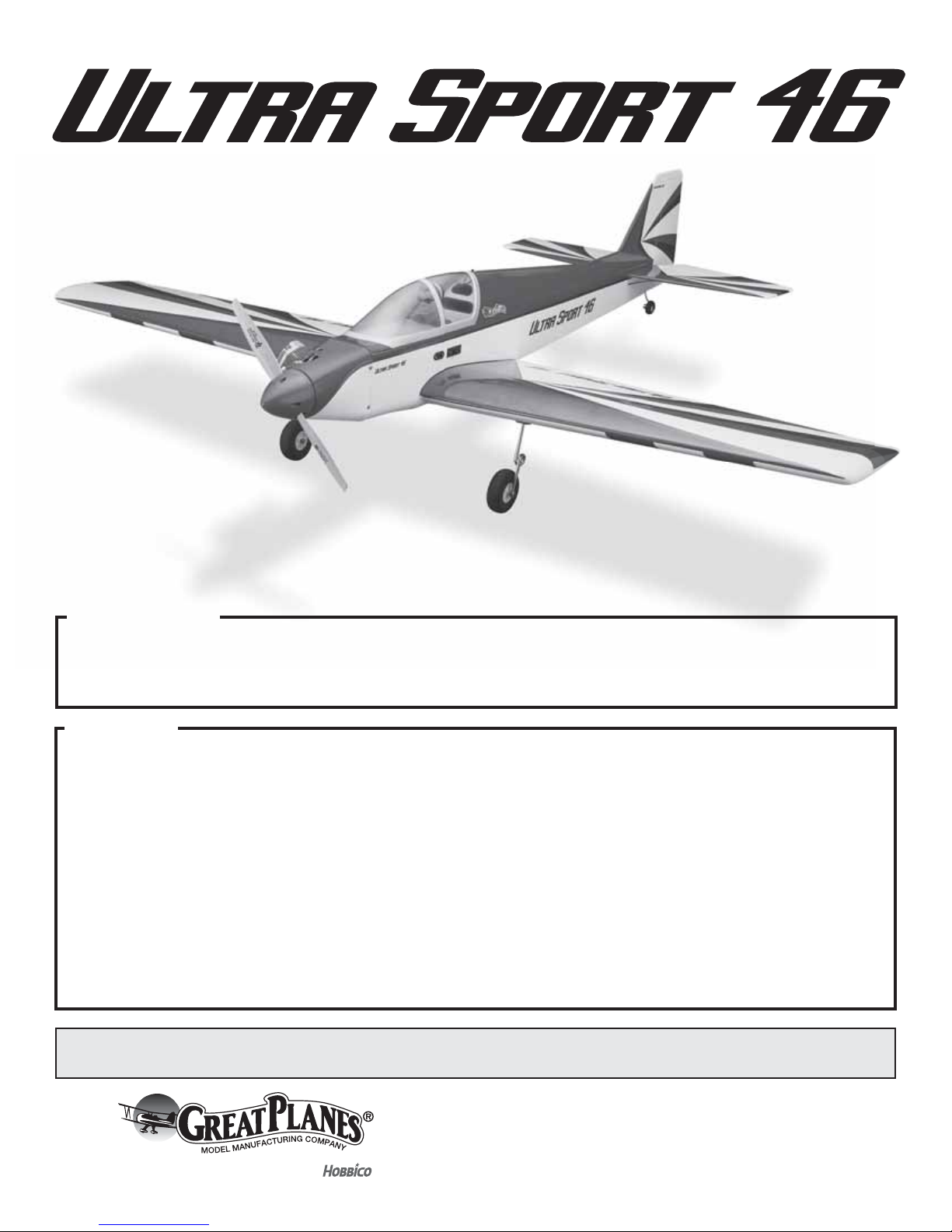
INSTRUCTION MANUAL
SPECIFICATIONS
Wingspan:
Length:
Weight:
55 in [1395mm]
49.5 in [1255mm]
5.5– 6.5 lb [2493– 2947 g]
Wing Area:
Wing Loading:
Radio: 5 channel radio
2
564 in
[36.4 dm2]
22– 26 oz/ft
[67–79 g/dm2]
WARRANTY
Great Planes® Model Manufacturing Co. guarantees this kit to
be free from defects in both material and workmanship at the
date of purchase. This warranty does not cover any component
parts damaged by use or modication. In no case shall Great
Planes’ liability exceed the original cost of the purchased kit.
Further, Great Planes reserves the right to change or modify this
warranty without notice.
In that Great Planes has no control over the nal assembly or
material used for nal assembly, no liability shall be assumed nor
accepted for any damage resulting from the use by the user of
the nal user-assembled product. By the act of using the
user-assembled product, the user accepts all resulting liability.
If the buyer is not prepared to accept the liability associated
with the use of this product, the buyer is advised to return
READ THROUGH THIS MANUAL BEFORE STARTING CONSTRUCTION. IT CONTAINS IMPORTANT
INSTRUCTIONS AND WARNINGS CONCERNING THE ASSEMBLY AND USE OF THIS MODEL.
Engine: .46 - .55
2
.70 (11.5cc) 4-stroke glow engine
[ 7-9 cc] 2-stroke glow engine,
Motor: Great Planes RimFire .55
(42-60-480) Outrunner Brushless
this kit immediately in new and unused condition to the
place of purchase.
To make a warranty claim send the defective part or item to
Hobby Services at the address below:
Hobby Services
3002 N. Apollo Dr. Suite 1
Champaign IL 61822 USA
Include a letter stating your name, return shipping address, as
much contact information as possible (daytime telephone
number, fax number, e-mail address), a detailed description of
the problem and a photocopy of the purchase receipt. Upon
receipt of the package the problem will be evaluated as quickly
as possible.
© 2016 Great Planes Model Mfg. A subsidiary of Hobbico,
®
Inc.
Champaign, Illinois
(217) 398-8970, Ext 5
airsupport@greatplanes.com
GPMA1015

TABLE OF CONTENTS
INTRODUCTION . . . . . . . . . . . . . . . . . . . . . . . . . . . . . . . . 2
Academy of Model Aeronautics. . . . . . . . . . . . . . . . . . 2
SAFETY PRECAUTIONS . . . . . . . . . . . . . . . . . . . . . . . . . 2
DECISIONS YOU MUST MAKE . . . . . . . . . . . . . . . . . . . . 3
Glow Engine. . . . . . . . . . . . . . . . . . . . . . . . . . . . . . . . . 3
Other Accessories for a Glow Engine . . . . . . . . . . . . . 3
Brushless Electric Motor . . . . . . . . . . . . . . . . . . . . . . . 3
Radio Equipment . . . . . . . . . . . . . . . . . . . . . . . . . . . . . 3
ADDITIONAL ITEMS REQUIRED . . . . . . . . . . . . . . . . . . . 4
Adhesive and Building Supplies . . . . . . . . . . . . . . . . . 4
Covering Tools . . . . . . . . . . . . . . . . . . . . . . . . . . . . . . . 4
Optional Supplies and Tools . . . . . . . . . . . . . . . . . . . . 4
IMPORTANT BUILDING NOTES . . . . . . . . . . . . . . . . . . . 4
KIT CONTENTS. . . . . . . . . . . . . . . . . . . . . . . . . . . . . . . . . 5
MODEL INSPECTION . . . . . . . . . . . . . . . . . . . . . . . . . . . . 5
ORDERING REPLACEMENT PARTS . . . . . . . . . . . . . . . . 5
PREPARATIONS . . . . . . . . . . . . . . . . . . . . . . . . . . . . . . . . 6
ASSEMBLE THE WING. . . . . . . . . . . . . . . . . . . . . . . . . . . 6
Aileron Servo Installation . . . . . . . . . . . . . . . . . . . . . . . 6
Join the Wing Panels . . . . . . . . . . . . . . . . . . . . . . . . . . 9
Install the Retracts . . . . . . . . . . . . . . . . . . . . . . . . . . . 10
ASSEMBLE THE FUSELAGE . . . . . . . . . . . . . . . . . . . . . 12
Install the Tail . . . . . . . . . . . . . . . . . . . . . . . . . . . . . . . 12
Install the Rudder and Elevator Servo . . . . . . . . . . . . 14
Electric Motor Installation . . . . . . . . . . . . . . . . . . . . . 16
Glow Engine Installation . . . . . . . . . . . . . . . . . . . . . . 18
Install the Cowl . . . . . . . . . . . . . . . . . . . . . . . . . . . . . 23
Apply the Decals . . . . . . . . . . . . . . . . . . . . . . . . . . . . 24
GET THE MODEL READY TO FLY . . . . . . . . . . . . . . . . . 25
Check the Control Directions. . . . . . . . . . . . . . . . . . . 25
Set the Control Throws . . . . . . . . . . . . . . . . . . . . . . . 25
Finish the Model . . . . . . . . . . . . . . . . . . . . . . . . . . . . 26
Balance the Model Laterally . . . . . . . . . . . . . . . . . . . 27
Balance the Model (C.G.). . . . . . . . . . . . . . . . . . . . . . 27
PREFLIGHT . . . . . . . . . . . . . . . . . . . . . . . . . . . . . . . . . . . 27
Identify Your Model . . . . . . . . . . . . . . . . . . . . . . . . . . 27
Charge the Batteries . . . . . . . . . . . . . . . . . . . . . . . . . 27
Ground Check and Range Check . . . . . . . . . . . . . . . 27
ENGINE SAFETY PRECAUTIONS . . . . . . . . . . . . . . . . . 28
ELECTRIC MOTOR SAFETY PRECAUTIONS. . . . . . . . 28
AMA SAFETY CODE (excerpts) . . . . . . . . . . . . . . . . . . . 29
General. . . . . . . . . . . . . . . . . . . . . . . . . . . . . . . . . . . . 29
Radio Control. . . . . . . . . . . . . . . . . . . . . . . . . . . . . . . 29
FLYING . . . . . . . . . . . . . . . . . . . . . . . . . . . . . . . . . . . . . . . 29
Fuel Mixture Adjustments . . . . . . . . . . . . . . . . . . . . . 29
Takeoff . . . . . . . . . . . . . . . . . . . . . . . . . . . . . . . . . . . . 29
Flight . . . . . . . . . . . . . . . . . . . . . . . . . . . . . . . . . . . . . 30
Landing . . . . . . . . . . . . . . . . . . . . . . . . . . . . . . . . . . . 30
INTRODUCTION
In 1989 the very successful Great Planes Ultra Sport .40 kit
was introduced. Many modelers learned to y aerobatics
with this plane. We are proud to bring you the great ying
Ultra Sport .46/EP in the ARF version. It has been updated
to use an electric motor or a glow engine. Unlike the kit, the
ARF version will have you enjoying the smooth aerobatic
performance in just a few hours.
For the latest technical updates or manual corrections to the
Ultra Sport .46/EP visit the Great Planes web site at www.
greatplanes.com. Open the “Airplanes” link, then select Ultra
Sport .46/EP. If there is new technical information or changes
to this model a “tech notice” box will appear on the page.
Academy of Model Aeronautics
If you are not already a member of the AMA, please join! The
AMA is the governing body of model aviation and membership
provides liability insurance coverage, protects modelers’
rights and interests and is required to y at most R/C sites.
Academy of Model Aeronautics
5151 East Memorial Drive
Muncie, IN 47302-9252
Tele. (800) 435-9262
Fax (765) 741-0057
Or via the Internet at: http://www.modelaircraft.org
IMPORTANT!!! Two of the most important things you can
do to preserve the radio controlled aircraft hobby are to
avoid ying near full-scale aircraft and avoid ying near or
over groups of people.
FAA INFO
As a new owner of an unmanned aircraft system (UAS), you
ar e requ ired to pla ce yo ur FA A numbe r on or in yo ur pla ne. I t
is your responsibility to operate this vehicle safely following
the FAA rules. Please contact your local authorities to nd
out the latest rules and regulations.
In the United States, please visit:
knowbeforeyou y.org faa.gov/uas
SAFETY PRECAUTIONS
Protect Your Model, Yourself & Others…
Follow These Important Safety Precautions
1. Your Ultra Sport .46/EP should not be considered a toy, but
rather a sophisticated, working model that functions very
much like a full-size airplane. Because of its performance
capabilities, the Ultra Sport .46/EP, if not assembled and
operated correctly, could possibly cause injury to yourself
or spectators and damage to property.
2

2. You must assemble the model according to the
instructions. Do not alter or modify the model, as doing
so may result in an unsafe or un yable model. In a few
cases the instructions may differ slightly from the photos.
In those instances the written instructions should be
considered as correct.
3. You must take time to build straight, true and strong.
DECISIONS YOU MUST MAKE
Glow Engine
The Ultra Sport .46/EP is suited for a .46 – .55 2-stroke or .70
4-stroke glow engine. The O.S. Max .55AX (OSMG0557) is
illustrated in this manual with the stock muf er.
4. You m ust use an R/C r adio syste m that is in good co nditi on,
a correctly sized engine, and other components as
speci ed in this instruction manual. All components must
be correctly installed so that the model operates correctly
on the ground and in the air. You must check the operation
of the model and all components before every ight.
5. If you are not an experienced pilot or have not own this
type of model before, we recommend that you get the
assistance of an experienced pilot in your R/C club for
your rst ights. If you’re not a member of a club, your
local hobby shop has information about clubs in your area
whose membership includes experienced pilots.
6. While this kit has been ight tested to exceed most
normal use, if the plane will be used for extremely high
st ress yi ng, s uch as r acing, or i f an en gine larger than
one in the recommended range is used, the modeler is
responsible for taking steps to reinforce the high stress
points and/or substituting hardware more suitable for
the increased stress.
7. WARNING: The cowl included in this kit is made of
berglass, the bers of which may cause eye, skin and
respiratory tract irritation. Never blow into a part to remove
berglass dust, as the dust will blow back into your eyes.
Always wear safety goggles, a particle mask and rubber
gloves when grinding, drilling and sanding berglass
parts. Vacuum the parts and the work area thoroughly
after working with berglass parts.
Other Accessories for a Glow Engine
❍ ¼" [6 mm] R/C Foam Rubber (HCAQ1000)
❍ Great Planes Dead Center Hole Locator (GPMR8130)
❍ 6-32 Tap and Drill Set (DUBR0510)
❍ Suitable propeller for your engine
Brushless Electric Motor
❍ Great Planes RimFire .55 [42-60-480] Outrunner
Brushless Motor (GPMG4715)
❍ Castle Creations Phoenix Edge Light 75 (CSEM1200)
❍ FlightPower LiPo FP30 6S 22.2V 3,800mAh or FP50
5,000mAh 22.2V 3,600 LiPo Batteries (FPWP3386 or
FPWP5366)
❍ 15x8 E Propeller (XOAQ4055) (APCQ4013)
Radio Equipment
The Ultra Sport .46/EP can be own with a minimum of a
5-channel radio. One channel each is used for the throttle,
elevator, rudder, ailerons and retracts.
❍ Futaba 6J 6-Channel S-FHSS System (FUTK6000)
OR
❍ Tactic TTX650 6-channel programmable radio
(TACJ2650)
We, as the kit manufacturer, provide you with a top quality,
thoroughly tested product and instructions, but ultimately
the quality and yability of your nished model depends on
how you build it; therefore, we cannot in any way guarantee
the performance of your completed model, and no representations are expressed or implied as to the performance
or safety of your completed model.
NOTE: Some technically-minded modelers who wish to
check the wing, stab and motor thrust angles may do so by
visiting the web site at www.greatplanes.com and clicking
on “Technical Data.”
REMEMBER: Take your time and follow the instructions
to end up with a well-built model that is straight and true.
RECOMMENDED SERVOS
All control surfaces require the use of a high-quality servo
of at least 54 oz-in of torque and a retract servo.
❍ Futaba S9001 Aircraft Coreless BB Servo (FUTM0075)
OR
❍ Tactic TSX40 Standard High-Speed Metal Gear 2BB
Servo (TACM0240)
and
❍ Futaba S3170G Digital Retract Servo w/Planetary Gear
(FUTM0671)
OR
❍ Tower Hobbies TS-63 Low-Pro le Retract BB Servo
(TOWM5230)
❍ (1) Y-harness (FUTM4135) (TACM2751) (for ailerons)
3
ADDITIONAL ITEMS REQUIRED FOR
ELECTRIC MOTOR INSTALLATION
❍ (1) 8" Servo extension (FUTM4140) (for ESC)
OR
❍ (1) 6" Servo extension (TACM2701) (for ESC)
ADDITIONAL ITEMS REQUIRED FOR
GLOW ENGINE INSTALLATION
❍ (1) Heavy duty on/off switch (FUTM4385) (TACM2761)
❍ (1) Ernst Charge Receptacle (ERNM3001)
❍ (1) 1300mAh LiFe receiver battery (HCAM6411)
ADDITIONAL ITEMS REQUIRED
Optional Supplies and Tools
Here is a list of optional tools mentioned in the manual that
will help you build the Ultra Sport .46/EP.
❍ 2 oz. [57g] spray CA activator (GPMR6035)
❍ CA applicator tips (HCAR3780)
❍ CA debonder (GPMR6039)
❍ 36" metal ruler
❍ Pliers with wire cutter (HCAR0625)
❍ Robart Super Stand II (ROBP1402)
❍ Servo horn drill (HCAR0698)
❍ AccuThrow De ection Gauge (GPMR2405)
❍ CG Machine™ (GPMR2400)
❍ Precision Magnetic Prop Balancer™ (TOPQ5700)
Adhesive and Building Supplies
This is the list of Adhesives and Building Supplies that are
required to nish the Ultra Sport .46/EP.
❍ 1/2 oz. [15g] Thin Pro CA (GPMR6001)
❍ Pro 30-minute epoxy (GPMR6047)
❍ Pro 6-minute epoxy (GPMR6045)
❍ Threadlocker thread locking cement (GPMR6060)
❍ Mixing sticks (50, GPMR8055)
❍ Mixing cups (GPMR8056)
❍ Epoxy brushes (6, GPMR8060)
❍ Denatured alcohol (for epoxy clean up)
❍ Masking tape
❍ Drill
❍ Drill bits: 1/16" [1.5mm], 5/64" [2mm], 3/32" [2.5mm],
11/64" (4.5mm), 3/16" [5mm]
❍ Small metal le
❍ Stick-on segmented lead weights (GPMQ4485)
❍ #1 Hobby knife (RMXR6903)
❍ #11 blades (5-pack, RMXR6930)
❍ Rotary tool such as Dremel
❍ Rotary tool reinforced cut-off wheel (GPMR8200)
❍ Great Planes Dead Center hole locator (GPMR8130)
❍ #64 Rubber Bands (HCAQ2020)
IMPORTANT BUILDING NOTES
● Anytime thin CA glue is recommended
you will see this symbol. When threading
screws into wood, we recommend that
rst the screw be installed. Then, remove
the screw and apply a couple of drops
of thin CA in the hole to harden the
threads. After the CA has hardened,
reinstall the screw.
● Anytime threadlocker is recommended
you will see this symbol. We recommend
that anytime a threaded screw or nut is
installed, a drop of medium threadlocker
be applied to the threads. An exception:
Do not use threadlocker on screws
installed in the nylon control horns.
● Anytime epoxy is recommended you will
see this symbol. 6-minute epoxy can be
used most of the time, but if a step will
require time to assemble, 30-minute
epoxy is recommended.
Covering Tools
❍ Top Flite MonoKote Sealing Iron (TOPR2100)
❍ Top Flite Hot Sock Iron Cover (TOPR2175)
❍ Top Flite MonoKote Trim Seal Iron (TOPR2200)
❍ Top Flite MonoKote Heat Gun (TOPR2000)
❍ Coverite 21st Century Sealing Iron (COVR2700)
❍ Coverite 21st Century Cover Sock (COVR2702)
❍ Coverite 21st Century Trim Sealing Iron (COVR2750)
● Anytime a hole needs to be drilled
you will see this symbol with the
recommended size drill bit.
● Denatured alcohol is great for
cl eaning epox y from sur faces b efore
the epoxy cures.
● When connecting servo extensions
to servos, we recommend that the
connection be secured with heat
shrink or tape (not included).
4
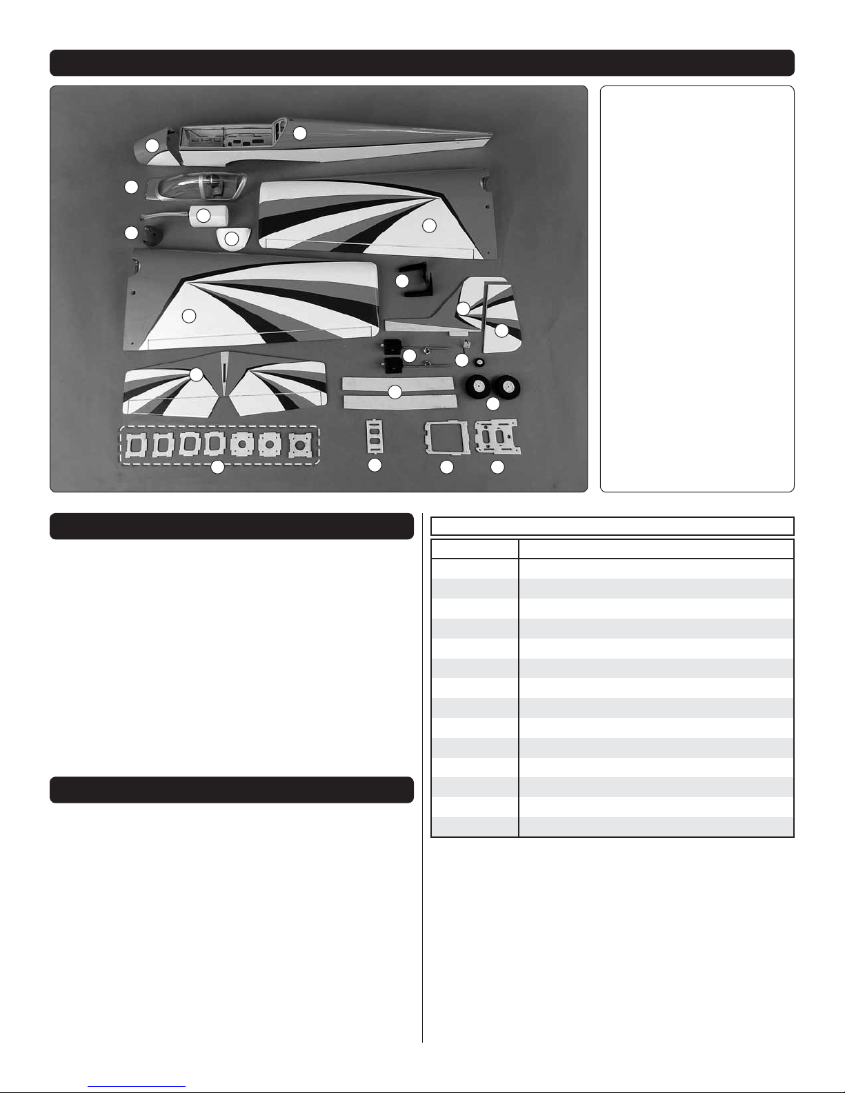
KIT CONTENTS
1.
Fuselage
2.
20
2
5
6
4
7
11
1
3
8
9
10
12
15
16
13
14
17 1819
Canopy/ Hatch
3.
Left Wing
4.
Right Wing
5.
Fuel Tank
6.
Spinner
7.
Belly Pan
8.
Engine Mount
9.
Vertical Fin
10.
Rudder
11.
Horizontal Stabilizer
12.
Retracts
13.
Tail Wheel
14.
Main Wheels
15.
Wing Joiner
16.
Fuel Tank Tray
17.
Forward Sub Tray
18.
Forward Battery Tray
19.
EP Motor Box Parts Set
20.
Cowl
MODEL INSPECTION
Before star ting to build, inspect the parts to make sure they
are of acceptable quality. If any parts are missing or are not of
acceptable qua lity, or if you nee d assistance with assembly,
contact Product Support. When reporting defective or
missing parts, use the part names exactly as they are written
in the instruction manual.
Great Planes Product Support
3002 N Apollo Drive, Suite 1 Ph: (217) 398-8970, ext. 6
Champaign, IL 61822 Fax: (217) 398-7721
E-mail: airsupport@greatplanes.com
ORDERING REPLACEMENT PARTS
Replacement parts for the Great Planes Ultra Sport .46/EP
are available using the order numbers in the Replacement
Parts List that follows. The fas test, most e c onomi c al servic e
ca n be provide d by your h obby dealer o r mail - order c ompany.
Not all parts are available separately (an aileron cannot be
purchased separately, but is only available with the wing kit).
Replacement parts are not available from Product Support,
but can be purchased from hobby shops or mail order/Internet
order rms. Hardware items (screws, nuts, bolts) are also
available from these outlets.
REPLACEMENT PARTS LIST
Order No. Description
GPMA2015
GPMA2016
GPMA2017
GPMA2018
GPMA2019
GPMA2020
GPMA2021
GPMA2022
GPMA2023
GPMA2024
GPMA2025
GPMA2026
GPMA2027
GPMA2028
Wing
Fuselage
Tail Surface Set
Canopy/Hatch
Cowl
Landing Gear Leg Set L /R
Retracts Only Set
Retractable Landing Gear Set
Spinner
Tailwheel Set
Axle Set
Fuel Tank
EP Motor Mount Set
Decals
To locate a hobby dealer, visit www.greatplanes.com and
click on “Where to Buy”. Follow the instructions provided on
the page to locate a U.S., Canadian or International dealer.
5
PREPARATIONS
1. Firmly pull on each of the control surfaces to con rm
❏
they are securely glued. If they are not, apply a few drops of
thin CA to each side of the hinge.
2. Tighten the covering with a covering iron set on low
❏
temperature as needed.
ASSEMBLE THE WING
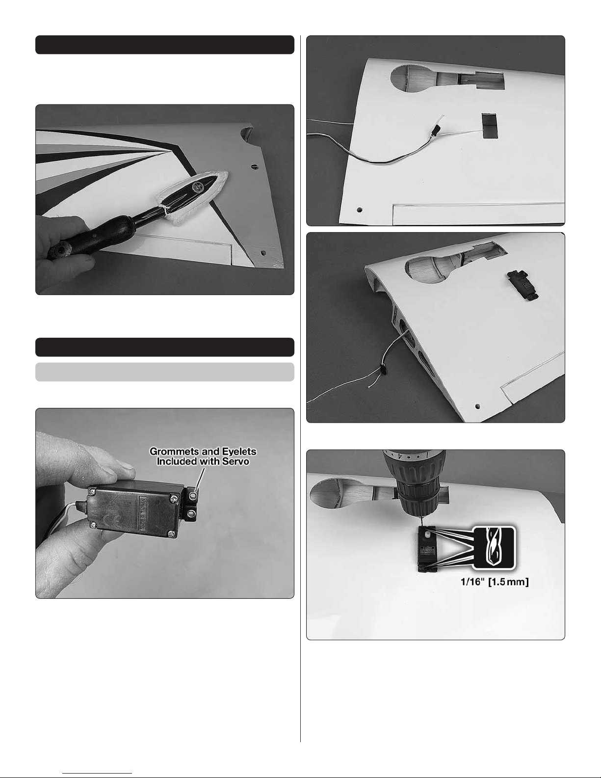
Aileron Servo Installation
Begin with the left wing panel.
1. Install grommets and eyelets.
❏
2. Route the servo lead through the wing.
❏
3. Drill servo screw mounting holes.
❏
6
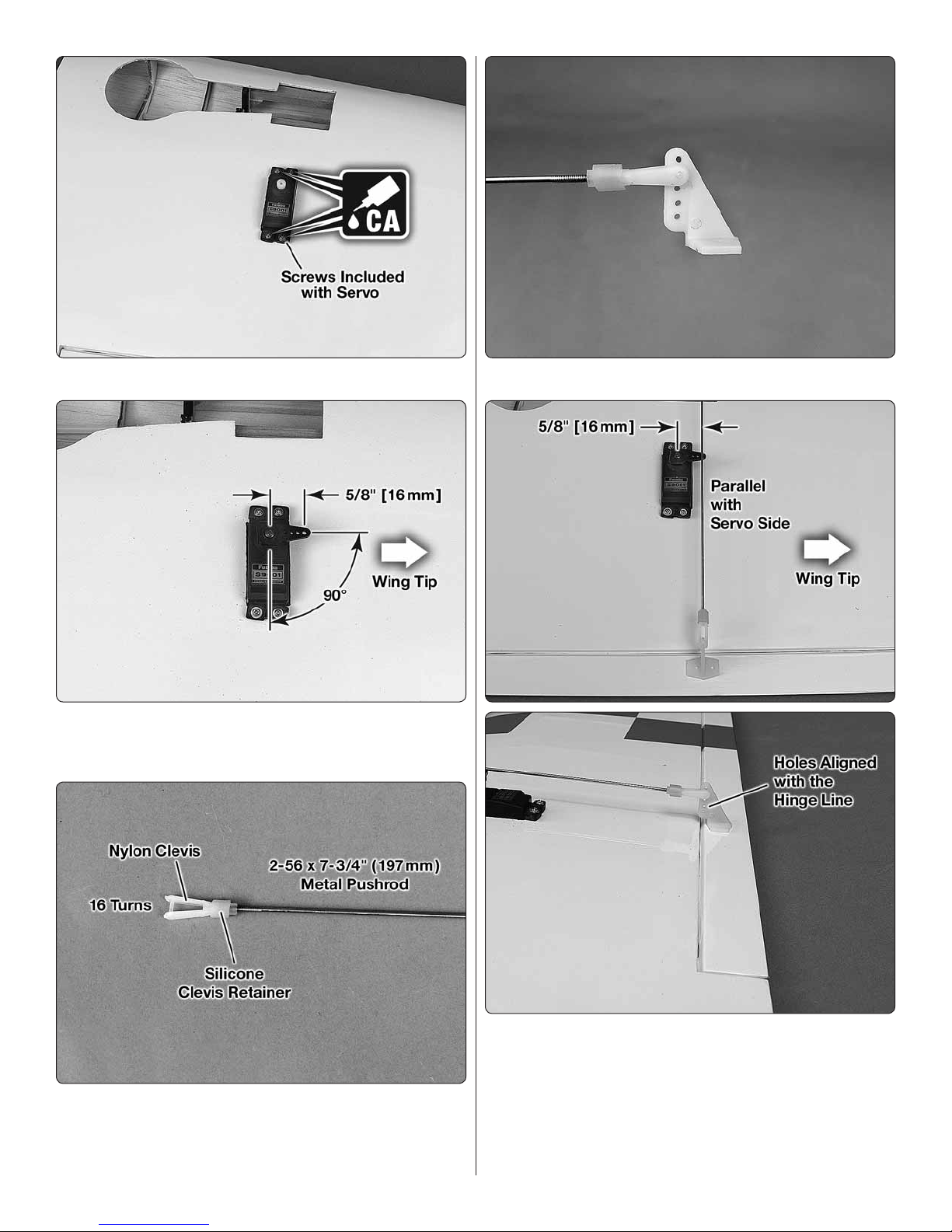
4. Install servo screws.
❏
5. Plug the servo into the receiver. Switch on the transmitter
❏
and connect a receiver battery to the receiver. Center the
aileron servo trim. Install the servo horn.
7. Attach clevis to control horn.
❏
6. Install the nylon clevis.
❏
8. Position control horn on aileron.
❏
7
9. Mount control horn.
❏
10. Install the Faslink.
❏
11. Repeat steps 1 – 10 to install the aileron servo in the
❏
right wing.
8
Join the Wing Panels
1. Glue the two plywood wing joiners together.
❏
4. Install the two 8 x 30mm nylon wing dowels.
❏
2. Install the 5 x 25mm nylon alignment pin.
❏
3. Route the servo leads out the two holes in the top of
❏
the wings.
5. Without glue, insert the plywood wing joiner in one
❏
wing half and test t the wing halves together to check the t.
Make sure both wing halves t together at the root without
any gaps.
6. Gather everything needed to glue the two wing halves
❏
together including 30-minute epoxy, mixing sticks, mixing cup,
epoxy brush, #64 rubberbands, masking tape, 12" (305mm)
long wire or small diameter dowel, denatured alcohol and
paper towels.
7. Mix 2 oz. (59.1cc) of 30-minute epoxy. Working quickly,
❏
pour a generous amount into the joiner pocket of one wing
half. Use the wire or dowel to thoroughly distribute the epoxy,
9
coating all surfaces inside the joiner pocket. Coat the root rib
and one half of the wing joiner. Insert the wing joiner in the
wing. Coat the joiner pocket in the other wing half and the
other end of the wing joiner. Join the wing halves together.
Use the rubberbands to hold the leading and trailing edges
of the wing together. Stand the wing up on end and use
paper towels dampened with denatured alcohol to remove
the excess epoxy that squeezes out. Use masking tape to
hold the wing halves in alignment if necessary.
8. After the epoxy cures, remove the rubberbands and
❏
masking tape.
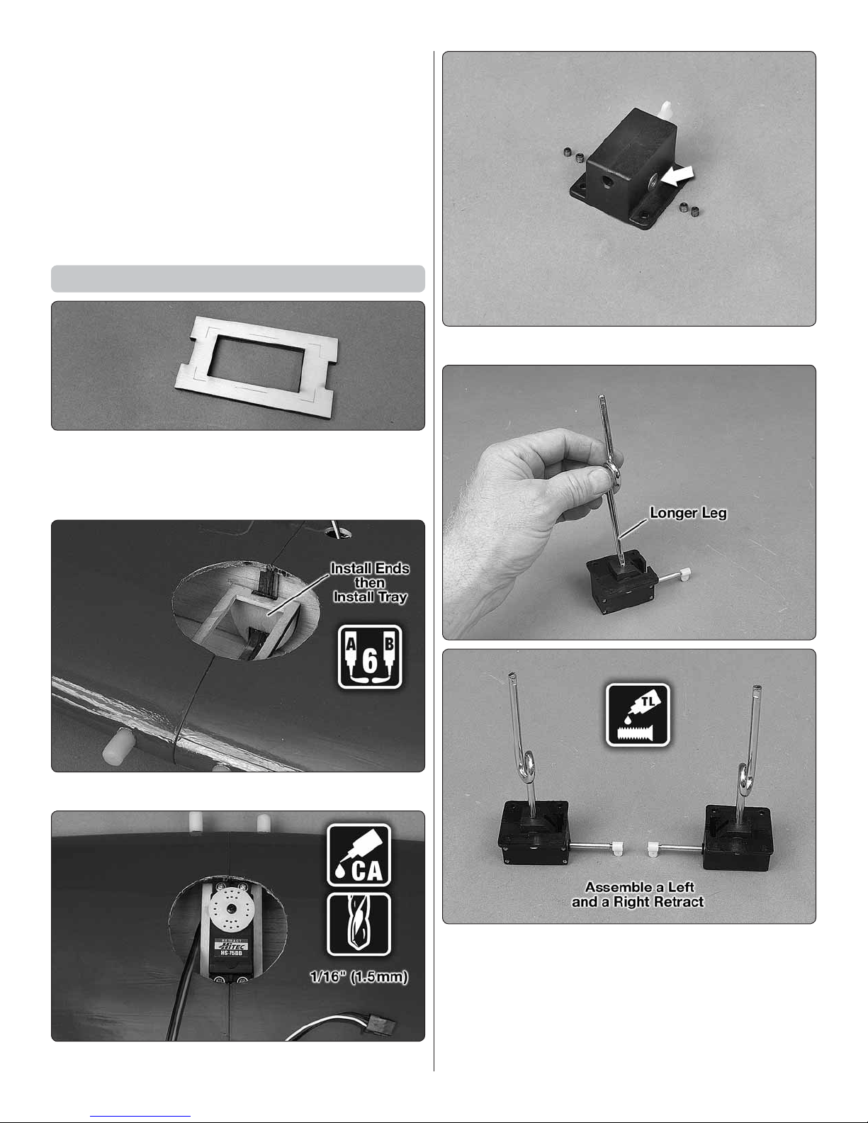
Install the Retracts
1. The retract servo tray is cut to t the Futaba S3170G
❏
retract servo. If the Tower Hobbies TS-63 retract servo is
used, the tray can be trimmed with a hobby knife along the
embossed lines.
4. Remove the four set screws from each retract.
❏
2. Install the retract servo tray.
❏
3. Install the retract servo.
❏
5. Install the gear legs so that the coil is toward the trailing
❏
edge. Tighten a set screw onto the at of the gear leg from
each side. Then tighten the second set screw against the rst.
10
 Loading...