

GREAT PLANES Ultra-Sport 40 ARF Instruction Manual
Almost Ready-to-Fly
Instruction Manual
WARRANTY
Great Planes Model Manufacturing Co. guarantees this kit to be free from defects in both material
and workmanship at the date of purchase. This warranty does not cover any component parts damaged
by use or modification. In no case shall Great Planes' liability exceed the original cost of the
purchased kit. Further, Great Planes reserves the right to change or modify this warranty without
notice.
In that Great Planes has no control over the final assembly or material used for final assembly, no
liability shall be assumed nor accepted for any damage resulting from the use by the user of the final
user-assembled product. By the act of using the user-assembled product, the user accepts all resulting
liability.
If the buyer is not prepared to accept the liability associated with the use of this product, they
are advised to return this kit immediately in new and unused condition to the place of purchase.
READ THROUGH THIS INSTRUCTION MANUAL
FIRST. IT CONTAINS IMPORTANT INSTRUCTIONS
AND WARNINGS CONCERNING THE ASSEMBLY
AND USE OF THIS MODEL.
GPMA1010 V1.2
P.O. BOX 788 URBANA, ILLINOIS 61801 (217) 398-8970
ENTIRE CONTENTS © Copyright 1993

TABLE OF CONTENTS
INTRODUCTION............................................. 3
PRECAUTIONS.............................................. 3
EXPLODED VIEW .......................................... 4
ITEMS REQUIRED......................................... 4
DIE-CUT PARTS............................................. 5
WING ASSEMBLY.......................................... 6
CENTER RIBS (OPTION A)........................... 6
WING JOINERS (OPTION
CENTER RIBS (OPTION B) ........................... 7
WING JOINERS (OPTION B)......................... 7
FIXED GEAR ASSEMBLY (OPTION A).......... 8
RETRACTS (OPTION B)................................ 10
AILERON ASSEMBLY.................................... 12
A)......................... 6
PRE
FLIGHT..................................................
FLYING...........................................................
AMA SAFETY CODE..................................... 27
FLIGHT TRIMMING........................................
FLIGHT TRIMMING CHART .. ........................ 30
TEMPLATES & GAUGES.............................. 31
26
26
29
FUSELAGE ASSEMBLY............................... 13
ENGINE INSTALLATION (2-stroke)
ENGINE INSTALLATION (4-stroke)
MOUNT THE WING
HORIZONTAL STABILIZER ........................... 15
VERTICAL STABILIZER.................................
TAIL GEAR .................................................... 16
GLUING THE HINGES................................... 17
STABILIZER SUPPORT BRACES
RADIO INSTALLATION................................. 19
PUSHRODS ...................................................
CONTROL SURFACE LINKAGE.................... 21
THROTTLE LINKAGE....................................
RECEIVER INSTALLATION........................... 22
FUEL TANK.................................................... 23
FINAL ASSEMBLY........................................ 24
CONTROL
BALANCE THE PLANE LATERALLY.............
THROWS..................................... 2 5
......................................14
............... 13
............... 13
16
................. 18
20
21
25
Metric Conversion Chart
Inches x 25.4 = mm (conversion factor)
1/64"
1/32"
1/16"
3/32"
5/32"
3/16"
3/8"
5/8"
3/4"
1/8" =
1/4"
1/2"
1" =
2" =
3" =
6"
12"
15" =
18"
21"
24"
30" =
36"
=
.4
=
.8
mm
mm
= 1.6mm
= 2.4
=
4
= 4.8
=
=
9.5
= 12.7mm
3.2
6.4
mm
mm
mm
mm
mm
mm
= 15.9mm
=
19
= 152.4mm
= 304.8 mm
= 457.2 mm
= 533.4 mm
= 609.6 mm
mm
25.4 mm
50.8 mm
76.2
mm
381
mm
762 mm
= 914.4mm
2

WARNING! THIS IS NOT A TOY!
THIS IS NOT A BEGINNER'S AIRPLANE!
This R/C kit and the model you will build is not a toy! It is capable of serious bodily harm and property damage.
IT IS YOUR RESPONSIBILITY AND YOURS ALONE — to build this kit correctly, to properly install all R/C
components and flying gear (engine, tank, pushrods, etc.) and to test the model and fly it only with experienced,
competent help, using common sense and in accordance with all safety standards as set down in the Academy of
Model Aeronautics Safety Code. It is suggested that you join the AMA and become properly insured before you
attempt to fly this model. IF YOU A R E JUST STARTING R/C MODELING, CONSULT YOUR LOCAL HOBBY SHOP
OR WRITE T O T H E ACADEMY OF M O D E L AERONAUTICS T O FIND AN EXPERIENCED INSTRUCTOR IN YOUR AREA.
Academy of Model Aeronautics
5151 E. Memorial Drive
Muncie, IN 47302-8252
(317)289-4236
Please inspect all parts carefully before
starting to build! If any parts are missing, broken or
defective, or if you have any questions about
building or flying this airplane, please call us a t (217)
398-8970 and we'll be glad to help. Please find the kit
Congratulations and thank you for purchasing
the Great Panes Ultra-Sport 40 ARF. The Ultra-Sport
incorporates several new design features never before
found in an ARF kit. It utilizes rod-in tube pushrods,
adjustable glass-filled nylon engine mount, multiple color
layers with a glossy, fuel-resistant outer coating and high
quality Great Planes hardware. Stronger and lighter than
a conventional, built-up balsa kit, it provides even better
overall performance!
identification number on the end of the carton and
have it ready when calling.
The Great Planes Ultra-Sport 40 ARF is like the
Ultra-Sport 40 kit. This almost ready to f l y version is one
of the easiest-flying, most aerobatic aircraft ever
designed. It combines the design expertise and high
quality standards of Great Planes kits with state-of-theart AR F technology—for craftsmanship and performance
superior to all other prebuilt models. However, this is
not a beginner's airplane! While the Ultra-Sport 40
AR F is easy to assemble, we must discourage you from
selecting this kit as your first R/C airplane. It is highly
maneuverable, and lacks the self-recovery characteristics
of a good basic trainer such as the Great Planes PT
Series airplanes. On the other hand, if you are confident
with your flying skills and can safely handle aileron
airplanes such as the Great Planes Big Stick Series, the
Ultra-Sport 40 ARF is a n excellent choice.
Precautions
1. You must assemble the plane according to the
instructions. Do not alter or modify the model, as doing
so may result in an unsafe or unflyable model. In a few
cases the instructions may differ slightly from the photos.
In those instances you should assume the written
instructions are correct.
2. You must take time to build straight, true and
strong. IMPORTANT - Glue should never be substituted
for a good-fitting joint. Take a little extra time to get a
and
glue
it
good-fitting joint
neater, and much lighter than a poor fitting joint held
together with an excess of glue!
3
properly.
It
will
be
stronger,
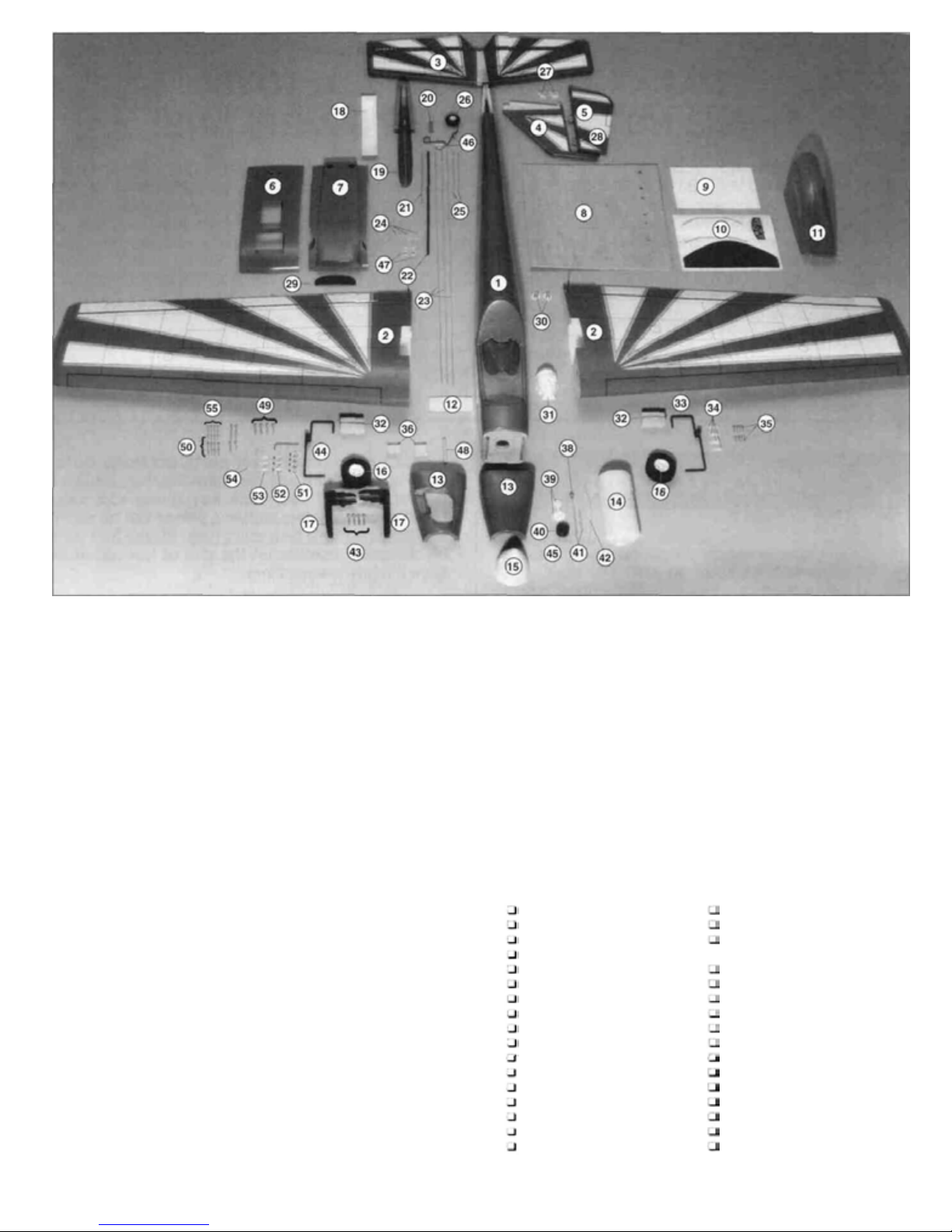
Part# Description Quantity
1........................................Fuselage .....................................................1
2........................................Wing Right & Left ........................................2
3........................................Horizontal Stabilizer & Elevator...................1
4........................................Vertical Stabilizer........................................1
5........................................
6........................................Wing Fairing (top)........................................1
7........................................Wing Fairing (bottom)..................................1
8........................................Die-Cut Plywood......................................... 1
9........................................Die-Cut Plastic............................................1
10......................................Decal Sheet.................................................1
11......................................Canopy........................................................1
12......................................Rear Wing Joiner........................................1
13......................................Cowling .......................................................2
14......................................Fuel Tank....................................................1
15......................................Spinner........................................................1
16......................................Wheel (main gear).......................................2
17......................................Adjustable Engine Mount ............................1
18......................................Die-Cut Plastic Control Horn Backing..........1
19......................................Vertical Stabilizer Fairing ............................1
20......................................Tail Gear Bracket........................................1
21......................................Splined Plastic Tubing.................................1
22......................................Throttle Guide Tube ....................................1
23......................................Pushrod (throttle, elevator, rudder).............3
24......................................Clevis ..........................................................3
25......................................Pushrod (ailerons)......................................2
26......................................Tail Wheel...................................................1
27......................................Control Horn................................................2
28......................................CA Hinges...................................................2
29......................................Foam Rubber Seal......................................1
30......................................Blind Nut.....................................................2
31......................................Pilot.............................................................1
32......................................Landing Gear Mounting Block.....................2
33......................................Main Landing Gear Strut (L)........................2
34......................................Flat Nylon Strap ..........................................4
35......................................#2 x 3/8" Sheet Metal Screw.......................8
36......................................Wing Bolt Plate............................................1
38......................................Fuel Pick-up Weight (clunk) ........................1
39......................................Stopper Disc................................................2
40......................................Rubber Plug................................................1
Rudder
........................................................1
41......................................Aluminum Tube..........................................:2
42....................................... Fu el Tubing .................................................1
43......................................6-32 x 3/4" Machine Screw .........................4
44......................................Main Landing Gear Strut (R) .......................1
45......................................Tank Plug 3 x 18mm S/T Screw..................1
46......................................Tail Gear.....................................................1
47......................................Swivel Clevis...............................................2
48......................................Wing
49......................................#6 x 3/4" Sheet Metal Screw.......................4
50......................................#2 x 3/8" Sheet Metal Screw.....................12
51......................................5/32" Wheel Collar......................................4
52......................................3/32" Wheel Collar......................................2
53......................................Aluminum Spacer........................................2
54......................................#2
55......................................2-56 x 5/8" Machine Screw .........................4
56......................................1/4-20 Nylon Wing Bolt (not shown)............2
57......................................#4
Dowel.................................................1
Washer...................................................4
x 1/2" Sheet Metal Screw (not
shown) .10
Items Required
1 oz. Thin CA Adhesive
1 oz. Medium CA Adhesive
9 oz. 6-minute Epoxy
9 oz. 30-minute
Masking Tape
Petroleum Jelly
IsopropyI Rubbing Alcohol
Thread Locking Compound
Silicone Sealant
Sandpaper Fine/Medium
Pliers
String
Felt-Tip Pen
Clothespins
Mixing Sticks
T-Pins
Hobby Knife, #11
Epoxy
Blades
Ruler
Hand or Electric Drill
Drill Bits 1/16", 3/32", 5/64"
7/64", 1/4"
Foam Rubber
Wing Seating Tape
#64 Rubber Bands
Epoxy Brushes
Mixing Cups
Paper Towels
Files, Flat & Round
Screwdrivers
5/32" Adjustable
Pushrod Connectors (opt.)
Retract Servo (opt.)
Retracts (HCAP4010) (opt.)
Retract Pushrod Wire 2-56 (opt.)
Axle
4
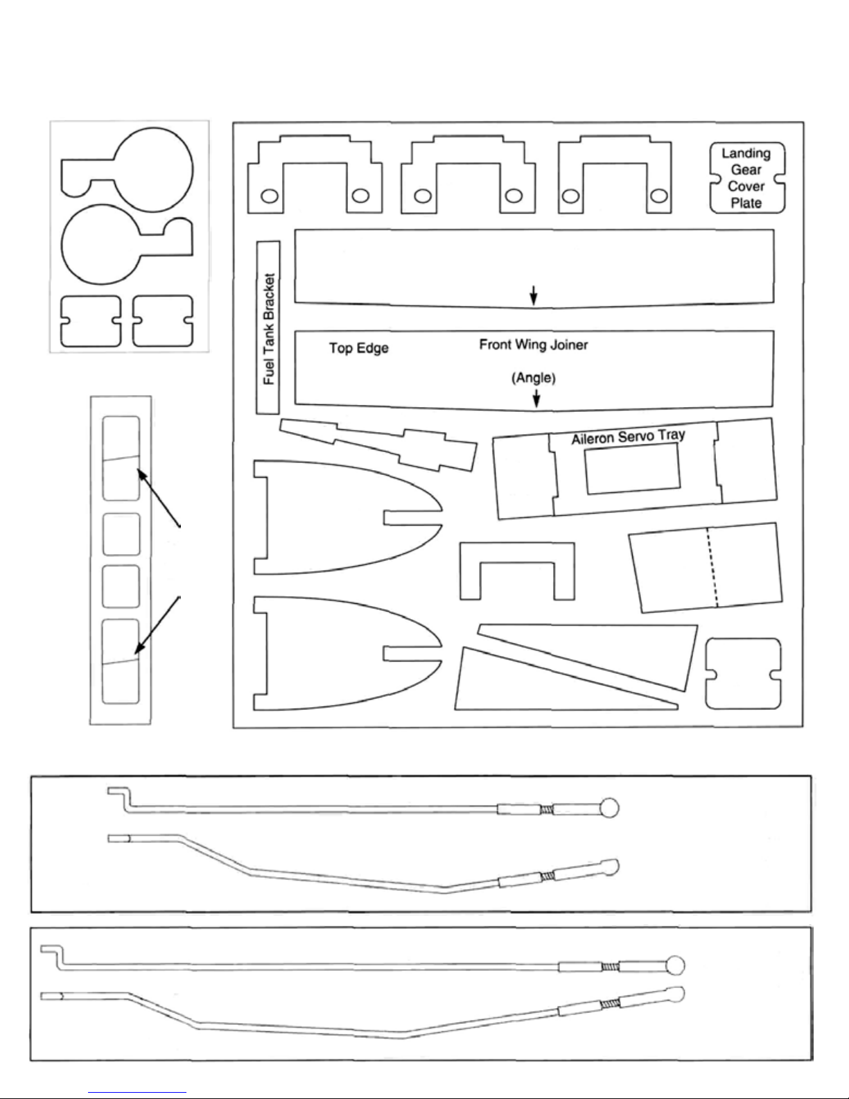
Die-Cut Parts
Plastic Sheet 1/8" (3mm) Plywood Sheet
Wheel Well
Wheel Well
Cover
Mount
Cover
Plastic Sheet
Cover
Mount
Cover
Support
Control
Horn
Plates
Wing
Mounting
Plate
Top Edge
Stabilizer Platform
Front Center Rib
Wing
Mounting
Plate
Front Wing Joiner
Retract
Servo Tray
(Angle)
Servo
Tray
Mount
Wing
Mounting
Plate
Servo
Tray
Mount
Wing
Bolt
Plates
Right Retract Pushrod
Front Center Rib
Top View
Side View
Top View
Side View
Aft Center Rib
Aft Center Rib
Landing
Gear
Cover
Plate
Not Actual Size
Template for
Hobbico Retract
Pushrod
(Not Included)
Actual Size
Template for
Hobbico Retract
Pushrod
(Not Included)
Left Retract Pushrod
Actual Size
5
Center Ribs and Wing Joiners
Fixed Gear (Option A)
(Skip Steps 1-6 Option A if retracts are to be installed.)
(Continue on page 7.)
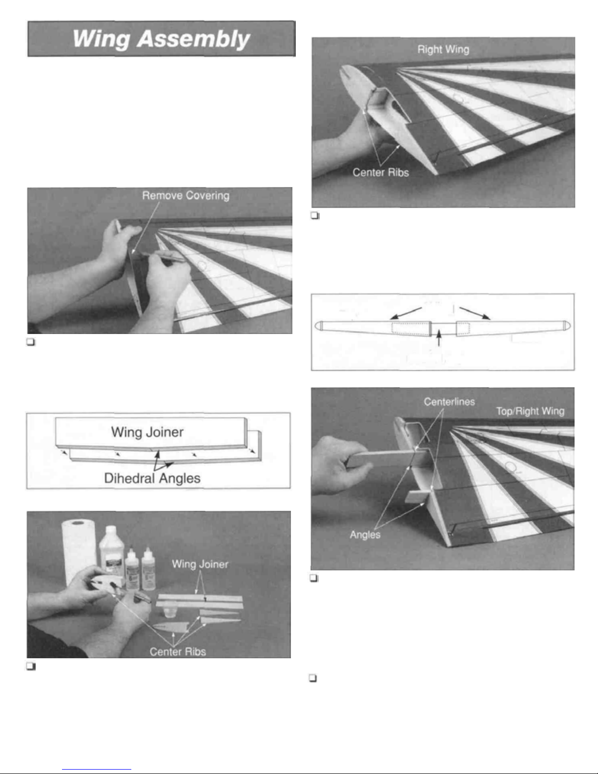
Remove the Foam Covering
Glue the Center Rib on the Wing
3. Trial fit the center ribs on both wing halves, the ribs
should not protrude beyond the outer covering of the wing.
Lightly sand the ribs until they are flush with the wing
covering. Use 6-minute epoxy to glue the plywood center
ribs to the right wing half.
Glue the Wing Joiners into the Wing
1. Remove the foam covering from the aileron servo
opening. The covering has been partially precut for exact
location.
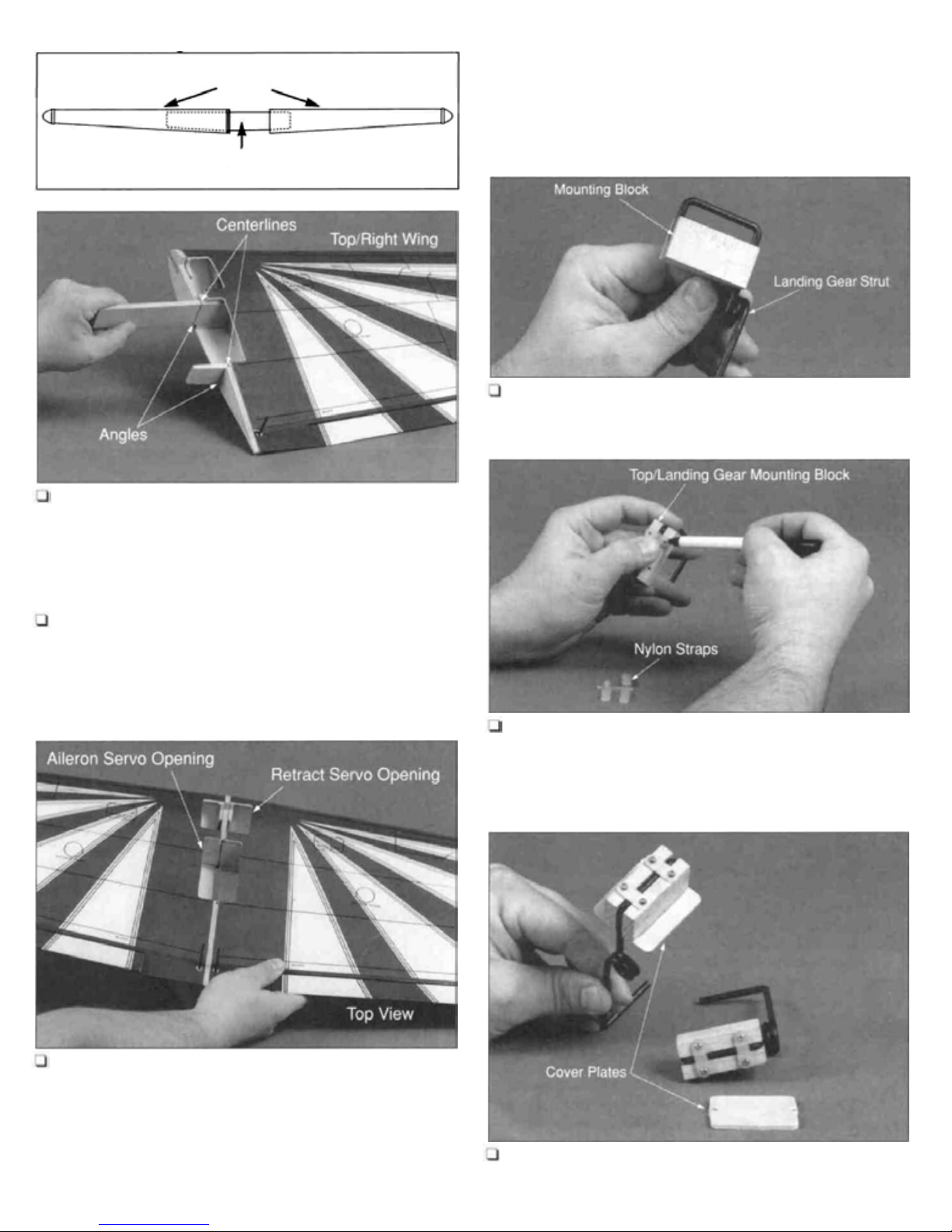
Glue the Center Ribs & Wing Joiners
Top
4. Draw a centerline on both of the wing joiner pieces.
Trial fit the wing joiners into both wing halves. A snug fit is
desirable. If the joiners do not f it properly, lightly sand the
excess epoxy and uneven surface joints from the joiner
edges and sides. Note: The plywood and balsa wing
joiners have a slight dihedral angle on one edge. This
angle should be on the bottom of the wing.
Wing
Bottom
Dihedral Angles
2. Carefully glue the plywood center ribs and wing
joiners together using 6-minute epoxy. The plywood joiner
has a slight angle on one edge. Place these angles
adjacent with each other. Use clothespins to clamp the
joiner and ribs together. Remove the excess epoxy on the
edge of the ribs and joiner using a paper towel and rubbing
alcohol.
5. Use 6-minute epoxy to glue the front and rear wing
joiners into the right wing half. Before the epoxy cures,
make sure the joiners are straight and in good contact with
the wing spars. Wipe off any excess epoxy on the ribs or
on the wing covering with a paper towel and rubbing
alcohol.
6
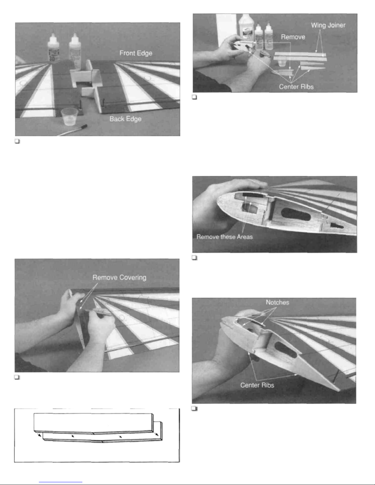
Join the Wing
6. Trial f it the tw o wing halves together. The wing halves
should seat together without any gaps and the front and
back edges of each wing should line up with each other.
Completely cover the wing joiners, spars and center ribs
with 30-minute epoxy. Slide the two wing halves together,
using masking tape to hold the wing in proper alignment
until the epoxy cures.
2. Remove the precut area from the front center rib
before gluing. Carefully glue the plywood center ribs and
wing joiner together using 6-minute epoxy. The plywood
joiner has a slight angle on one edge. Place these angles
adjacent with each other. Use clothespins to clamp the
joiners and ribs together. Remove the excess epoxy on the
edge of the ribs and joiner using a paper towel and rubbing
alcohol.
Modify the Wing Rib
Center Ribs and Wing Joiners
Retracts (Option B)
(Skip Steps 1 -7 Option B if fixed landing gear are to be installed.)
(Continue on page 8.)
Remove the Foam Covering
1. Remove the foam covering from the aileron and
retract servo openings. The skin has been partially precut
for exact location.
3. Using a hobby knife, remove the precut areas of the
wing ribs on the two closest ribs to the wing root in both
wing halves.
Glue the Center Rib on the Wing
Glue the Center Ribs & Wing Joiners
Wing Joiner
Dihedral Angles
for a proper fit. The ribs should not protrude past the outer
skin of the wing. Lightly sand the edges of the center ribs
until they are flush with the wing covering. Glue the
plywood center ribs t o the right wing half. Note: Notice the
positions of the notches removed from the center and wing
ribs for the retract pushrods when gluing the plywood rib
onto the wing.
7
Glue the Wing Joiners
Landing Gear Assembly
Top
Wing
Bottom
Wing Joiner
5. Draw a centerline on both of the wing joiner pieces.
Trial fit the wing joiners in both wing halves. A snug fit is
desirable. If the joiners do not fit properly, lightly sand the
excess epoxy and uneven surface joints from the joiner
edges and sides. The plywood joiner has a slight angle
on one side, which should face the bottom of the wing.
Fixed Gear (Option A)
(Skip Steps 1-11 Option A if retracts are being installed.)
(Continue on page 10.)
Assemble the Fixed Landing Gear
1. Place the landing gear mounting block between the
U-bend on the top portion of the main landing gear strut.
Secure the Mounting Blocks
6. Use 6-minute epoxy to glue the front and rear wing
joiners into the right wing half. Before the epoxy cures,
make sure the joiners are straight and in good contact with
the wing spars. Wipe off any epoxy on the ribs or on the
wing covering using a paper towel and rubbing alcohol.
Join
the
Wing 2. Using a pen, place marks on the mounting blocks
7. Trial fit the two wing halves together. The wing halves
should seat together without any gaps and the front and
back edges of each wing should lineup with each other.
Completely, cover the wing joiners, spars and center
ribs.with 30-minute epoxy. Slide the two wing halves
together, using masking tape to hold the wing in proper
alignment until the epoxy cures.
using the flat nylon straps as templates. Predrill the screw
holes using a 1/16" drill bit and secure the strut with two
nylon straps and four #2 x 3/8" sheet metal screws.
Final Assembly
3. Use 6-minute epoxy to glue the plywood landing gear
cover plate to the mounting block.
8
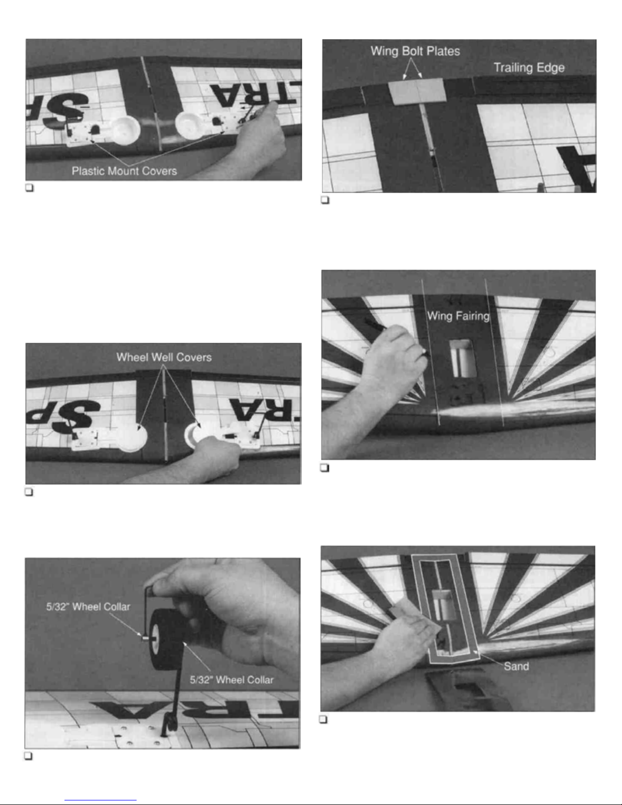
Install the Gear into the Wing Mount the Wing Bolt Plates
4. Place the landing gear into position in the wing.
Locate the plastic landing gear mount covers and glue
them to the plywood mounting plates with thick CA. Trim
out and use the template on page 31 to locate and drill
eight 3/32" holes in both landing gear mounts. Install eight
#4 x 1/2" sheet metal screws into t he holes you just drilled.
Note: The inner four screws secure the plywood plate to
the grooved landing gear block and the outer four screws
secure the plywood plate to the mounting rails in the wing.
7. Using 6-minute epoxy, glue the plywood wing bolt
plates to the bottom of the wing aligned with the trailing edge.
Prepare the Wing Fairing
Install the Wheel Well Covers
5. Locate and glue the two white plastic retract wheel
well covers in place using medium CA.
Mount the Wheel
8. Individually place the top and bottom plastic wing
fairings on the wing and lightly trace its outline onto the wing.
Sand the Fairing and Wing
6. Mount the wheels using the four 5/32" wheel collars.
(One on each side of the wheel.)
9. Use medium grit sandpaper to lightly roughen the
inside of each fairing where it wil l be glued to the wing. The
area to be sanded is shown as a lightened area in the
photograph. This will insure better adhesion of the fairing
to the wing.
9
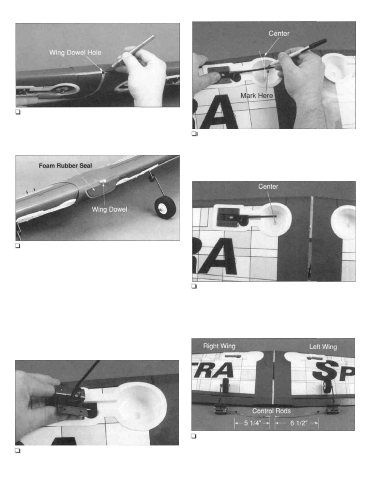
Glue the Fairing to the Wing
Mark the Retract
10. Use thick CA+ to glue the top fairing to the top
the wing. Remove the plastic that is covering the wing
dowel hole on the leading edge of the wing. Proceed to
glue the bottom fairing to the bottom side of the wing
remove the remaining plastic covering the dowel hole.
of
and
Glue the Wing Dowel
11. Use 6-minute epoxy to glue the hardwood wing
dowel into the leading edge of the wing. Work epoxy into
the dowel hole. Apply epoxy to the dowel itself and insert
the dowel. Leave 1/2" of dowel protruding from the wing.
Clean the excess epoxy from the dowel using a paper
towel and rubbing alcohol. Apply the foam rubber seal to
the front edge of the wing fairing. It will help prevent
exhaust residue from leaking into the fuselage.
Landing Gear Assembly
2. Using a pen, mark the landing gear wire at the
center of the wheel well when the retracts are folded into
the wing.
Cut the Gear Wire
3. Bend the landing gear wire at the mark. Install the
wheel on the landing gear wire securing it with a 5/32"
wheel collar. Cut off the excess landing gear wire and file
the end to remove any rough edges.
Retracts (Option B)
(Skip Steps 1-13 Option B if fixed gear has been installed.)
(Continue with Aileron Assembly on page 12.)
Retract Modification
1. Insert the retract into the wing with the main landing gear
wire facing toward the root of the wing when it i s folded down.
Bend the Pushrods
4. Bend the pushrods to match the line drawing on page
5. The pushrods should look like the assembled retracts
shown in the photograph above, if you are using Hobbico
Main Retracts (HCAP4010).
10
 Loading...