

Page 1

SPECIFICATIONS
Wingspan:
Length:
Wing Area:
Weight:
78.5 in [1995mm]
42 in [1065mm]
498 in
2
[32.1 dm
2
]
29– 31 oz [822– 879 g]
Loading:
Motor: RimFire .10 Outrunner
8.4 – 9.0 oz/ft
Wing
[25.6–27.5 g/dm2]
(Included with the Rx-R)
ESC: 40A
(Included with the Rx-R)
WARRANTY
Great Planes® Model Manufacturing Co. guarantees this kit to
be free from defects in both material and workmanship at the
date of purchase. This warranty does not cover any component
parts damaged by use or modication. In no case shall Great
Planes’ liability exceed the original cost of the purchased kit.
Further, Great Planes reserves the right to change or modify this
warranty without notice.
In that Great Planes has no control over the nal assembly or
material used for nal assembly, no liability shall be assumed nor
accepted for any damage resulting from the use by the user of
READ THROUGH THIS MANUAL BEFORE STARTING CONSTRUCTION. IT CONTAINS IMPORTANT
INSTRUCTIONS AND WARNINGS CONCERNING THE ASSEMBLY AND USE OF THIS MODEL.
INSTRUCTION MANUAL
2
the nal user-assembled product. By the act of using the
user-assembled product, the user accepts all resulting liability.
If the buyer is not prepared to accept the liability associated
with the use of this product, the buyer is advised to return
this kit immediately in new and unused condition to the
place of purchase.
To make a warranty claim contact:
greatplanes.com/support
Battery: 2S 2200mAh,
3S 1800mAh LiPo
(LiPo not included)
Propeller: 12 x 6.5 (included)
Radio: 4+ ch. radio, 4 servos
(Servos included with the Rx-R)
© 2018 Great Planes Model Mfg. A subsidiary of Hobbico,® Inc.
GPM A1818 /GP MA1819
Page 2

TABLE OF CONTENTS
Academy of Model Aeronautics
ELECTRIC MOTOR SAFETY PRECAUTIONS. . . . . . . . . 2
LITHIUM BATTERY WARNING. . . . . . . . . . . . . . . . . . . . . 3
ADDITIONAL ITEMS REQUIRED . . . . . . . . . . . . . . . . . . . 3
Radio/Servos . . . . . . . . . . . . . . . . . . . . . . . . . . . . . . . . 3
Motor. ESC, Battery . . . . . . . . . . . . . . . . . . . . . . . . . . . 3
LiPo Battery Charger . . . . . . . . . . . . . . . . . . . . . . . . . . 3
Adhesives, Hardware and Other Accessories . . . . . . . 4
REPLACEMENT PARTS LIST. . . . . . . . . . . . . . . . . . . . . . 4
KIT CONTENTS. . . . . . . . . . . . . . . . . . . . . . . . . . . . . . . . . 4
PREPARATION . . . . . . . . . . . . . . . . . . . . . . . . . . . . . . . . . 5
ASSEMBLE THE WING. . . . . . . . . . . . . . . . . . . . . . . . . . . 6
Hook Up the Ailerons. . . . . . . . . . . . . . . . . . . . . . . . . . 6
Install the Servo Covers. . . . . . . . . . . . . . . . . . . . . . . . 8
Join the Wing Halves . . . . . . . . . . . . . . . . . . . . . . . . . . 9
Mount the Wing . . . . . . . . . . . . . . . . . . . . . . . . . . . . . 10
ASSEMBLE THE FUSELAGE . . . . . . . . . . . . . . . . . . . . . 10
Install the Fin and Stab . . . . . . . . . . . . . . . . . . . . . . . 10
Hook Up the Elevator and Rudder. . . . . . . . . . . . . . . 13
Install the Motor . . . . . . . . . . . . . . . . . . . . . . . . . . . . . 14
Final Assembly. . . . . . . . . . . . . . . . . . . . . . . . . . . . . . 17
PREPARE THE MODEL FOR FLIGHT . . . . . . . . . . . . . . 18
Set the Control Throws . . . . . . . . . . . . . . . . . . . . . . . 18
Arm the ESC. . . . . . . . . . . . . . . . . . . . . . . . . . . . . . . . 19
Set the Fail Safe and the Motor Brake. . . . . . . . . . . . 19
Check the C.G. . . . . . . . . . . . . . . . . . . . . . . . . . . . . . 19
Balance the Model Laterally . . . . . . . . . . . . . . . . . . . 20
PREFLIGHT . . . . . . . . . . . . . . . . . . . . . . . . . . . . . . . . . . . 20
Motor Safety Precautions . . . . . . . . . . . . . . . . . . . . . 20
Range Check . . . . . . . . . . . . . . . . . . . . . . . . . . . . . . . 20
General Pre ight Information. . . . . . . . . . . . . . . . . . . 20
FLYING . . . . . . . . . . . . . . . . . . . . . . . . . . . . . . . . . . . . . . . 21
INTRODUCTION
Thank you for purchasing the Great Planes Tori 2-meter EP
Sailplane! The Tori features a carbon boom, folding prop
and berglass fuselage. This gives you a glider that is steps
above a conventional foam or all-wood glider. The Tori can
be own with either a 2S or 3S LiPo for versatility. See the
Flying section on page 21 for more details.
NOTE: This instruction manual illustrates all the steps
necessary to assemble the ARF (almost ready-to- y) edition
of the Tori. However, the Rx-R (receiver-ready) edition
requires less assembly, so if assembling the Rx-R, simply
skim through the manual and perform only steps that apply.
For the latest technical updates or manual revisions, nd
the Tori on the Great Planes web site at www.greatplanes.
com. If there is new technical information or changes to this
model, a “Tech Notice” box will appear on the page for the
Tori on the Great Planes web site.
If you are not already a member of the AMA, please join! The
AMA is the governing body of model aviation and membership
provides liability insurance coverage, protects modelers’ rights
and interests and is required to y at most R/C sites.
Academy of Model Aeronautics
5151 East Memorial D rive
Muncie, IN 47302-9252
Tele. (800) 435-9262
Fax (765) 741-0057
Or via the Internet at: http://www.modelaircraft.org
IMPORTANT!!! Two of the most important things you can do to
preserve the radio controlled aircraft hobby are to avoid ying near
full-scale aircraft and avoid ying near or over groups of people.
FAA Info
As a new owner of an unmanned aircraft system (UAS) it is
your responsibility to operate this vehicle safely following the
FAA rules. Please contact your local authorities to nd out
the latest rules and regulations. As of this printing, the FAA
does not require an FAA number on your plane. In the United
States, please visit:
knowbeforeyou y.or g
faa.gov/uas.
ELECTRIC MOTOR
SAFETY PRECAUTIONS
WARNING! A spinning propeller has the potential to cause
serious and permanent injury.
WARNING! Once the motor batteries are connected, the
propeller can start spinning at any time. Make sure the Fail
Safe is set on your radio to prevent the motor from starting
if the signal is lost.
WARNING! Stand clear of the propeller when handling
the aircraft. Make sure the aircraft is held securely until the
battery has been disconnected.
While working on your plane, ALWAYS remove the propeller
when the battery is connected.
ALWAYS remove the motor batteries from the plane
when charging.
ALWAYS switch on the transmitter rst, then the receiver.
ALWAYS unplug the motor batteries rst before switching
off the receiver, then transmitter.
NEVER touch the motor during or right after operation. The
motor gets HOT!
NEVER switch off the transmitter with the motor batteries
plugged in.
NEVER reach through the arc of the propeller when plugging
or unplugging the battery into the ESC.
2
Page 3

LITHIUM BATTERY WARNING!
This product recommends the use of a lithium polymer
(LiPo) battery. Improper handling of a LiPo battery
could result in FIRE! A lithium battery re has the
potential to ignite surrounding areas and may cause property
damage or personal injury.
For safe LiPo handling, follow ALL of these guidelines:
MOST IMPORTANT! Never leave the battery or charger
unattended during charging or discharging.
WARNING: Read the entire instruction sheet included with
your motor batteries. Failure to follow the instructions could
cause permanent damage to the battery and its surroundings
and cause bodily harm!
NEVER charge the battery or set the charger on combustible
materials.
NEVER charge the battery inside a vehicle or in a location
that could be damaged in the event of a LiPo re.
NEVER put a LiPo battery in the pocket of any clothing.
NEVER charge the batteries in the plane. Disconnect the
batteries and remove them from the plane immediately
after landing.
NEVER allow the battery to short circuit by touching exposed
wires together. This may cause a re.
NEVER operate or store batteries below 40˚F (4˚C) or above
110˚F (43˚C).
ADDITIONAL ITEMS REQUIRED
ALWAYS follow the charging instructions included with your
charger for charging LiPo batteries. LiPo batteries can cause
serious damage or re if misused.
ALWAYS use a LiPo-approved charger.
ALWAYS set the charger’s output volts to match the
battery volts.
ALWAYS charge a LiPo battery in a reproof location.
ALWAYS balance charge the battery.
ALWAYS store and transport LiPo batteries in a reproof
container away from combustible materials.
ALWAYS KEEP OUT OF THE REACH OF CHILDREN.
ALWAYS keep LiPo batteries out of the reach of animals. A
punctured battery may cause a re.
ALWAYS disconnect the battery and unplug the charger
after the charge is complete.
ALWAYS keep a supply of sand accessible when charging
a LiPo battery. Dumping sand on the battery will assist in
extinguishing a LiPo chemical re.
ALWAYS remove the batteries from the plane after a crash.
Set them aside in a safe location for at least 20 minutes. If
the batteries are damaged in the crash, they could catch
re. If the battery starts to swell, quickly move the battery to
a safe location, preferably outside away from combustible
material. Place it in a bucket, covering the battery with sand.
NEVER use water to try and put out a LiPo re.
NEVER charge or use a battery that is deformed, bent,
crushed, swollen, or has any type of visible damage.
NEVER use a NiCd/NiMH peak charger to charge a
LiPo battery.
NEVER charge in excess of 4.20V p e r cell unless the battery
is rated for a higher voltage.
NEVER charge at currents greater than 1C unless the batte r y
is rated for a higher charge rate.
NEVER trickle-charge a LiPo battery.
NEVER allow the battery temperature to exceed 140°F (60°C).
NEVER disassemble or modify the pack wiring in any way
or puncture the cells, as this may result in a re.
NEVER discharge below 2.7V per cell. It is recommended
to not discharge below 3.7V per cell.
Radio/Servos
A minimum 4-channel radio is required to y the Tori. The
Tactic TTX660 is recommended because of its simple,
exible computer programming and multiple model memory.
The servo tray in the fuselage is sized for Tactic TSX5 micro
servos, but the cutout may be enlarged for other servos.
Because of the Tori’s capability to reach high altitudes, it
is also recommended to use a full-range, dual-diversity
receiver such as the Tactic TR625.
❍ Tactic TTX660 6-channel programmable radio
(TACJ2660)
❍ Tactic TR625 6-channel receiver (TACL0625)
❍ (4) Tactic TSX5 micro high speed servos (TACM0205)
❍ OPTIONAL*: Y-harness for ailerons (FUTM4130).
*If spoilerons are desired, 5-channels will be required and the
aileron servos will have to be connected to separate channels
in the receiver and mixed electronically through programming
in the transmitter. In this case a Y-harness is not used.
Motor , ESC, Battery
The Tori Rx-R includes the recommended RimFire motor and
an ESC with similar speci cations and performance to the
recommended ESC. With the included 12x6.5 folding propeller,
either version of the Tori may be own on a 2S or 3S battery.
The recommended motor, ESC and battery for the Tori:
❍ Great Planes RimFire .10 35-30-1250 Outrunner
Brushless (GPMG4595)
❍ Great Planes Programmable ESC 40A BL 2S-6S
(GPMM2140)
❍ 30C 3S 11.1V 1800mAh LiPo Star (ONXP2243)
OR 30C 2S 7.4V 2200mAh LiPo Star (ONXP2260)
LiPo Battery Charger
A charger capable of charging LiPo batteries is required.
The Triton EQ (GPMM3155) is a suitable charger as it has
plenty of power for charging the LiPos recommended for
the Tori (and larger LiPos as well). The Triton EQ is also
recommended for its versatility in charging all other types of
batteries used in RC and may be powered by either a 12V
DC power source or 110V AC.
3
Page 4
Adhesives, Hardware and
Other Accessories
Other than common hobby tools, here is a list of other items
required to assemble the Tori:
❍ 30-minute epoxy (GPMR6043)
❍ Epoxy brushes (GPMR8060)
❍ Mixin’ cups (GPMR8056)
❍ Mixin’ sticks (GPMR8055)
❍✱ Shoe Goo (DTXC2460)
❍ Threadlocker thread locking cement (GPMR6060)
❍✱ Thin CA (GPMR6001)
❍✱ Medium CA (GPMR6007)
❍✱ CA applicator tips (HCAR3780)
❍✱ CA accelerator (GPMR6035)
❍✱ Clear tape
❍✱
Drills: #55 (.052" [1.3mm]), 1/16" [1.5mm]
OPTIONAL:
❍ Great Planes C.G. Machine (GPMR2400)
❍✱ 3/16" Heat shrink tubing (GPMM1056) (see page 17)
✱ These items not needed for Tori Rx-R
A covering iron with a cover sock may be required for
tightening and re-bonding the covering that may have
loosened between the time the covering was applied and
the time the model was removed from the box. The 21
st
Century Iron is preferred because of its long cord, contoured
shoe and precisely adjustable temperature range.
❍ Coverite 21
st
Century Sealing Iron (COVR2700)
❍ Coverite 21st Century Cover Sock (COVR2702)
REPLACEMENT PARTS LIST
Order No. Description
GPMA4401
GPMA4402
GPMA4403
GPMA4404
GPMA4405
GPMA4406
GPMA4407
GPMA4408
For questions, contact: greatplanes.com/support
Fuselage
Wing Parts Set
Tail Surface Set
Hatch
Propeller Blade Set 12 x 6.5
Spinner/Blade Holder
Aileron Servo Cover
Decals
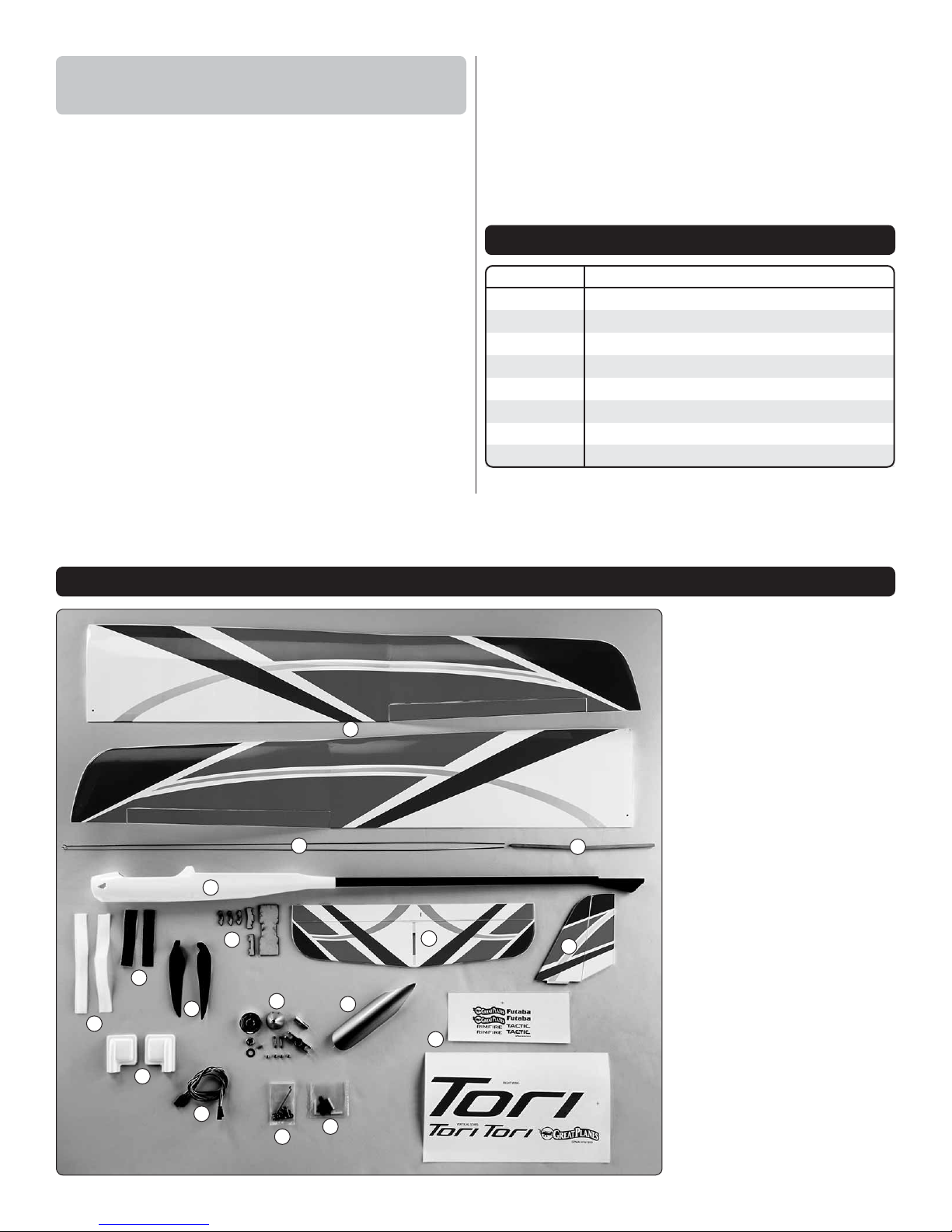
KIT CONTENTS
1. Wi ng Halves
2. Pushrods
1
2
4
7
6
5
10
13
14
11
15
12
16
8
17
3
9
3. Wing Joiner
4. Fuselage
5. Hook & Loop Material
6. Adhesive-Backed Hook
& Loop Material
7. Wire Holders, Pushrod
Brace, Battery Plate
8. Stab
9. Fin
10. Propeller Blades
11. Spinner/Blade Holder
12. Canopy Hatch
13. Aileron Servo Covers
14. Aileron Servo Extensions
(ARF only)
15. Hardware Pack
16. Control Horns
17. D e c al s
4
Page 5
PREPARATION
1. The canopy is held in place with wire rods at both
❏
ends. To remove the canopy, slide it forward and then lift
the back end up.
ASSEMBLE THE WING
Hook Up the Ailerons
You can assemble one wing at a time, or work on both wing
halves simultaneously. The left wing is shown in the photos.
2.
Use a covering iron with a protective cover sock to bond
❏
areas of loose covering back down to the framework or remove
any wrinkles that may have developed after the covering was
applied. Start with low or medium heat to nd the setting that
works best (approximately 275ºF measured on the surface of
the cover sock). Gradually increase the heat as necessary, but
too much heat may cause seams and edges to pull away or
damage the color graphics printed onto the covering, so
proceed with care. As you go, push down on the iron over
sheeted areas to bond the covering to the wood underneath.
3. Stack two or three
❏
paper towel squares on
top of each other and
cut them into small
squares. These squares
may be dampened
with denatured alcohol
when epoxy cleanup is
needed.
5
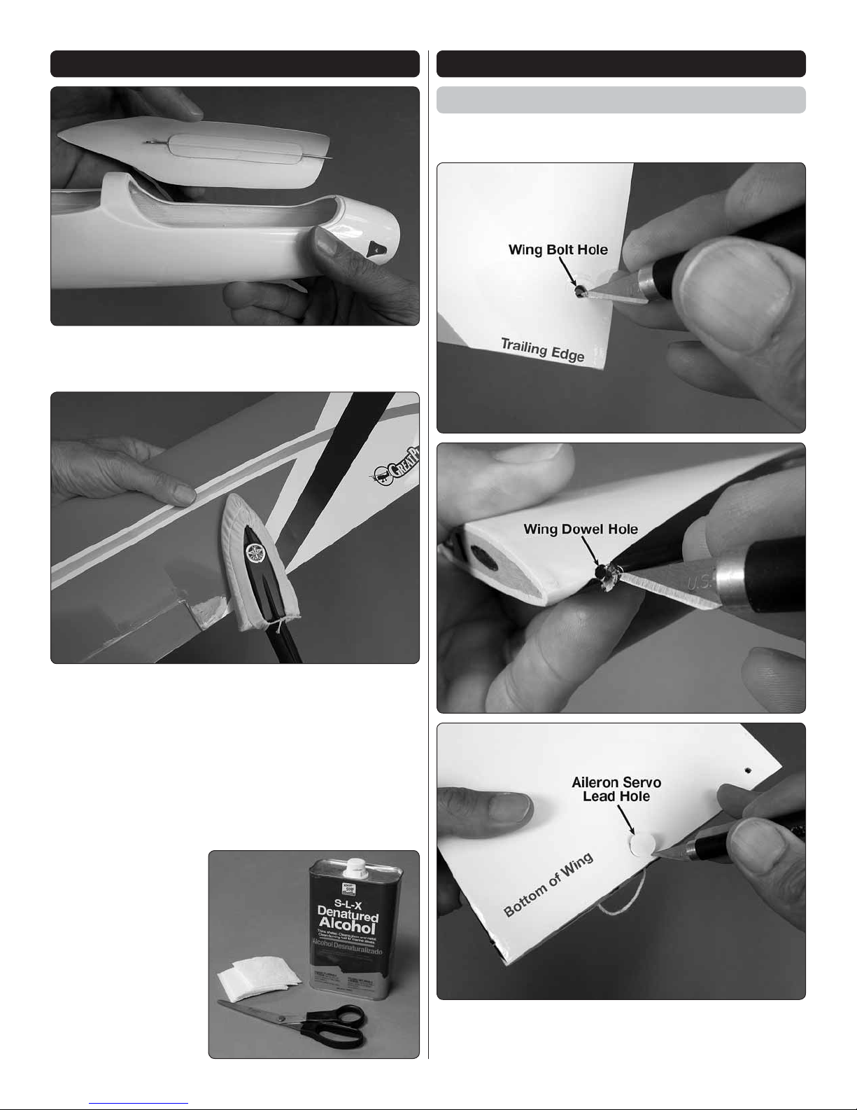
1. Cut the covering from the wing over the wing bolt
❏
holes, the leading edge dowel holes and the servo wire
holes in both wing halves.
Page 6
2. Use an epoxy brush to apply a thin coat of epoxy or
Cut off
Trim
7/16" [11mm]
(4
th
hole in Tactic
servo arm)
❏
medium CA to the inside of the top wing skin in the aileron
servo opening. Allow epoxy to harden before continuing.
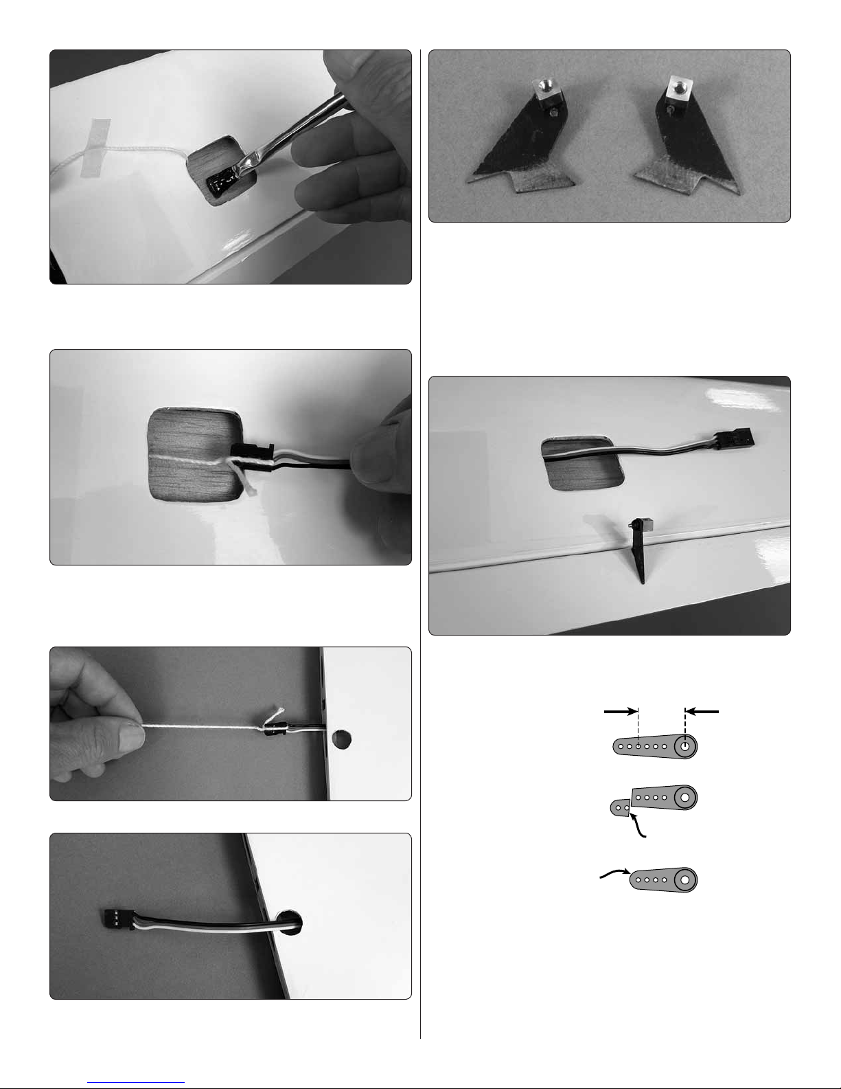
3. Tie the string in the wing around the end of the included
❏
aileron servo extension as shown – a small drop of thin CA
will ensure that the knot doesn’t come undone when you are
drawing the servo wire through the wing.
6. Use medium-grit sandpaper to roughen the bottom
❏
portion of the two larger control horns so glue will adhere.
Install a brass screw-lock connector into the top hole of
both horns and secure with a nylon retainer as shown. Be
certain the retainer snaps on securely. If the retainer ts
loose, replace it with another – four spares included.
7. Cut and remove the covering from the bottom of the
❏
aileron over the slots for the horns.
8.
Insert the horn into the aileron as shown (with the screw-
❏
lock body on the outside of the horn toward the tip of the
wing), then use thin CA to securely glue the horn into place.
4. Carefully pull the servo wire out as you pull the string.
❏
5. Guide the servo connector and the wire out the hole in
❏
the bottom of the wing.
9.
Identify a hole in the servo arm that is 7/16" [11mm]
❏
out from the center (this would be the 4th hole out for Tactic
servos), or the next hole closest in. Use a #55 (.052" [1.3mm])
drill to enlarge the hole to t the aileron pushrod. Then, cut
off the rest of the servo arm so it will not interfere with the
servo hatch cover.
10. Connect the aileron servo to the servo extension in
❏
the wing.
6
Page 7

90°
90°
Left Right
11. Connect the other end of the aileron servo extension
❏
wire to the receiver. Turn on the transmitter and power
the receiver with a separate receiver battery (or the ESC
connected to the receiver and your motor battery). With the
servo powered and centered, install the servo arm to the
servo so it will be perpendicular to the case—if necessary,
use the Sub Trims in your transmitter programming to get
the servo arm perpendicular.
14.
Operate the aileron with the radio to make sure everything
❏
operates smoothly. Make any adjustments necessary.
If working on one wing at a time, now would be a good
time to go back and assemble the second wing so both
servos can be glued in at the same time.
12.
Connect the Z-bend end of an aileron pushrod to the
❏
servo arm as shown. Double the excess servo wire beside
itself in a zigzag pattern so it will t in the wing alongside the
servo. Temporarily place the servo in the wing.
13. Connect the pushrod to the screw-lock connector on
❏
the aileron horn with an M2x3 Phillips machine screw.
15. Use Shoe Goo® or similar exible cement to glue the
❏
servo to the top wing skin (or use tape to hold the servo
in place). Allow the glue to dry at least a few hours before
handling the wing and at least overnight before ying.
NOTE: CA may also be used to glue in the servos, but
should the occasion to remove the servo ever arise, it is
likely the servo bay in the wing will be damaged. With Zap
Goo and similar types of rubbery cement it will be easier to
remove the servo without damaging the wing.
7
Page 8

16. After the glue holding the servos to the wing has
❏
dried, turn on the radio to center the servos. Holding the
ailerons centered, connect the pushrods to the screw-lock
connectors with an M2x3 Phillips machine-thread screw
and a drop of threadlocker. Operate the aileron with your
radio to make sure everything moves smoothly. Make any
adjustments necessary. Trim the excess pushrod material.
Install the Servo Covers
1.
Use curved-tip scissors
❏
or any other kind of small
hobby scissors to trim the
hatches down to the at
base lip that will be taped to
the wing.
2.
❏
over the servo. Operate the
ailerons with your radio to
make sure the servo arm
and/or pushrod do not
interfere with the cover. Make
any adjustments necessary.
Position the hatch
2. Make certain you have everything on-hand to glue the
❏
wings together including 30-minute epoxy, a mixing cup, a
mixing stick, an epoxy brush, masking tape and those paper
towel squares and denatured alcohol mentioned earlier in
the manual.
NOTE:
working time to glue the wing halves together, make sure
you have everything ready and work ef ciently so you don’t
run out of working time before the epoxy begins to harden.
Even though 30-minute epoxy provides enough
3. Mount the hatch to the wing with clear tape.
❏
Join the Wing Halves
3. Mix approximately 1/4 oz. of 30-minute epoxy.
❏
Working quickly, pour some epoxy into the spar cavities in
both wings.
4. Coat one end of the joiner and insert it into one of the
❏
wing halves, pushing it in and out several times to thoroughly
coat the entire spar cavity. Remove the joiner and perform
the same procedure for the other wing, but this time leave
the joiner in place.
5. Coat the protruding end of the joiner and both ends of
❏
both wing halves with epoxy. Then, join the wings together
and wipe away excess epoxy.
1. Test- t the wing halves together with the wing joiner
❏
and the nylon alignment dowel. Make any adjustments
necessary for a good t.
6. Use strips of masking tape on the top and bottom
❏
of the wing to tightly pull the wing halves together while
using the paper towel squares dampened with denatured
alcohol to wipe away excess epoxy as you proceed. Allow
the epoxy to fully harden before removing the tape.
8
Page 9

7.
After the epoxy has hardened, carefully peel off the tape.
❏
Any residual masking tape adhesive may be cleaned with
another paper towel square dampened with naphtha (lighter
uid). Areas of covering that may have lifted from removing
the tape should be re-tightened with your covering iron.
Mount the Wing
ASSEMBLE THE FUSELAGE
Install the Fin and Stab
1. Same as was done with the aileron horns, use
❏
sandpaper to roughen both sides of the tabs on the elevator
and rudder horns, then install screw-lock connectors with
retainers as shown.
1. Roughen the remaining nylon dowels with medium-grit
❏
sandpaper. Then, test- t the dowels into the wing leading
edge.
2. Mount the wing to the fuselage with the dowels and
❏
the M3x14 Phillips screws and M3 at washers. Make any
adjustments so the wing ts the fuselage well—if necessary,
it’s okay to clean out the dowel holes in the wing with a 1/8"
[3mm] drill.
3. Remove, then reinstall the dowels with 30-minute epoxy—
❏
if the dowels t into the wing slightly loosely, micro balloons or
similar ller may be mixed in with the epoxy to ll any voids
to assure a secure bond. Working quickly, wipe away residual
epoxy, then reinstall the wing to the fuselage with the wing
bolts. Do not glue the wing to the fuselage. Allow the epoxy to
fully harden before removing the wing.
4.
Remove the wing from the fuselage. Remove any residual
❏
glue that may have seeped out of the wing past the dowels.
9
2. Cut and remove the covering from the horn slots in
❏
the top of the elevator and right side of the rudder. Glue the
horns into position with thin or medium CA.
3. Apply a strip of masking tape to the bottom of the stab
❏
so epoxy from gluing on the vertical stab ( n) will not get
through.
Page 10

4.Check for proper alignment of the n to the stab. Use
❏
30-minute epoxy to glue the n into the stab (if the t is
loose, add micro balloons to the epoxy). Use a small square
to make sure the n is perpendicular to the stab while the
epoxy hardens.
5. After the epoxy has hardened, remove the masking
❏
tape from the bottom of the stab.
A. Tie a small loop in one end of the line.
B. Fold a piece of masking tape over the line near the
other end. Draw a line on the masking tape. The tape will
be slipped along the line to equalize the stab as described
below.
Make a dry run of the stab alignment process using the
pin and string.
6. Mount the wing to the fuselage. Position and hold the
❏
stab on the stab saddle on the fuselage. View the stab and
wing from behind to see if the stab is parallel with the wing.
If necessary, sand the high side of the stab saddle on the
fuselage to get the stab to align with the wing.
Pin-and-String Technique
We use the pin-and-string technique is used for centering
the stab. To do this, you’ll need an approximately 45" [1.2m]
length of non-elastic line such as Sullivan Kevlar® thread or
Kevlar shing line.
7. Center the exposed balsa portion on the bottom of the
❏
stab over the wing saddle. Use a T-pin to hold the front of
the stab to the balsa plug in the stab saddle.
10
Page 11

8.
AA = A
B = B
A
BB
Insert a T-pin into the front of the wing centered between
❏
the two adjoining ribs. Loop the string over the T-pin.
11. Remove the stab. Glue the stab into position with
❏
30-minute epoxy using the pin and string to check alignment
as done in the previous steps. A couple extra T-pins may be
inserted through the stab and into the balsa saddle to tightly
hold everything in position until the epoxy hardens.
12. After the epoxy from the previous step has hardened
❏
and the T-pins removed, any visible pinholes may be
reduced by going over them with your sealing iron.
9. Pull the string back to one end of the stab. Slide the
❏
masking tape along the string until the line is even with the
trailing edge of the stab.
10. Swing the string over to same spot on the other side
❏
of the stab. Adjust the stab and the tape on the string until
the stab is “equalized” and rotationally centered.
13. Use thin or medium CA glue to attach the tail skid.
❏
11
Page 12

Hook Up the Elevator and Rudder
Elevator
9/32" [7mm]
(2
nd
hole in Tactic
servo arm)
Rudder
7/16" [11mm]
(4
th
hole in Tactic
servo arm)
1.
Mount the elevator and rudder servos as shown. (If your
❏
servos do not t, the servo tray may be trimmed as necessary.)
Drill 1/16" [1.5mm] holes for the servo mounting screws and
mount the servos with the screws that came with them.
4. Straighten the pushrod by removing the bend.
❏
5. Prepare and install the other pushrod through the other
❏
slot in the boom the same way – don’t forget to install the
small plastic tube rst!
❏
pushrods. Make a slight bend 2" [50mm] from the back end
of the pushrod.
❏
slots in the boom – the bend in the wire will allow the end of
the wire to poke up through the slot.
2. Slide one of the small, plastic tubes onto one of the
3. Guide the pushrod down through and out one of the
6. Same as was done for the aileron servo arms, enlarge
❏
the holes in the elevator and rudder servo arms with a #55
(.052" [1.3mm]) drill. It may be necessary to trim the servo
arms, but only enough so they don’t interfere with the inside
of the fuselage when the arms are on the servos.
7. Fit the pushrods into the holes in the servo arms
❏
indicated in the previous illustration. Temporarily install the
servo arms to the servos.
12
Page 13

8.
Fit, then glue the top portion of the pushrod brace into
❏
position all the way up against the “lip” around the wing
saddle—it isn’t critical where the brace is located forward
and aft—where it ts best is ne. Make sure the brace doesn't
interfere with the exit holes of the aileron servo leads.
9. Center the plastic tubes in the brace, then add and
❏
glue the bottom portion of the pushrod brace and the tubes
into place.
11. Still with the radio on, hold the rudder and elevator
❏
centered and tighten the pushrods in the screw-lock
connectors with the M2x3 Phillips screws and a drop of
threadlocker on the threads.
We’ll nish radio installation after the motor has
been installed.
Install the Motor
10. Connect the servos to your receiver and power up the
❏
radio with the transmitter. With the servos centered, adjust
the servo arms on the pushrods so they are perpendicular
to the servo arms. Fasten the servo arms to the servos with
the screws that came with them.
1. On the RimFire .10 use a 1.5mm hex driver to loosen
❏
the set screw in the collar and remove the collar. (If ever
using the motor in a reverse con guration in the future, be
certain to reinstall the collar.)
13
Page 14

2. Mount the motor with four M3x6 Phillips screws and a
❏
small drop of threadlocker on the threads.The motor wires
should be oriented along the bottom of the fuselage.
3. Assemble the folding propeller as shown. Fit the
❏
propeller blades into the hub and then install the pins. The
locknuts should be just tight enough so the blades still
rotate freely on the pins.
5.
Temporarily test- t the propeller/spinner assembly and
❏
check the gap between the front of the fuselage and the
spinner back plate. The gap should be approximately 1-2mm.
Whenever removing the propeller assembly in the future,
do not tap or apply pressure to the front of the backplate.
Instead, insert a sheet of hard plastic or wood between
the spinner gap to push the backplate forward—it also
helps to sand a bevel to the edge of the plastic or wood
part so it can be wedged into the gap.
4. Apply a light lm of oil to the colleted propeller shaft
❏
so the spinner back plate will be easier to remove after the
prop nut has been tightened.
6. Bevel the edges of the battery plate to conform to the
❏
fuselage when in position.
14
Page 15

7.
Cut a strip of the rougher, hook side of the included
❏
adhesive-back hook-and-loop strip to a length of 3-3/8"
[85mm] and apply to the top of the battery plate with CA glue.
8. Roughen the bottom of the fuselage in the area of
❏
the battery plate. Then, use medium CA to glue the battery
plate into position so the aft edge will be approximately 1/2"
[13mm] from the former at the wing LE.
A. Cut the motor wires to the desired length – about 1/2"
[13mm] is ne.
B. Strip approximately 1/8" [3mm] of the insulation from
the end of the wires and tin the exposed wire.
C. Cut and remove the shrink tubing from the bullet
connectors on the cut off ESC wires. Then, unsolder the
three bullets from the old wires.
9. Determine whether you will shorten the wires on
❏
your ESC, or leave the ESC wires as-is. The ESC may be
installed as supplied with the long motor wires, but removal
and installation of the battery will be easier without excess
wire in the way. Follow these instructions to shorten the
ESC wires:
D.
Re-solder the bullets to the shortened wires on the ESC.
15
Page 16

E. Cover the bullets with 3/16" [4.8mm] shrink tubing (not
included).
10. Remove the propeller from the motor before
❏
connecting the ESC! Then, connect the ESC to the motor
and your receiver and power up the radio so you can run the
motor. Make sure the motor is turning in the correct direction.
If not, simply swap any two of the wires between the ESC
and the motor.
Final Assembly
11. Mount the ESC to the side of the fuselage with double-
❏
sided foam mounting tape. If necessary, the included liteply wire holder may be glued into position to keep the motor
terminal wires from contacting the motor.
1.
Install the receiver so it will be secure, somewhat
❏
cushioned and so the antennas will be positioned according
to the manufacturer’s instructions. In this Tori, we taped one
of the antennas to the bottom of the fuselage before installing
the receiver, then t the receiver under the pushrod guide
brace with 1/4" RC foam under the receiver. A hole was
drilled in the fuselage side for a plastic guide tube (cut from a
tube from a spray can or similar – not included) for the other
antenna to achieve the 90° separation speci ed for the Tactic
receiver. (Note that the antennas do not have to be outside
the fuselage, but doing it this way was quick and simple.)
2. Trim the softer, “loop” side of the included adhesive-
❏
back hook-and-loop material to t the battery, and then
attach to the battery.
16
Page 17

2. Test- t the battery in place. Make sure it can be
❏
installed so that the discharge and balance leads will not
contact the spinning motor.
PREPARE THE MODEL FOR FLIGHT
Set the Control Throws
CAUTION: The propeller should not yet be installed.
If the propeller is installed on the motor, remove the
propeller while operating the radio to check the throws.
1. Measure and set the control throws according to
❏
the measurements provided below. If necessary, adjust
the throws with the programming in your transmitter and/
or adjusting where the pushrods connect to the servo
arms and/or control horns. NOTE: The control throws are
measured at the widest part of each control surface.
3. Optional: Make a battery strap from the included
❏
hook-and-loop strap material. For typical ying, a battery
strap is not necessary. But if for some reason you have a
battery that does not conform well to the battery mount
plate, or if you plan on ying inverted or aggressively, you
may want to use the battery strap.
These are the recommended control surface throws:
HIGH RATE LOW RATE
Up
ELEVATOR
RUDDER
AILERONS
2. OPTIONAL: Set up spoilerons. Spoilerons are up
❏
de ection of both ailerons to “spoil” lift causing the model
to sink. Spoilerons are not necessary, but can be an aid in
landing (to shorten the approach) or to get out of thermals
more quickly.
To program spoilerons in most radios, the aileron servos will
have to be connected to separate channels in the receiver.
Typically, the channels are mixed in the radio programming,
then another mix introduced to mix both aileron servos to
a switch, dial or slider for extending the spoilerons. Check
your radio to see if it has a dedicated spoiler function.
17
1/2"
[13mm]
25°
Right
1"
[25mm]
28°
Up
5/8"
[16mm]
33°
Down
1/2"
[13mm]
25°
Left
1"
[25mm]
28°
Down
3/8"
[10mm]
19°
Up
5/16"
[8mm]
15°
Right
3/4"
[19mm]
20°
Up
3/8"
[10mm]
19°
Down
5/16"
[8mm]
15°
Left
3/4"
[19mm]
20°
Down
1/4"
[6mm]
13°
Page 18

The degree of spoilerons is not critical and how much is
2-1/2" [63mm]
2-1/2" [63mm]
Recommended starting C.G.
2" [50mm]
2" [50mm]
3" [75mm]
3" [75mm]
Recommended C.G. range
needed is up to your personal taste. About 3/8" [9.5mm] is
a good place to start. If possible, control the spoilerons with
a proportional dial or slider so you can extend the spoilerons
proportionally (instead of using a switch which is all or nothing).
Arm the ESC
Before the motor will rotate, the ESC must be armed rst:
1. To arm the ESC, move the throttle stick to the lowest
position, turn the transmitter on, and wait for the initiation
tones followed by a single beep. Note: The ESC will autocalibrate the low throttle stick position when powered on.
Be sure that throttle stick is at its lowest point when you
plug the ight battery in (or at the highest point for setting
the brake function- see below).
2. Move the throttle stick to full throttle and the ESC will
con rm this position with a double beep.
3. Lower the throttle again and the ESC will con rm this
lowest position with a sequence of four beeps. THE ESC
IS NOW ARMED. Advancing the throttle stick will cause
the motor to rotate. The propeller blades should not be
installed on the motor until you are ready for ight and
you have con rmed the Fail Safe is operating correctly!
Check the C.G.
1. Set the rulers on a Great Planes C.G. machine to 2-1/2"
❏
[63mm], or mark the recommended, starting C.G. location
on the bottom of the wing where shown.
Set the Fail Safe and the Motor Brake
FAIL SAFE: While you have your radio operational and without
the propeller mounted, now would also be a good time to
set and check the Fail Safe function of your transmitter. Refer
to the instructions that came with your radio control system
to set Fail Safe on the throttle channel so that, in the event of
loss of signal, the motor will stop. To test the Fail Safe, with
the propeller removed and the radio control system turned on,
advance the throttle slightly (just enough to make the motor
turn) and turn off the transmitter. If the Fail Safe is set correctly,
the motor will stop when the transmitter is turned off.
MOTOR BRAKE: While you still have your radio system
powered up and without the propeller mounted, check
the motor brake.
Advance the throttle stick to run the motor, and then move
the throttle stick down to stop the motor. The motor should
stop abruptly (not coast gradually to a stop). If the motor
does not come to an abrupt stop and the brake in the ESC
is not activated, activate the brake as described below:
A. Disconnect the battery from the ESC so it will not
receive power.
B.
With the transmitter turned on, advance the throttle stick.
C.
Connect the battery to the ESC to power the motor. Listen
for the series of beeps. There will be three single beeps
separated by pauses (for brake OFF), then a series of
three double beeps separated by pauses (for brake ON).
To turn the brake ON, lower the throttle during the series
of double beeps. If you wish to turn the brake OFF, lower
the throttle during the three single beeps. Now the brake
is set to the desired function and you may disconnect
the battery and turn off the transmitter.
NOTE: The recommended C.G. range is from 2" to 3"
[50mm - 75mm] back from the leading edge of the wing
approximately where it meets the fuselage. As long as the
Tori is balanced within this range it will y and respond well.
Balanced nearer the front end of the C.G. range the Tori will
be more stable and penetrate wind a little better. Balanced
nearer the aft end of the C.G. range the Tori will “ oat” and
respond to lifting air a little better.
2. Mount the wing to the fuselage and install the propeller
❏
assembly, battery, and the canopy. Do not connect the
battery at this time.
3. At this point the Tori should be completely ready to y.
❏
Check the C.G. by placing the model on the C.G. machine,
18
Page 19

or lift at the lines you marked indicating the recommended,
starting C.G. Depending on the battery you are using, there
should be a little leeway to shift the battery forward or aft
to change the C.G. so it balances at the recommended
starting C.G.
4. Once the location of the battery has been determined,
❏
make a mental note of this location, or mark the inside of the
fuselage or the battery tray to position the battery here for
the proper C.G. when ying the model.
Balance the Model Laterally
WARNING: For brushless electric motors, never have the
motor battery connected to the ESC without the transmitter
turned on – after each ight (or any time after running the
motor) always disconnect the battery before turning off
the transmitter. And when ready to y (or whenever running
the motor for any reason), always turn on the transmitter
rst before connecting the motor battery.
Also make certain your Fail Safe is programmed
correctly so in the event the receiver ever loses signal
(or, if you inadvertently turn off the transmitter before
disconnecting the battery or vice-versa) the motor will
not turn. Follow the instructions that came with your radio
control system to check and set the Fail Safe.
CAUTION: Never run the motor on the ground for more
than a few seconds. Otherwise, you may overload the
motor, battery or ESC.
Range Check
1. Leaving the tail skid on the work surface, lift the Tori
❏
several times by the propeller shaft to see if one wing drops.
2.
If one wing drops consistently, add weight to the opposite
❏
tip by sticking it to the outside or strategically concealing
it inside the balsa tip. An airplane that has been laterally
balanced will track better in ight and maintain its heading
better during maneuvers when the plane is climbing.
PREFLIGHT
Motor Safety Precautions
Failure to follow these safety precautions may result
in severe injury to yourself and others.
● Use safety glasses when starting or running motors.
● Do not run the motor in an area of loose gravel or sand;
the propeller may throw such material in your face or eyes.
●
Keep your fac e and body as well as all spectator s away from
the plane of rotation of the propeller as you run the motor.
● Keep these items away from the prop: loose clothing, shirt
sleeves, ties, scarfs, long hair or loose objects such as
pencils or screwdrivers that may fall out of shirt or jacket
pockets into the prop.
Don’t forget to perform your usual ground range checks as
written in the instruction manual that came with your radio
system to be certain it is operating correctly.
General Pre ight Information
The RimFire .10 is rated for 30A constant current and 35A
surge current. The included 12x6.5 folding propeller draws
an average maximum (in ight) current of about 29A on a
3S battery and about 23A on a 2S battery, so there is no
danger of overloading the motor and it can be run fullthrottle for extended periods (during massive ascensions
to altitude). With a 3S 1800mAh battery this should provide
approximately three minutes of full-throttle run time and with
a 2S 2200mAh battery about 4-1/2 minutes of full-throttle run
time. On 3S the Tori “specs out” in about twenty seconds.
You may experiment with 2S and 3S batteries to nd the
combination you like best. With lighter 2S batteries the Tori
may not climb as quickly, but it will be lighter and have a
farther aft C.G. for detecting thermals easier.
Either way, it is recommended to use a ight timer to indicate
when to stop running the motor so as not to over-discharge
the battery. In the case of a glider such as the Tori, it is
desirable to link the timer to the throttle stick so only motor
run time—not the total time the model is airborne—will be
counted. Until you know what time to set the timer for, start
with a conservative number: say two-minutes for a 3S setup
and three-minutes for a 2S setup.
19
Page 20

When the timer sounds, land. Use a LiPo battery checker
to measure the resting (unloaded) voltage after you land.
Each cell in the pack should not be below 3.7V/cell. When
you charge the battery also note how much capacity it took
to recharge (indicating how much was used for the ight).
Strive to use no more than 80% of the battery’s capacity.
Adjust your timer according to the voltage and capacity
used for the ight.
You can use the worksheet below to determine optimum
ight times based on your ying style and battery capacity.
FLYING
The Tori is not necessarily fragile, but it is a light-weight
motor glider designed for catching thermals, so y it to that
purpose, not as an indestructible, toss-around, foam sport
model. Full throttle ight should be reserved for climbing
to thermal-hunting altitudes only. Be responsible using the
throttle.
Experienced pilots may launch the Tori themselves, but for
the maiden ight, intermediate pilots might want to solicit
the assistance of another pilot to launch the Tori for them. It
may be a good idea to add a few clicks of up elevator trim
so the Tori will be sure to initially climb when released. Once
the Tori is trimmed for straight-and-level ight it will not be
necessary to add up elevator trim.
Typically, the Tori would be launched at full-throttle, but
anything from about half-throttle to full-throttle is ne.
The rst objective will be to get the Tori trimmed. Once trimmed
and at altitude, extend the spoilerons (if programmed) to see
how the Tori behaves. Eventually, you’ll get a feel for when
(and if) to extend the spoilerons so you can land your Tori
right on the spot!
The Tori has no particular ight characteristics that you
need to be made aware of. It’s just an honest- ying, wellmannered oater glider.
Have fun chasing thermals with your Tori!
1
2
3
4
5
6
7
8
A
FORMULAS
Flight Time
(.10 ths )
BCDEFG
Recharge
Capacity
B / A D x .8 E / C
mAh/minute
Battery
Capacity
Target Capacity
to Use in Flight
Recommended
Name
Flight Time
Address
B/1000 / (A/60)
City, State, Zip
Avg. In-Flight
Current
AMA Number
Phone Number
FAA Number
This model belongs to:
 Loading...