

Page 1
Wingspan: 38.5 in [980 mm]
2
Wing Area: 241 in
Wing Loading: 16.7−19.1 oz/ ft
Length: 27 in [685 mm]
[15.5 dm2]
2
[51−58 g/dm2]
Weight: 1.75 − 2 l b
Radio: 4-channel
WARRANTY
Great Planes Model Manufacturing® Co. guarantees this kit to
be free from defects in both material and workmanship at the
date of purchase. This warranty does not cover any component
parts damaged by use or modification. In no case shall Great
Planes’ liability exceed the original cost of the purchased kit.
Further, Great Planes reserves the right to change or modify this
warranty without notice.
In that Great Planes has no control over the final assembly or
material used for final assembly, no liability shall be assumed nor
accepted for any damage resulting from the use by the user of
the final user-assembled product. By the act of using the
user-assembled product, the user accepts all resulting liability.
If the buyer is not prepared to accept the liability associated
with the use of this product, the buyer is advised to return
INSTRUCTION
MANUAL
SPECIFICATIONS
Motor: Included
[790 −910 g]
this kit immediately in new and unused condition to the
place of purchase.
To make a warranty claim send the defective part or item to
Hobby Services at the address below:
Hobby Services
3002 N. Apollo Dr. Suite 1
Champaign IL 61822 USA
Include a letter stating your name, return shipping address, as
much contact information as possible (daytime telephone
number, fax number, e-mail address), a detailed description of
the problem and a photocopy of the purchase receipt. Upon
receipt of the package the problem will be evaluated as quickly
as possible.
READ THROUGH THIS MANUAL BEFORE STARTING CONSTRUCTION. IT CONTAINS IMPORTANT
INSTRUCTIONS AND WARNINGS CONCERNING THE ASSEMBLY AND USE OF THIS MODEL.
Entire Contents © 2011 Hobbico,® Inc. All rights reserved.
Champaign, Illinois
(217) 398-8970, Ext 5
airsupport@greatplanes.com
GPMA6020 v1.1
Page 2
TABLE OF CONTENTS
INTRODUCTION . . . . . . . . . . . . . . . . . . . . . . . . . . . . . . . . 2
Academy of Model Aeronautics . . . . . . . . . . . . . . . . . . 2
SAFETY PRECAUTIONS . . . . . . . . . . . . . . . . . . . . . . . . . 2
DECISIONS YOU MUST MAKE . . . . . . . . . . . . . . . . . . . . 3
Recommended Batteries . . . . . . . . . . . . . . . . . . . . . . . 3
Radio . . . . . . . . . . . . . . . . . . . . . . . . . . . . . . . . . . . . . . 3
Recommended Charger . . . . . . . . . . . . . . . . . . . . . . . 3
Optional Replacement Prop. . . . . . . . . . . . . . . . . . . . . 3
ADDITIONAL ITEMS REQUIRED. . . . . . . . . . . . . . . . . . . 3
Adhesives and Building Supplies. . . . . . . . . . . . . . . . . 3
Optional Supplies and Tools . . . . . . . . . . . . . . . . . . . . 3
KIT INSPECTION . . . . . . . . . . . . . . . . . . . . . . . . . . . . . . . 3
ORDERING REPLACEMENT PARTS . . . . . . . . . . . . . . . 4
KIT CONTENTS. . . . . . . . . . . . . . . . . . . . . . . . . . . . . . . . . 4
HORIZONTAL STABILIZER INSTALLATION . . . . . . . . . 5
INSTALL THE MAIN LANDING GEAR. . . . . . . . . . . . . . . 6
RADIO SETUP. . . . . . . . . . . . . . . . . . . . . . . . . . . . . . . . . . 6
INSTALLATION OF THE FLYING WIRES . . . . . . . . . . . . 9
INTRODUCTION
Originally built by the Granville Brothers Aircraft of Springfi eld,
Massachusetts in 1932, the Gee Bee R1 won the Thompson
Trophy race that same year. It also set a new landplane world
speed record of 296mph (476 km/h) in the Shell Speed Dash.
But, the Gee Bee R1 quickly gained a reputation for being
diffi cult to fl y and dangerous. The Great Planes Gee Bee
EP Rx-R has been designed to eliminate the dangerous
fl ight characteristics, creating an easy to fl y, great looking,
sport plane.
For the latest technical updates or manual corrections to the
Gee Bee EP Rx-R visit the Great Planes web site at www.
greatplanes.com. Open the “Airplanes” link, then select the
Gee Bee EP Rx-R. If there is new technical information or
changes to this model a “tech notice” box will appear in the
upper left corner of the page.
BALANCE THE MODEL (C.G.) . . . . . . . . . . . . . . . . . . . 10
Balance the Model Laterally . . . . . . . . . . . . . . . . . . . 11
PREFLIGHT . . . . . . . . . . . . . . . . . . . . . . . . . . . . . . . . . . . 12
Identify Your Model . . . . . . . . . . . . . . . . . . . . . . . . . . 12
Charge the Batteries . . . . . . . . . . . . . . . . . . . . . . . . . 12
Balance Propellers. . . . . . . . . . . . . . . . . . . . . . . . . . . 12
Ground Check and Range Check . . . . . . . . . . . . . . . 12
MOTOR & BATTERY SAFETY PRECAUTIONS . . . . . . 12
LITHIUM BATTERY HANDLING & USAGE . . . . . . . . . . 12
AMA SAFETY CODE EXCERPTS . . . . . . . . . . . . . . . . . 13
General . . . . . . . . . . . . . . . . . . . . . . . . . . . . . . . . . . . 13
Radio Control . . . . . . . . . . . . . . . . . . . . . . . . . . . . . . . 13
CHECK LIST . . . . . . . . . . . . . . . . . . . . . . . . . . . . . . . . . . 13
FLYING. . . . . . . . . . . . . . . . . . . . . . . . . . . . . . . . . . . . . . . 14
Takeoff . . . . . . . . . . . . . . . . . . . . . . . . . . . . . . . . . . . . 14
Flight . . . . . . . . . . . . . . . . . . . . . . . . . . . . . . . . . . . . . 14
Landing . . . . . . . . . . . . . . . . . . . . . . . . . . . . . . . . . . . 14
SAFETY PRECAUTIONS
Protect Your Model, Yourself & Others…
Follow These Important Safety Precautions
1. Your Gee Bee EP Rx-R should not be considered a toy,
but rather a sophisticated, working model that functions very
much like a full-size airplane. Because of its performance
capabilities, the Gee Bee Rx-R, if not assembled and operated
correctly, could possibly cause injury to yourself or spectators
and damage to property.
2. You must assemble the model according to the instructions.
Do not alter or modify the model, as doing so may result in an
unsafe or unfl yable model. In a few cases the instructions may
differ slightly from the photos. In those instances the written
instructions should be considered as correct.
3. You must take time to build straight, true and strong.
Academy of Model Aeronautics
If you are not already a member of the AMA, please join! The
AMA is the governing body of model aviation and membership
provides liability insurance coverage, protects modelers’ rights
and interests and is required to fl y at most R/C sites.
Academy of Model Aeronautics
5151 East Memorial Drive
Muncie, IN 47302-9252
Tele. (800) 435-9262
Fax (765) 741-0057
Or via the Internet at: http://www.modelaircraft.org
IMPORTANT!!! Two of the most important things you can
do to preserve the radio controlled aircraft hobby are to avoid
fl ying near full-scale aircraft and avoid fl ying near or over
groups of people.
4. You must use an R/C radio system that is in good condition
and other components as specifi ed in this instruction manual.
All components must be correctly installed so that the model
operates correctly on the ground and in the air. You must
check the operation of the model and all components before
every fl ight.
5. If you are not an experienced pilot or have not fl own this type
of model before, we recommend that you get the assistance
of an experienced pilot in your R/C club for your fi rst fl ights.
If you’re not a member of a club, your local hobby shop has
information about clubs in your area whose membership
includes experienced pilots.
6. While this kit has been fl ight tested to exceed normal
use, if the plane will be used for extremely high stress fl ying,
such as racing, or if a motor is used that is stronger than the
one included, the modeler is responsible for taking steps to
reinforce the high stress points and/or substituting hardware
more suitable for the increased stress.
2
Page 3

We, as the kit manufacturer, provide you with a top quality,
thoroughly tested kit and instructions, but ultimately the
quality and fl yability of your fi nished model depends
on how you build it; therefore, we cannot in any way
guarantee the performance of your completed model,
and no representations are expressed or implied as to the
performance or safety of your completed model.
Remember: Take your time and follow the instructions to
end up with a well-built model that is straight and true.
The ElectriFly Equinox™ is a cell balancer that may be used
with any LiPo charger and is capable of maintaining the cell
balance of the battery pack. Note: the AC/DC Triton2 EQ does
not require a cell balancer.
❍ Great Planes ElectriFly Equinox LiPo Cell Balancer
(GPMM3160)
Optional Replacement Prop
❍ APC 10 7 Thin Electric Propeller (APCQ4123)
DECISIONS YOU MUST MAKE
This is a partial list of items required to fi nish the Gee Bee
EP Rx-R that may require planning or decision making before
starting to build. Order numbers are provided in parentheses.
Recommended Batteries
A 2200mAh 11.1V LiPo battery pack is recommended.
❍ Great Planes ElectriFly® LiPo 11.1V 2200mAh 25C
(GPMP0520)
OR
❍ FlightPower® EON-X™ 30 LiPo 11.1V 2200mAh 30C
(FPWP6198)
Radio
The Gee Bee EP Rx-R requires a 4-channel transmitter and
receiver.
Recommended Charger
ADDITIONAL ITEMS REQUIRED
Adhesives and Building Supplies
This is the list of Adhesives and Building Supplies that are
required to fi nish the Gee Bee EP Rx-R.
❍ Phillips Head Screw Driver
❍ Flat Blade Screw Driver
❍ Crescent Wrench
❍ Great Planes Pro CA+ Medium (GPMR6007)
❍ Great Planes CA Activator Foam Safe 2oz. Pump
(GPMR6035)
Optional Supplies and Tools
Here is a list of optional tools mentioned in the manual that
will help you build the Gee Bee EP Rx-R.
❍ CG Machine (GPMR2400)
● Photos and sketches are placed before the step they refer
to. Frequently you can study photos in following steps to
get another view of the same parts.
A LiPo compatible charger is required to charge LiPo batteries.
The Great Planes ElectriFly PolyCharge4™ is designed for
LiPo battery packs only; however, it is able to charge four LiPo
battery packs simultaneously. The ElectriFly Triton2™ and the
AC/DC Triton2 EQ chargers will only charge one pack at a
time, but are capable of charging NiCd, NiMH, Pb acid and
LiPo batteries.
❍ Great Planes PolyCharge4 DC-Only 4 Output LiPo
Charger (GPMM3015)
OR
❍ Great Planes ElectriFly Triton2 DC Computer Peak
Charger (GPMM3153)
OR
❍ Great Planes AC/DC Triton2 EQ Charger/Balancer
(GPMM3156)
Thoughout the life of a LiPo battery, the individual cells located
inside the battery pack may become unbalanced. These
unbalanced cells can shorten the life of the battery or cause
it to malfunction. For this reason, it is always recommended
that a cell balancer be used when charging LiPo batteries.
● The stabilizer and wing incidences and motor thrust angles
have been factory-built into this model. However, some
technically-minded modelers may wish to check these
measurements anyway. To view this information visit the web
site at www.greatplanes.com and click on “Technical Data.”
Due to manufacturing tolerances which will have little or no
effect on the way your model will fl y, please expect slight
deviations between your model and the published values.
KIT INSPECTION
Before starting to build, inspect the parts to make sure
they are of acceptable quality. If any parts are missing or
are not of acceptable quality, or if you need assistance
with assembly, contact Product Support. When reporting
defective or missing parts, use the part names exactly as
they are written in the manual.
Great Planes Product Support
3002 N Apollo Drive, Suite 1 Ph: (217) 398-8970, ext. 5
Champaign, IL 61822 Fax: (217) 398-7721
E-mail: airsupport@greatplanes.com
3
Page 4
ORDERING REPLACEMENT PARTS
Replacement parts for the Great Planes Gee Bee EP Rx-R
are available using the order numbers in the Replacement
Parts List that follows. The fastest, most economical service
can be provided by your hobby dealer or mail-order company.
To locate a hobby dealer, visit the Great Planes web site at
www.greatplanes.com. Select “Where to Buy” in the menu
across the top of the page and follow the instructions provided
to locate a U.S., Canadian or International dealer.
Parts may also be ordered directly from Hobby Services by
calling (217) 398-0007, or via facsimile at (217) 398-7721, but
full retail prices and shipping and handling charges will apply.
Illinois and Nevada residents will also be charged sales tax. If
ordering via fax, include a Visa® or MasterCard® number and
expiration date for payment.
Mail parts orders Hobby Services
and payments by 3002 N Apollo Drive, Suite 1
personal check to: Champaign IL 61822
Be certain to specify the order number exactly as listed in the
Replacement Parts List. Payment by credit card or personal
check only; no C.O.D.
If additional assistance is required for any reason contact
Product Support by e-mail at productsupport@greatplanes.
com, or by telephone at (217) 398-8970.
REPLACEMENT PARTS LIST
Order No. Description
GPMA3170
GPMA3171
GPMA3172
GPMA3173
GPMA3174
GPMA3175
GPMA3176
GPMA3177
GPMA3178
GPMA3179
GPMM1830
GPMG2005
GPMM5500
Fuselage
Wing
Tail Set
Cowl
Wheelpants
Landing Gear Set
Spinner Hub
Propeller
Hatch
Wing Bolt 2 pcs.
GP Silver Series 35A Brushless ESC 5V/2A BEC
Brushless Motor 35mm 1000kV
Servo 9G Micro
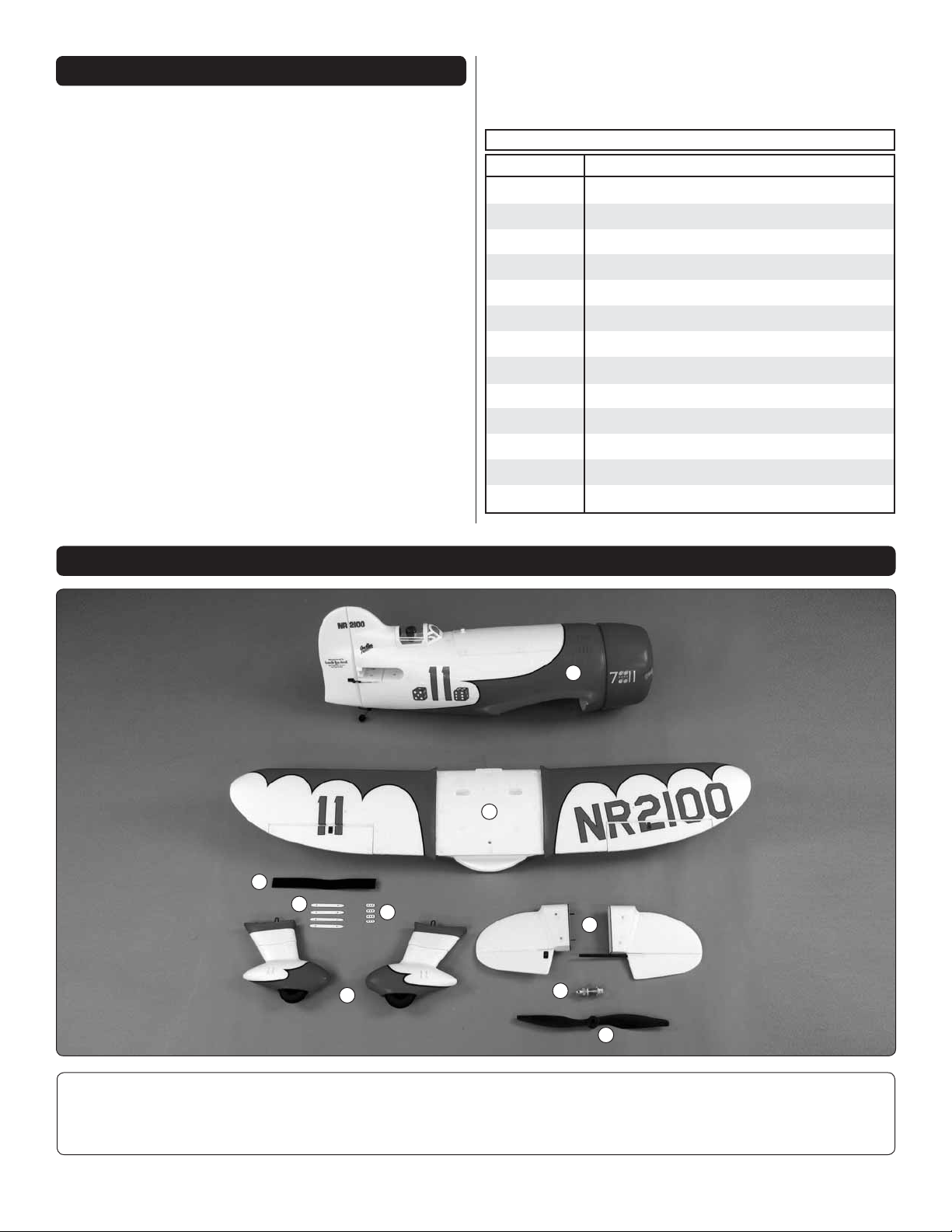
KIT CONTENTS
1
2
5
7
6
4
3
8
1. Fuselage
2. Wing
3. Stabilizer
4. Main Landing Gear and Covers
5. Battery Strap
6. Flying Wire Retainer
4
9
7. Spreader Bar
8. Collet Type Prop Adapter
9. Propeller
Page 5
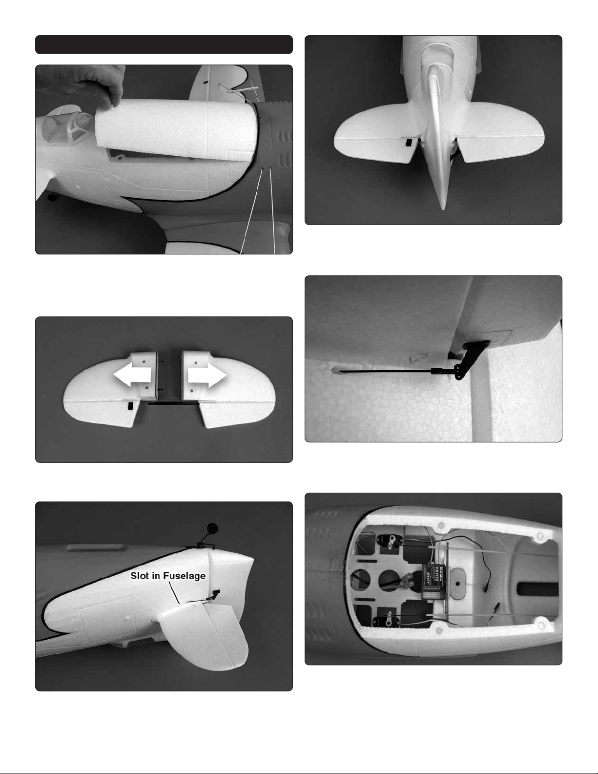
HORIZONTAL STABILIZER INSTALLATION
IMPORTANT: To remove the battery hatch cover, pull straight
up on the knob at the aft end of the hatch cover. The magnets
hold the hatch on well. It does require some force to lift the
hatch.
3. Carefully insert the left stabilizer into the fuselage. Align
❏
the elevator joiner with the hole in the elevator. Center the
horizontal stabilizer in the fuselage.
1. Separate the two stabilizer halves by carefully pulling
❏
them apart.
2. Insert the right stabilizer half into the fuselage. Note that
❏
the bottom of the stabilizer keys into the slot in the bottom
of the opening.
4. Unclip the Faslink from the elevator pushrod. Insert the
❏
elevator pushrod in the middle hole of the elevator control
horn and reinstall the Faslink.
5. Attach a piece of double-sided tape to the back of your
❏
receiver. Remove the backing from the tape and attach the
receiver to the top of the battery tray.
6. Plug the rudder and elevator servos and the ESC into
❏
the receiver.
5
Page 6

INSTALL THE MAIN LANDING GEAR
1. Set the right main landing gear wire in the plastic
❏ ❏
landing gear mount, in the wing. The two slots in the wheel
pant go towards the wing tip.
4. Re-install the outside wheel pant half.
❏ ❏
5. Return to step 1 and install the left main gear.
❏
RADIO SETUP
2. For better access to the main landing gear wire,
❏ ❏
carefully remove the outside of the wheel pant. The wheel
pants are held together with magnets.
3. Press the main landing gear wire into the landing
❏ ❏
gear mounts.
1. Cut three pieces of the rough side of the hook and loop
❏
material ½" [13mm] long. Attach each piece to the top of the
battery tray between the lightening holes.
2. Insert the hook and loop battery strap through the slots
❏
at the front of the battery hatch opening.
6
Page 7

3. Apply the soft side of the hook and loop material to the
FULL
THROTTLE
RUDDER
MOVES
RIGHT
ELEVATOR
MOVES DOWN
RIGHT AILERON
MOVES UP
LEFT AILERON
MOVES DOWN
4-CHANNEL RADIO SETUP
(STANDARD MODE 2)
❏
bottom of the motor battery. Insert the battery in the fuselage
and secure it with the battery strap.
4. Install the wing and secure it with the nylon 560 mm
❏
wing bolt.
5. Plug the aileron servos Y-harness into the receiver.
❏
CAUTION: Perform the follow steps without the propeller
installed.
6. Switch on your transmitter and then connect the motor
❏
battery to the ESC.
7. Adjust the trims on the transmitter so that they are
❏
centered. Center the elevator and rudder and tighten the
screws in the brass screw lock connectors.
8. Check that all the control surfaces move in the correct
❏
direction. If not, reverse the controls on the transmitter.
9. Check that the motor is rotating in the correct direction
❏
(counterclockwise when viewed from the front). If it is not,
remove the cowl and switch two of the three motor wires.
10. Use a box or something similar to prop up the bottom
❏
of the fuselage so the horizontal stabilizer and wing are level.
7
Page 8

Measure the high rate elevator throw fi rst…
These are the recommended control surface throws:
11. Hold a ruler vertically on your workbench against the
❏
widest part (front to back) of the trailing edge of the elevator.
Note the measurement on the ruler.
LOW RATE
Up
3/16"
[5mm] 6°
ELEVATORRUDDERAILERONS
Right
1/2"
[13mm] 10°
Up
1/2"
[13mm] 14°
If your radio does not have dual rates, we recommend setting
the throws at the low rate settings.
NOTE: The throws are measured at the widest part of the
elevators, rudder and ailerons.
To ensure a successful fi rst fl ight, set up your Gee Bee
EP Rx-R according to the control throws specifi ed in this
manual. The throws have been determined through actual
fl ight testing and accurate record-keeping, allowing the
model to perform in the manner in which it was intended.
After you have become accustomed to the way the Gee Bee
EP Rx-R fl ies, you can adjust the amount of control throw
to match your fl ying style. However, too much control throw
could make the model too responsive and diffi cult to control,
so remember, “more is not always better.”
Down
3/16"
[5mm] 6°
Left
1/2"
[13mm] 10°
Down
1/2"
[13mm] 14°
HIGH RATE
Up
3/8"
[10mm] 12°
Right
3/4"
[19mm] 15°
Up
3/4"
[19mm] 21°
Down
3/8"
[10mm] 12°
Left
3/4"
[19mm] 15°
Down
3/4"
[19mm] 21°
12. Move the elevator up with your transmitter and move
❏
the ruler forward so it will remain contacting the trailing edge.
The distance the elevator moves up from center is the “up”
elevator throw. Measure the down elevator throw the same way.
13. Depending on your radio, you may have to adjust the
❏
mechanical position of the pushrod linkage in order to achieve
the proper throw. This is preferred to adjusting AFR, ATV or
servo end points in the transmitter because it preserves the
control resolution of the servo and allows for better control
of the model.
8
Page 9

INSTALLATION OF THE FLYING WIRES
(Optional)
1. Insert the elastic thread through the forward hole in
❏ ❏
the right wing and through the forward hole in the right outer
wheel pant.
3. Reattach the outer wheel pant to the inner wheel pant.
❏ ❏
Extend the elastic thread to the fuselage. Do not stretch the
elastic. Cut the elastic thread, allowing a few inches extra for
securing the thread inside the fuselage.
2. Apply a drop of medium CA to the end of the elastic
❏ ❏
thread and pull the thread into the wheel pant so that the end
of the thread is fl ush with the inside of the wheel pant. Wipe
off any excess CA and spray the CA with Activator.
4. Remove the thread from the wing and insert the elastic
❏ ❏
thread through the forward hole of the spreader bar, through
the wing and through a second spreader bar. The forward end
of the spreader bar is the more rounded end.
5. Insert the elastic thread in the forward hole of the
❏ ❏
fuselage.
9
Page 10

6. Pull the elastic thread through the fuselage. Pass the
❏ ❏
thread through the fl ying wire retainer as shown.
7. Follow the same procedure to install the aft fl ying wire.
❏ ❏
12. Glue the elastic thread to the wheel pant as before.
❏
13. Cut the elastic thread a little long at the other wheel
❏
pant. Pass the thread through the wheel pant so that a slight
amount of tension is on the thread. Apply a drop of CA to the
thread. After the CA has hardened, trim the thread fl ush with
the inside of the wheel pant.
8. Adjust the tension on the fl ying wires so that there
❏ ❏
is no slack in the elastic thread. But, they need to be able to
stretch if hit.
9. Position the spreader bars so that the fl ying wires are
❏ ❏
straight. Apply a drop of CA on the joint between the spreader
bars and the fl ying wires to hold the spreader bars in place.
10. Return to step 1 and install the fl ying wires through
❏
the left wing.
BALANCE THE MODEL (C.G.)
CAUTION: Disconnect the motor battery and switch the
transmitter off.
1. Slide the aluminum collet type prop adapter on the
❏
motor shaft.
11. Pass the elastic thread through the two holes in the
❏
belly pan and through the hole in one of the inside wheel pants.
10
Page 11

2. Install the propeller on the prop adapter and secure it
❏
with the prop washer and prop nut. Slowly rotate the propeller
by hand to check that it does not hit the cowl. If it does, loosen
the prop nut and slide the prop adapter forward slightly.
More than any other factor, the C.G. (center of gravity/
balance point) can have the greatest effect on how a model
fl ies and could determine whether or not your fi rst fl ight will
be successful. If you value your model and wish to enjoy it for
many fl ights, DO NOT OVERLOOK THIS IMPORTANT
PROCEDURE. A model that is not properly balanced may
be unstable and possibly unfl yable.
At this stage the model should be in ready-to-fl y condition with
all of the components in place, including the motor battery.
This is where your model should balance for the fi rst
fl ights. Later, you may experiment by shifting the C.G. 5/32”
[4 mm] forward or 5/32” [4 mm] back to change the fl ying
characteristics. Moving the C.G. forward will improve the
smoothness and stability, but the model will then be less
aerobatic (which may be fi ne for less-experienced pilots).
Moving the C.G. aft makes the model more maneuverable
and aerobatic for experienced pilots. In any case, start at
the recommended balance point and do not at any time
balance the model outside the specifi ed range.
2. With the wing attached to the fuselage, all parts of the
❏
model installed (ready to fl y) and the motor battery installed,
place the model upside-down on a Great Planes CG Machine,
or lift it upside-down at the balance point you marked.
1. If using a Great Planes C.G. Machine™, set the rulers to
❏
1-1/4" [32 mm]. If not using a C.G. Machine, use a fi ne-point
felt tip pen to place a small dot on the top of the wing on both
sides of the fuselage 1-1/4" [32 mm] back from the leading
edge. Due to the Gee Bee having a short nose (and depending
on the battery used), additional nose weight may be required.
3. If the tail drops, the model is “tail heavy.” If possible, move
❏
the motor battery forward to get the model to balance. If the
nose drops, the model is “nose heavy.” If possible, move the
motor battery aft. If moving the motor battery is not enough,
use Great Planes “stick-on” lead (GPMQ4485). To fi nd out
how much weight is required, place incrementally increasing
amounts of weight on the bottom of the fuselage over the
location where it would be mounted inside until the model
balances. A good place to add stick-on nose weight is to the
motor box. Do not attach weight to the cowl—the magnets
securing the cowl cannot support the additional weight. Once
you have determined the amount of weight required, it can
be permanently attached.
4. IMPORTANT: If you found it necessary to add any
❏
weight, recheck the C.G. after the weight has been installed.
Balance the Model Laterally
1. With the wing level, have an assistant help you lift the
❏
model by the engine propeller shaft and the bottom of the
fuse under the TE of the fi n. Do this several times.
2. If one wing always drops when you lift the model, it means
❏
that side is heavy. Balance the airplane by adding weight to the
other wing tip. An airplane that has been laterally balanced
will track better in loops and other maneuvers.
11
Page 12

PREFLIGHT
Ground Check and Range Check
Identify Your Model
No matter if you fl y at an AMA sanctioned R/C club site or if
you fl y somewhere on your own, you should always have your
name, address, telephone number and AMA number on or
inside your model. It is required at all AMA R/C club fl ying sites
and AMA sanctioned fl ying events. Fill out the identifi cation
tag on page 15 and place it on or inside your model.
Charge the Batteries
Follow the battery charging instructions that came with your
radio control system to charge the batteries. You should always
charge your transmitter batteries the night before you go fl ying,
and at other times as recommended by the radio manufacturer.
CAUTION: Unless the instructions that came with your
radio system state differently, the initial charge on new
transmitter should be done for 15 hours using the slow-
charger that came with the radio system. This will
“condition” the batteries so that the next charge may be done
using the fast-charger of your choice. If the initial charge is
done with a fast-charger the batteries may not reach their
full capacity and you may be fl ying with batteries that are
only partially charged.
Always ground check the operational range of your radio
before the fi rst fl ight of the day following the manufacturer’s
instructions that came with your radio. This should be done
once with the motor off and once with the motor running at
various speeds. If the control surfaces do not respond correctly,
do not fl y! Find and correct the problem fi rst. Look for loose
servo connections or broken wires, corroded wires on old
servo connectors, poor solder joints in your battery pack or a
defective cell, or a damaged receiver crystal from a previous
crash. Make sure the receiver antennas are positioned as
recommended in the radio instructions.
MOTOR & BATTERY SAFETY PRECAUTIONS
Failure to follow these safety precautions may result
in severe injury to yourself and others.
Do not run the motor in an area of loose gravel or sand; the
propeller may throw such material in your face or eyes.
Keep your face and body as well as all spectators away from
the plane of rotation of the propeller while the motor is running.
Keep these items away from the prop: loose clothing, shirt
sleeves, ties, scarfs, long hair or loose objects such as pencils
or screwdrivers that may fall out of shirt or jacket pockets into
the prop.
Balance Propellers
Carefully balance your propeller and spare propellers before
you fl y. An unbalanced prop can be the single most signifi cant
cause of vibration that can damage your model. Not only
will motor mounting screws and bolts loosen, possibly with
disastrous effect, but vibration may also damage your radio
receiver and battery.
We use a Top Flite Precision Magnetic Prop Balancer
(TOPQ5700) in the workshop and keep a Great Planes
Fingertip Prop Balancer (GPMQ5000) in our fl ight box.
The motor gets hot! Do not touch it right after operation.
Once the motor battery is connected to the ESC, stay clear
of the propeller. The motor could start at any time.
LITHIUM BATTERY HANDLING & USAGE
WARNING: Read the entire instruction sheet included with
your battery. Failure to follow all instructions could cause
permanent damage to the battery and its surroundings and
cause bodily harm!
ONLY use a LiPo approved charger. NEVER use a
NiCd/NiMH peak charger to charge a LiPo battery.
NEVER charge in excess of 4.20V per cell.
ONLY charge through the “charge” lead. NEVER
charge through the “discharge” lead.
NEVER charge at currents greater than 1C unless
the battery is rated for a higher charge rate.
ALWAYS set the charger’s output volts to match the
battery volts.
ALWAYS charge in a fi reproof location.
NEVER trickle charge.
NEVER allow the battery temperature to exceed 150
degrees F (65 degrees C).
12
Page 13

NEVER disassemble or modify the pack wiring in
any way or puncture the cells.
NEVER discharge below 2.5V per cell.
NEVER place the battery or charger on combustible
materials or leave it unattended during charge or
discharge.
ALWAYS KEEP OUT OF THE REACH OF CHILDREN.
NEVER charge the battery in the plane.
ALWAYS remove the battery from the plane after a
crash. Set it aside in a safe location for at least 20
minutes. If the battery is damaged in the crash it
could catch fi re.
If the battery starts to swell, quickly move the battery to a safe
location, preferably outside. Place it in a bucket, covering the
battery with sand. Never use water to try and put out a LiPo fi re.
other side for spectators. Only personnel involved with fl ying
the aircraft are allowed at or in the front of the fl ight line.
Intentional fl ying behind the fl ight line is prohibited.
4) I will operate my model using only radio control frequencies
currently allowed by the Federal Communications Commission.
5) I will not knowingly operate my model within three miles
of any pre-existing fl ying site except in accordance with
the frequency sharing agreement listed [in the complete
AMA Safety Code].
9) Under no circumstances may a pilot or other person touch
a powered model in fl ight; nor should any part of the model
other than the landing gear, intentionally touch the ground,
except while landing.
CHECK LIST
AMA SAFETY CODE EXCERPTS
Read and abide by the following excerpts from the Academy
of Model Aeronautics Safety Code. For the complete Safety
Code refer to Model Aviation magazine, the AMA web site or
the Code that came with your AMA license.
General
1) I will not fl y my model aircraft in sanctioned events, air shows,
or model fl ying demonstrations until it has been proven to be
airworthy by having been previously, successfully fl ight tested.
2) I will not fl y my model aircraft higher than approximately
400 feet within 3 miles of an airport without notifying the
airport operator. I will give right-of-way and avoid fl ying in the
proximity of full-scale aircraft. Where necessary, an observer
shall be utilized to supervise fl ying to avoid having models fl y
in the proximity of full-scale aircraft.
3) Where established, I will abide by the safety rules for the
fl ying site I use, and I will not willfully and deliberately fl y my
models in a careless, reckless and/or dangerous manner.
5) I will not fl y my model unless it is identifi ed with my name
and address or AMA number, on or in the model. Note: This
does not apply to models while being fl own indoors.
7) I will not operate models with pyrotechnics (any device that
explodes, burns, or propels a projectile of any kind).
Radio Control
During the last few moments of preparation your mind may
be elsewhere anticipating the excitement of the fi rst fl ight.
Because of this, you may be more likely to overlook certain
checks and procedures that should be performed before the
model is fl own. To help avoid this, a check list is provided to
make sure these important areas are not overlooked. Many
are covered in the instruction manual, so where appropriate,
refer to the manual for complete instructions. Be sure to
check the items off as they are completed (that’s why it’s
called a check list!).
1. Check the C.G. according to the measurements provided
❏
in the manual.
2. Be certain the motor battery and receiver are securely
❏
mounted in the fuse with hook and loop material.
3. Balance your model laterally as explained in the
❏
instructions.
4. Use threadlocking compound to secure critical fasteners
❏
such as the screws in the screw-lock pushrod connectors.
5. Add a drop of oil to the axles so the wheels will turn freely.
❏
6. Confi rm that all controls operate in the correct direction
❏
and the throws are set up according to the manual.
7. Make sure any servo wires do not interfere with other
❏
systems (servo arms, pushrods, etc.).
8. Balance your propeller (and spare propellers).
❏
9. Tighten the propeller nut and spinner.
❏
1) I will have completed a successful radio equipment ground
check before the fi rst fl ight of a new or repaired model.
2) I will not fl y my model aircraft in the presence of spectators
until I become a qualified flier, unless assisted by an
experienced helper.
3) At all fl ying sites a straight or curved line(s) must be
established in front of which all fl ying takes place with the
10. Place your name, address, AMA number and telephone
❏
number on or inside your model.
11. If you wish to photograph your model, do so before
❏
your fi rst fl ight.
12. Range check your radio when you get to the fl ying fi eld.
❏
13
Page 14

FLYING
The Gee Bee EP Rx-R is a great-fl ying model that fl ies smoothly
and predictably. The Gee Bee EP Rx-R does not, however,
possess the self-recovery characteristics of a primary R/C
trainer and should be fl own only by experienced R/C pilots.
that you will need to apply more right rudder to counteract
motor torque. Be smooth on the elevator stick, allowing the
model to establish a gentle climb to a safe altitude before
turning into the traffi c pattern.
Flight
CAUTION (THIS APPLIES TO ALL R/C AIRPLANES):
If, while fl ying, you notice an alarming or unusual sound such
as a low-pitched “buzz,” this may indicate control surface
fl utter. Flutter occurs when a control surface (such as an
aileron or elevator) or a fl ying surface (such as a wing or
stab) rapidly vibrates up and down (thus causing the noise).
In extreme cases, if not detected immediately, fl utter can
actually cause the control surface to detach or the fl ying
surface to fail, thus causing loss of control followed by an
impending crash. The best thing to do when fl utter is detected
is to slow the model immediately by reducing power, then
land as soon as safely possible. Identify which surface
fl uttered (so the problem may be resolved) by checking all
the servo grommets for deterioration or signs of vibration.
Make certain all pushrod linkages are secure and free of
play. If it fl uttered once, under similar circumstances it will
probably fl utter again unless the problem is fi xed. Some
things which can cause fl utter are; Excessive hinge gap;
Not mounting control horns solidly; Poor fi t of pushrod in
horn; Side-play of wire pushrods caused by large bends;
Excessive free play in servo gears; Insecure servo mounting;
and one of the most prevalent causes of fl utter; Flying an
over-powered model at excessive speeds.
For reassurance and to keep an eye on other traffi c, it is a
good idea to have an assistant on the fl ight line with you. Tell
him to remind you to throttle back once the plane gets to a
comfortable altitude. While full throttle is usually desirable for
takeoff, most models fl y more smoothly at reduced speeds.
Take it easy with the Gee Bee EP Rx-R for the fi rst few fl ights,
gradually getting acquainted with it as you gain confi dence.
Adjust the trims to maintain straight and level fl ight. The Gee
Bee is a racing style plane but is capable of performing many
basic sport plane maneuvers. After fl ying around for a while,
and while still at a safe altitude with plenty of battery power
remaining, practice slow fl ight and execute practice landing
approaches by reducing the throttle to see how the model
handles at slower speeds. Add power to see how she climbs
as well. Continue to fl y around, executing various maneuvers
and making mental notes (or having your assistant write
them down) of what trim or C.G. changes may be required
to fi ne tune the model so it fl ies the way you like. Mind your
fl ight time, but use this fi rst fl ight to become familiar with your
model before landing.
Landing
Takeoff
Before you get ready to takeoff, see how the model handles
on the ground by doing a few practice runs at low speeds on
the runway. Hold “up” elevator to keep the tail wheel on the
ground. If necessary, adjust the tail wheel so the model will roll
straight down the runway. The Gee Bee is very short coupled
and can require a lot of rudder throw, especially when taking
off in a cross wind. If you need to calm your nerves before
the maiden fl ight, bring the model back into the pits. Top off
the battery and check all fasteners and control linkages for
peace of mind. We recommend setting a timer to limit the
fl ight time and avoid a dead stick landing. Start with the timer
set for 5-minutes. This should allow for a couple of landing
attempts before the power starts to drop off.
Remember to takeoff into the wind. When you’re ready, point
the model straight down the runway, hold a bit of up elevator
to keep the tail on the ground to maintain tail wheel steering,
then gradually advance the throttle. As the model gains
speed decrease up elevator allowing the tail to come off the
ground. One of the most important things to remember with
a tail dragger is to always be ready to apply right rudder to
counteract motor torque. Gain as much speed as your runway
and fl ying site will practically allow before gently applying up
elevator, lifting the model into the air. At this moment it is likely
To initiate a landing approach, lower the throttle while on the
downwind leg. Allow the nose of the model to pitch downward
to gradually bleed off altitude. Continue to lose altitude, but
maintain airspeed by keeping the nose down as you turn onto
the crosswind leg. Make your fi nal turn toward the runway
(into the wind) keeping the nose down to maintain airspeed
and control. The Gee Bee loses speed quickly, so adjust the
throttle to keep the speed up. Level the attitude when the
model reaches the runway threshold, modulating the throttle
as necessary to maintain your glide path and airspeed. If you
are going to overshoot, smoothly advance the throttle (always
ready on the right rudder to counteract torque) and climb
out to make another attempt. When you’re ready to make
your landing fl are and the model is a foot or so off the deck,
smoothly increase up elevator until it gently touches down.
Once the model is on the runway and has lost fl ying speed,
hold up elevator to place the tail on the ground, regaining tail
wheel control.
After the fl ight you can continue to run the motor until the ESC
cut-off stops the motor. This additional time can be added to
the 5-minutes on your timer. Remember to leave enough time
for a couple attempts at landing. You do not want the power to
drop just as you power up to go around for a second landing
attempt.
One fi nal note about fl ying your model. Have a goal or fl ight
plan in mind for every fl ight. This can be learning a new
14
Page 15

maneuver(s), improving a maneuver(s) you already know,
or learning how the model behaves in certain conditions
(such as on high or low rates). This is not necessarily to
improve your skills (though it is never a bad idea!), but more
importantly so you do not surprise yourself by impulsively
attempting a maneuver and suddenly fi nding that you’ve run
out of time, altitude or airspeed. Every maneuver should be
deliberate, not impulsive. For example, if you’re going to do a
loop, check your altitude, mind the wind direction (anticipating
rudder corrections that will be required to maintain heading),
remember to throttle back at the top, and make certain you
are on the desired rates (high/low rates). A fl ight plan greatly
reduces the chances of crashing your model just because
of poor planning and impulsive moves. Remember to think.
Have a ball! But always stay in control
and fl y in a safe manner.
GOOD LUCK AND GREAT FLYING!
This model belongs to:
Name
Address
City, State, Zip
Phone Number
AMA Number
15
Page 16

GPMA6020 v1.1Entire Contents © 2011 Hobbico,® Inc. All rights reserved.
 Loading...