

Page 1
®
:
3
]
2
]
g]
g:
8 oz/f
2
m
2
]
Length:
]
ad
Channe
cro servos
le
ctricMoto
SC:25
A br
ushles
s
Wingspan: 38 in [965mm]
Wingspan
Wing Area: 242 in2 [15.6dm2]
Wing Area:242 in2 [15.6dm
Weight: 23-25 oz [650-710g]
Wing Loading: 13.7-14.8 oz/ft2 [42-45 g/dm2]
Wing Loadin
Length: 28 in [710mm]
Radio: 4-Channel with four micro servos
R
Electric Motor: RimFire™ 400 (28-30-950kV)
E
ESC: 25A brushless
E
Weight:23-25 oz [650-710
8 in [965mm
.7-14.
28 in [710mm
: 4-
r:mFir
t
[42-45 g/d
l with four mi
400 (28-30-950kV)
WARRANTY
ARRAN
Great Planes® Model Manufacturing Co. guarantees this kit to be free from defects in both material and
workmanship at the date of purchase. This warranty does not cover any component parts damaged by use or
modifi cation. In no case shall Great Planes’ liability exceed the original cost of the purchased kit. Further,
Great Planes reserves the right to change or modify this warranty without notice.
In that Great Planes has no control over the fi nal assembly or material used for fi nal assembly, no liability shall be
assumed nor accepted for any damage resulting from the use by the user of the fi nal user-assembled product. By
the act of using the user-assembled product, the user accepts all resulting liability.
If the buyer is not prepared to accept the liability associated with the use of this product, the buyer is
advised to return this kit immediately in new and unused condition to the place of purchase.
To make a warranty claim Hobby Services
send the defective part 3002 N. Apollo Dr., Suite 1
or item to Hobby Services Champaign, IL 61822 USA
at this address: (217) 398-8970 Ext. 5
Include a letter stating your name, return shipping address, as much contact information as possible (daytime
telephone number, fax number, e-mail address), a detailed description of the problem and a photocopy of the
purchase receipt. Upon receipt of the package, the problem will be evaluated as quickly as possible.
READ THROUGH THIS MANUAL BEFORE STARTING CONSTRUCTION. IT CONTAINS IMPORTANT INSTRUCTIONS
AND WARNINGS CONCERNING THE ASSEMBLY AND USE OF THIS MODEL.
Page 2
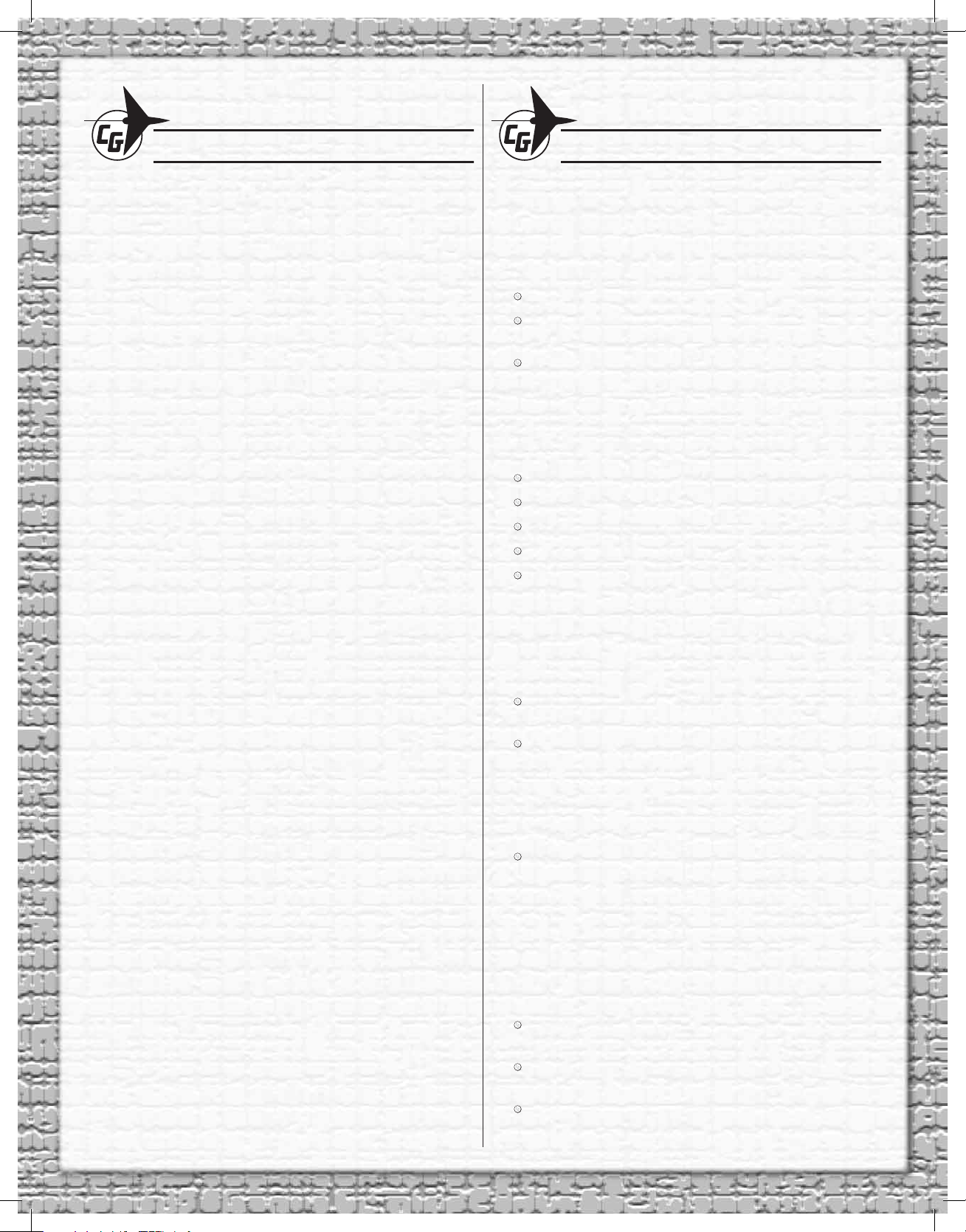
TABLE OF CONTENTS
ADDITIONAL ITEMS REQUIRED
ADDITIONAL ITEMS REQUIRED .....................................2
Radio System .................................................................2
Batteries and Charger ....................................................2
Hardware and Accessories ............................................2
Adhesives & Building Supplies .......................................3
Optional Supplies and Tools ...........................................3
PREPARATION .................................................................. 3
ASSEMBLE THE WINGS ................................................... 4
Join the Ailerons and Mount the Servos ........................4
Hook Up the Ailerons .....................................................5
Join the Wings ................................................................5
Mount the Wheels and Landing Gear .............................6
ASSEMBLE THE FUSELAGE ...........................................7
Glue in the Horizontal Stabilizer (Stab) ..........................7
Hinge the Elevators and Rudder ..................................10
Hook up the Elevator and Rudder ................................11
Mount the Motor and ESC ............................................12
Mount the Battery and Receiver ...................................14
Optional: Install Pilot Figure (Not Included) ..................14
GET THE MODEL READY TO FLY ..................................15
Set the Control Throws .................................................15
Balance and Mount the Propeller .................................16
Apply the Decals ..........................................................16
Balance the Model (C.G.) .............................................16
Balance the Model Laterally .........................................17
FLYING .............................................................................17
Prefl ight ........................................................................17
Takeoff ..........................................................................17
Flight ............................................................................18
Landing ........................................................................18
REPLACEMENT PARTS ..................................................18
RADIO SYSTEM
The Chipmunk 400 ARF requires a four-channel radio with a
small receiver that will fi t into available space in the fuselage
not already occupied by the battery. The following servos
and servo extensions are also recommended:
(4) Futaba® S3114 micro servos (FUTM0414)
(2) Hobbico® Command™ 6" [150mm] extensions
(HCAM2000)
(1) Futaba dual servo extension (FUTM4130)
BATTERIES AND CHARGER
Most 3S (11.1V) LiPo batteries in the 1200mAh – 1500mAh
range should fi t fi ne in the Chipmunk. Following are a few
suitable recommendations:
11.1V ElectriFly 1300mAh 25C (GPMP0505)
11.1V ElectriFly BP 1250mAh 20C (GPMP0715)
11.1V FlightPower® 1200mAh 30C (FPWP6105)
11.1V ElectriFly 1200mAh 30C (GPMP0836)
11.1V ElectriFly 1300mAh 30C (GPMP0840)
Be certain to read and follow all the instructions and
precautions that come with LiPo batteries and chargers.
Charge LiPo batteries only with chargers intended for LiPo
batteries or with chargers that have a LiPo setting. Following
is a suitable charger:
Great Planes PolyCharge4™ DC-only LiPo battery
charger (GPMM3015)
Additionally, one (1) Great Planes ElectriFly
Equinox™ LiPo Cell Balancer w/3S battery adapter
(GPMM3160) for each battery to be charged
simultaneously is recommended. (If you wish to
charge three batteries simultaneously, three Equinox
balancers will be required.)
Finally, if charging the battery from a 120V AC outlet
is preferred (rather than using a 12V battery), a 12
Volt power supply will also be required (Hobbico 12
Volt Power Supply - HCAP0250).
HARDWARE AND ACCESSORIES
Following is the list of additional hardware and accessories
required to fi nish the Chipmunk 400. Order numbers are
provided in parentheses.
Great Planes RimFire 400 (28-30-950kV) out-runner
brushless motor with prop adapter (GPMG4560)
Great Planes Silver Series 25 Amp Brushless
Electronic Speed Controller (GPMM1820)
(1 pkg. of 3) Great Planes 3.5mm male/2mm female
bullet adapters (GPMM3122)
2
Page 3
Great Planes 8x6 Power Flow™ Slo-Flyer Elec Prop
(pkg. of 2, GPMQ6610)
(1 pkg) Great Planes adhesive-back Velcro®
(GPMQ4480)
Double-sided foam mounting tape (GPMQ4440)
Stick-on segmented lead weights (GPMQ4485)
Great Planes 3/8"x3" [10x80mm] heat shrink tubing
(GPMM1060)
ADHESIVES & BUILDING SUPPLIES
In addition to common household and hobby tools, this
is the “short list” of the most important items required to
assemble the Chipmunk 400. Great Planes Pro™ CA glue is
recommended.
Thin CA (1/2 oz. [15g] Thin Pro CA, GPMR6001)
Medium CA (1/2 oz. [15g] Medium Pro CA+,
GPMR6007)
30-minute epoxy (Pro 30-minute epoxy, GPMR6047)
CA applicator tips (HCAR3780)
Threadlocker thread locking cement (GPMR6060)
#11 blades (5-pack, HCAR0211)
#1 Hobby knife (HCAR0105)
The following drill bits were also used: 1/16" [1.6mm],
1/8" [3.2mm], 5/64" [2mm]. For precision, the following
“numbered” drills were also used, but if you cannot
get numbered drills a hobby knife could be used
instead: #57 (.043" [1mm]), #55 (.052" [1.3mm])
PREPARATION
1. Lay three or four
paper towels over each
other and cut the stack
into small squares.
These small paper towel
squares, dampened with
denatured alcohol, will
come in handy for epoxy
cleanup and other general
cleanup during assembly.
OPTIONAL SUPPLIES AND TOOLS
Here is a list of optional items mentioned in the manual that
will help you build the Chipmunk 400.
Williams Brothers 1/8-scale Sportsman pilot
(WBRQ1130)
#2x1/4" [6mm] or #2x1/2" [12mm] screws and #2
washers (for mounting optional pilot)
Hobby paints/paint brushes (for painting pilot)
2 oz. [57g] spray CA activator (GPMR6035) or 4 oz.
[113g] aerosol CA activator (GPMR6034)
CA debonder (GPMR6039)
CG Machine™ (GPMR2400)
Power Point Prop Balancer (TOPQ5700)
A model airplane covering iron with a protective
covering sock may also be necessary to retighten
the covering and remove any wrinkles that may have
formed after the model was originally covered at the
factory. If you don’t already have a covering iron,
the 21st Century® sealing iron (COVR2700) and 21st
Century iron cover (COVR2702) are recommended.
2. Remove the masking tape holding all the control
surfaces to their main parts. If necessary, clean off any
residual tape glue with a couple of your paper towel squares
dampened with naphtha (lighter fl uid).
3. Refer to the separate instruction sheet titled How To
Tighten Covering On ARF Models. Follow the instructions
to tighten the covering. If you prefer to get started on
assembly right away, the tightening process could be done
later (but it is usually easiest to do while the model is still in
separate pieces).
3
Page 4
ASSEMBLE THE WINGS
JOIN THE AILERONS AND MOUNT THE SERVOS
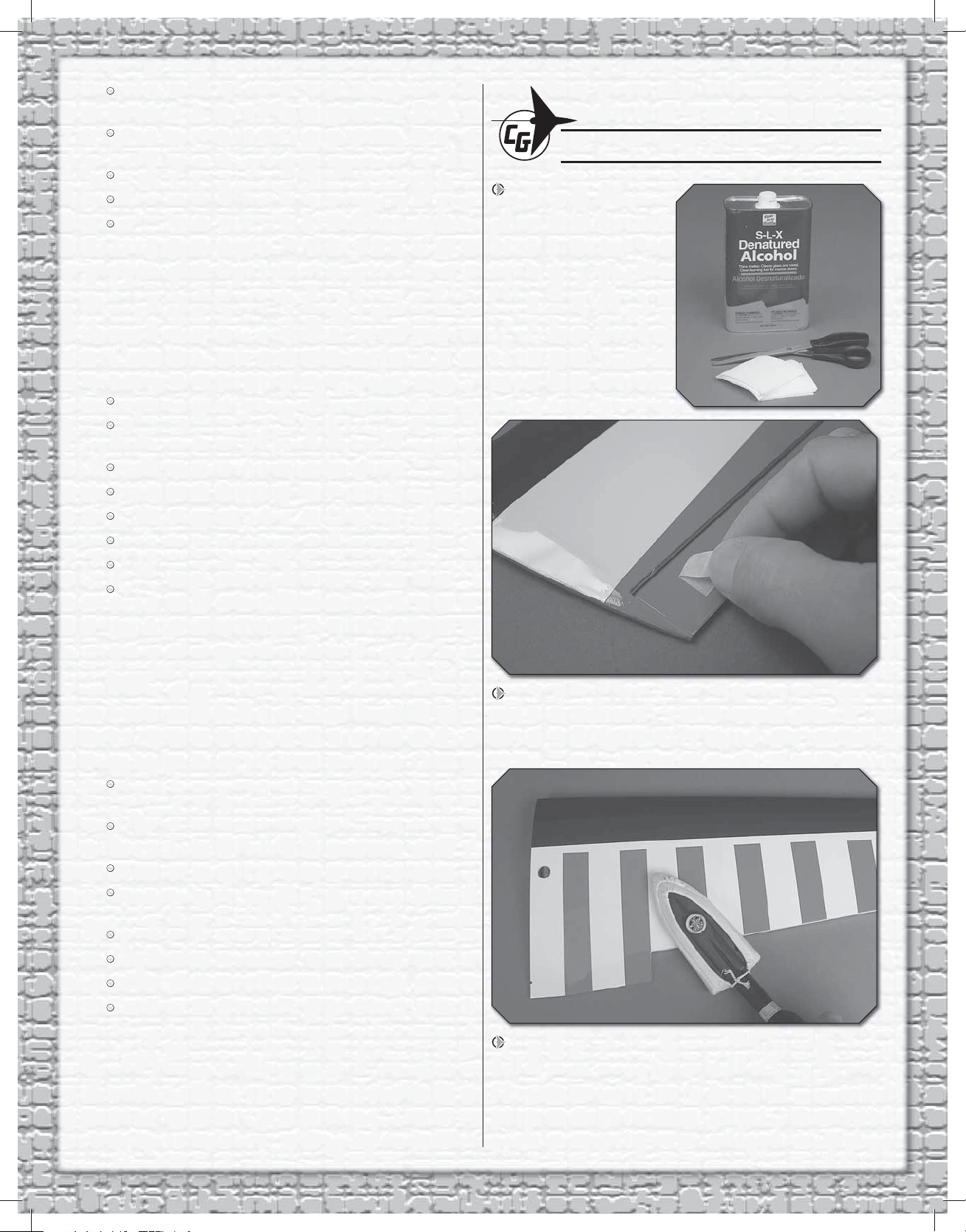
1. Stick a small pin through the middle of three CA hinges.
Insert the hinges up to the pins into the hinge slots in one of
the wings.
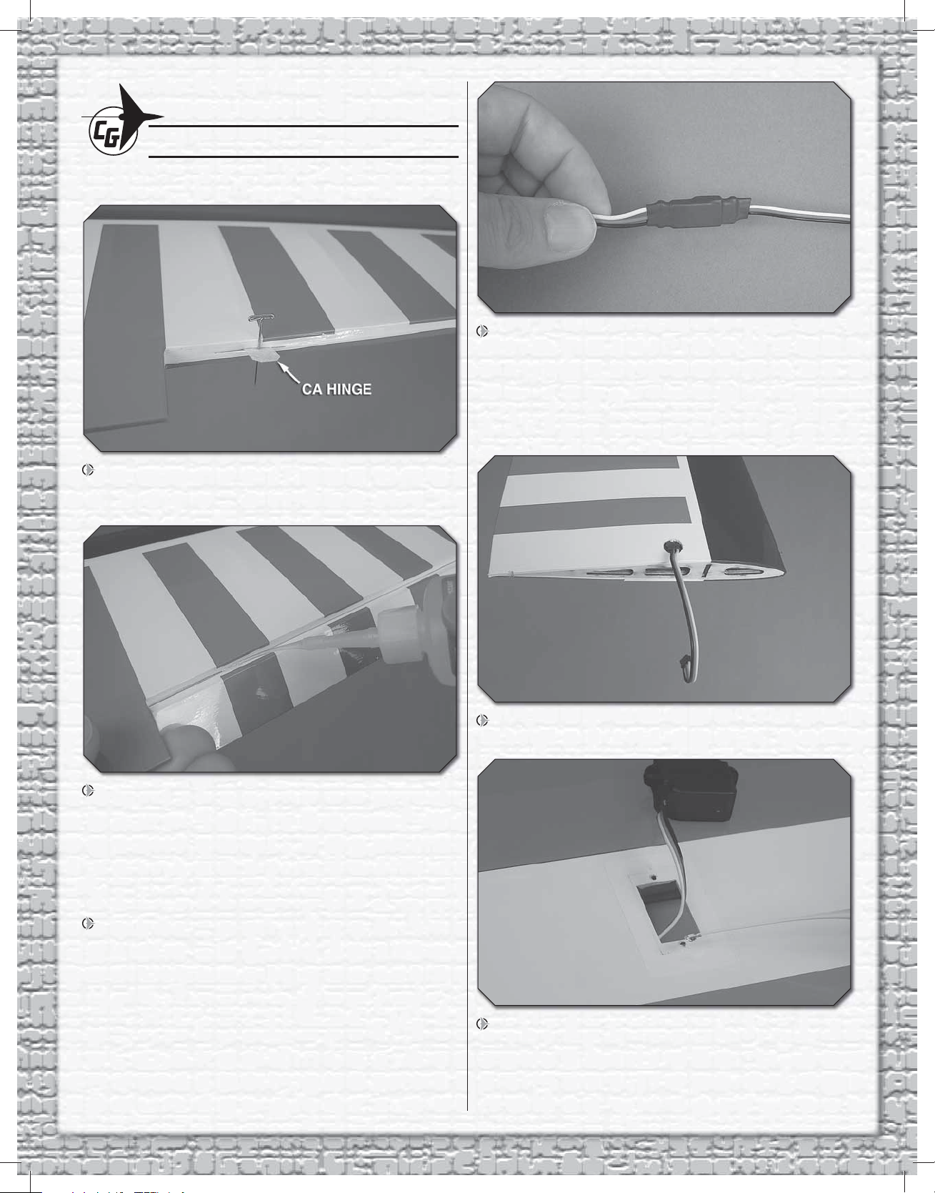
4. Connect a 6" [150mm] servo extension to one of
your aileron servos. Use a piece of Great Planes 3/8" x 3"
[10 x 80mm] heat shrink tubing (GPMM1060, not included)
cut in half (or tape or other suitable clips intended for
this purpose) to secure the servo plugs so they cannot
accidentally become disconnected. Use a hobby torch or a
heat gun to shrink the tubing.
2. Fit the matching aileron to the hinges in the wing and
take out the pins. Make sure there is a small gap between
the leading edge of the aileron and the wing—just enough
to see light through or to slip a piece of paper through. Add
three or four drops of thin CA to the top and bottom of each
hinge, waiting a few seconds between each drop to allow the
CA to wick all the way in.
3. Hinge the other aileron to the other wing the same way.
After the CA has hardened, rapidly move the ailerons up and
down several times to “break in” the hinges so the ailerons
will move more freely.
5. Guide the servo wire down through the ribs and out the
hole in the top of one of the wings.
6. Temporarily mount the servo in the wing with two of the
included 2 x 4mm Phillips wood screws—the screw holes
are predrilled. Remove the screws and take the servo out of
the mount. Add a few drops of thin CA to the screw holes,
allow to harden, and then remount the servo.
4
Page 5
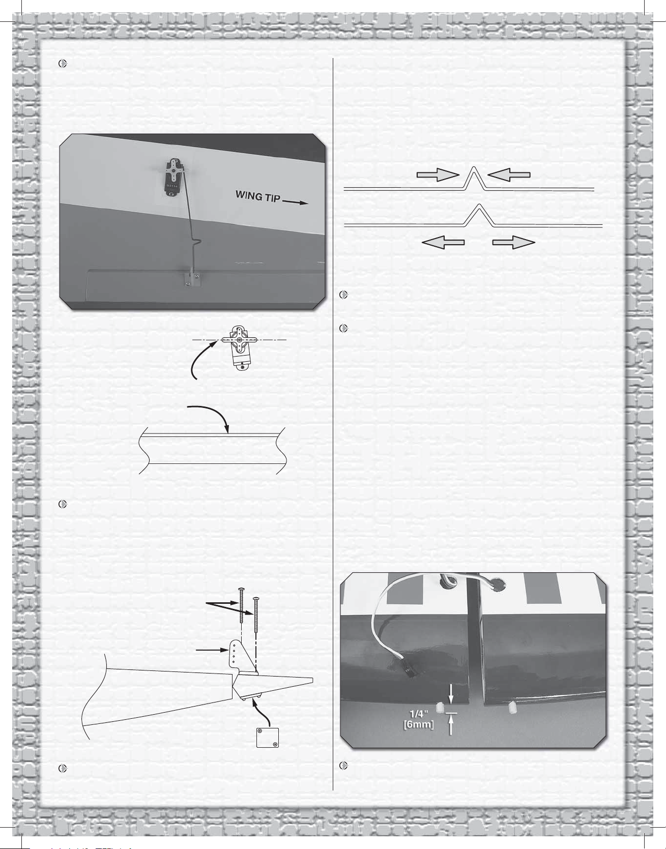
7. Mount your other aileron servo in the other wing the
WING TRAILING EDGE
PARALLEL WITH WING
TRAILING EDGE
HORN MOUNTING PLATE
CONTROL HORN
2x10mm MACHINE THREAD
PHILLIPS SCREWS
ADJUST THE “V” BEND
same way.
HOOK UP THE AILERONS
Refer to this photo while hooking up the ailerons.
the aileron pushrod wire will fi t. Drill 5/64” [2mm] (or 3/32”
[2.4mm]) holes through the aileron for the horn mounting
screws and hook up the aileron as shown—note in the photo
that the horn is located on the aileron so the pushrod will be
perpendicular to the wing trailing edge and the servo arm.
3. Use pliers to adjust the V-bend in the wire so the aileron
will be centered.
4. Hook up the other aileron the same way. Note that the
aileron pushrods are connected to the servo arms nearest
the wing tips. This will allow the ailerons to move in opposition
(as they should).
1. Connect one of the aileron servos in the wing to your
receiver. Turn on the transmitter and hook up a charged
battery and the ESC so you can operate the servo with
the transmitter. With the trims on the transmitter centered,
mount the arm to the servo so it will be parallel (or as close
to parallel as you can reasonably get) with the trailing edge.
2. Enlarge the holes in one of the control horns included
with this kit with a #57 (.043” [1mm]) drill or a hobby knife so
JOIN THE WINGS
1. Use epoxy to glue the wing dowels into each wing with
1/4" [6mm] protruding.
5
Page 6
MOUNT THE WHEELS AND LANDING GEAR
3/32" [2mm]
3/32" [2mm]
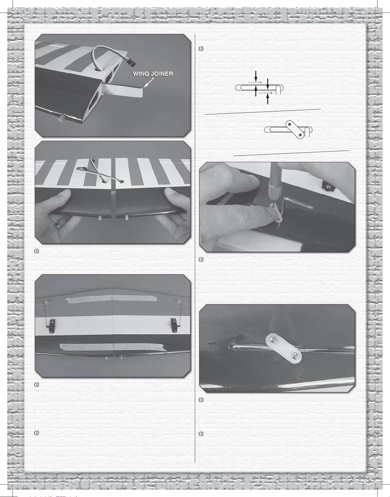
1. Insert the right and left main landing gear wires into
the wing so they will be angled forward.
2. Without using any glue, test fi t the wing halves together
with the plywood wing joiner. Make sure the wings fi t well
with no gap. Make any adjustments necessary for a good fi t.
3. Use 30-minute epoxy to glue the wings together with
the joiner—be certain to coat all mating surfaces—inside
the pockets where the joiner goes, all the way around the
joiner and the ends of both wing halves. Use masking tape to
hold the halves together and wipe away excess epoxy before
it hardens.
2. Holding a fl at landing gear strap over one of the gears
in the wing, drill a 1/16" [1.6mm] hole into the bottom of
the wing using the hole in the strap as a guide—note that
the strap must be mounted at an angle so the holes will be
no farther than 3/32" [2mm] from the wire. Otherwise, the
screws will miss the hardwood rail inside.
3. Mount the strap to the wing with a 2 x 8mm Phillips
wood screw. Holding the strap at an angle so the second
hole will be no farther than 3/32” [2mm] from the front of the
wire, drill the hole and install the second screw.
4. After the epoxy has hardened, carefully peel off the
masking tape. If necessary, use your covering iron to reattach
any lifted covering back down to the balsa underneath.
4. Mount the other strap over the other gear the same way.
Remove all the screws, add a drop of thin CA to each hole,
allow to harden, and then reinstall the straps and screws.
6
Page 7

Now you can mount the wheel pants…
5. Use a hobby knife to chamfer the top of the hole on the
inside of both wheel pants so it will fi t all the way to the wire
gear leg.
1. Use a hobby knife with a sharp blade to cut the covering
from the fuselage over the exit slot for the elevator pushrod
guide tube (located just under the leading edge of the slot
for the horizontal stabilizer) and from the exit slot for the
rudder pushrod guide tube (located just behind and below
the slot for the vertical stabilizer). The stab is shown already
in position, but yours should not yet be in place.
6. Mount the pants and wheels to the landing gears with
a humped mounting strap and two 2 x 4mm Phillips wood
screws in the predrilled holes. Same as has been done all
along, remove the screws, add a drop of thin CA to the screw
holes, allow to harden, and then remount the pants.
ASSEMBLE THE FUSELAGE
GLUE IN THE HORIZONTAL STABILIZER (STAB)
Disregard the elevator and stab in the fi rst two pictures. They
are not actually installed until step 16.
2. Temporarily join the elevators to the horizontal
stabilizer (stab) with two hinges in each side—at this time,
the centering pins aren’t required—they will be used when
permanently installing the hinges later. Make certain there
is a small gap between the ends of the elevators and the
balance tabs on the elevators. Center the elevator joiner
wire on the stab as shown on the previous page. Mark both
elevators at the ends of the wire.
3. Drill a 1/16" [1.6mm] hole into the leading edge of both
elevators at the marks. Use a hobby knife or a 1/16" [1.6mm]
drill to cut grooves in the leading edge of the elevators to
accommodate the joiner wire.
7
Page 8

4. Test fi t the joiner wire and make sure it goes all the way
A A'
A = A'
B = B'
B
B'
into both elevators.
5. Test fi t the elevators to the stab with the joiner wire and
the hinges. Be certain the elevators are parallel with each
other and that the gaps still exist between the ends of the
stab and the elevator balance tabs. If necessary, remove the
wire and bend it so the elevators will be parallel with each
other and lie fl at on your workbench.
7. Once the stab is centered, stick pins into the trailing
edge tightly to both sides of the fuselage, holding the trailing
edge in place.
8. Stick another pin into the top of the front of the
fuselage centered over the stringer. Tie a loop in one end of
an approximately 30" [760mm] length of K+S #801 Kevlar
thread or similar non-elastic line.
6. Separate the elevators from the stab and take out the
hinges. Install the stab into the fuselage. Taking accurate
measurements from side-to-side, center the trailing edge by
equalizing the distance between both ends of the stab and
the fuselage.
9. Wrap a piece of masking tape over the line near the
other end and mark an arrow or a line on it. Slide the tape
8
Page 9

along the string until the arrow aligns with one end of the
stab. Swing the string over to the same spot on the other side
of the stab to see if the distances are equal as shown in the
sketch. Adjust the stab and slide the tape along the string
until the stab is aligned.
10. Once the stab is centered, use a fi ne-point felt-tip pen
to mark the fuselage sides around the top and bottom of
the stab.
ink with a few of your paper towel squares dampened with
denatured alcohol.
13. If necessary, use a 1/8" [3.2mm] drill to clear any
epoxy from the wing bolt hole near the trailing edge of the
wing. Cut the covering from the bottom of the wing around
the wing bolt hole for the plywood wing bolt washer. Glue
the washer into position while simultaneously mounting the
wing to the fuselage with a 3 x 20mm Phillips screw and a
3mm washer. (The wing will be used as a reference for stab
alignment in the following steps.)
11. Remove the stab from the fuselage. Using a soldering
iron with a fi ne tip guided by a metal straightedge, cut through
the covering 1/32" [1mm] inside the lines. If you have an iron
with an adjustable temperature, set it to approximately 400°
F [200° C]. Gliding the iron at just the right speed will cut the
covering without melting a wide path or without burning into
the wood. If you don’t have a soldering iron, a hobby knife
with a sharp, new blade could be used, but care must be
taken not to cut into the wood.
14. Use coarse sandpaper to roughen the elevator joiner
wire so glue will adhere. Place the joiner wire in the slot in
the fuselage for the stab.
15. When ready to glue in the stab, mix 1/4 oz. [5cc] of
30-minute epoxy. Thoroughly coat the middle of the top and
bottom of the stab with epoxy. Slide the stab into position.
Use a piece of cardstock or your fi nger to work some of the
epoxy that was wiped off the stab back in. Then, wipe off
any excess. Reinsert the pins into the trailing edge of the
stab on both sides of the fuselage and use the pin and string
to re-align the stab the same way you did before. Proceed
immediately to the next step.
12. Peel the covering from the middle of the stab to
expose the bare balsa underneath. Wipe off any residual
16. View the model from the rear and see if the stab is
parallel with the wing. If necessary, place small weights
(coins, lead ballast) on the “high side” of the stab to bring it
into alignment with the wing. Once the stab has been perfectly
aligned, use a few more paper towel squares dampened with
denatured alcohol to wipe off any remaining epoxy. Doublecheck the stab alignment one last time. Do not disturb the
model until the epoxy has hardened.
9
Page 10

HINGE THE ELEVATORS AND RUDDER
1. If you haven’t yet done so, remove the wing from the
fuselage. Coat the “arms” of the joiner wire where they go into
the elevators with epoxy and use a piece of wire to work some
epoxy into the holes in the elevators. Join the elevators to the
stab and joiner wire with the hinges—this time using the pins
to center the hinges the same as when hinging the ailerons.
Double-check to make certain the elevators are parallel with
each other and make any adjustments necessary. Wipe away
any excess epoxy that comes out of the elevators and use
thin CA to permanently glue in the hinges.
as shown. Once you get the gear up into position through
the slot in the horizontal stab turn it around the other way
as shown.
3. The same as was done for the horizontal stabilizer, fi t
the vertical stabilizer (fi n) into the fuselage. Use a fi ne-point
felt-tip pen to mark the fuselage on both sides and cut the
covering from the fi n.
4. Glue the fi n into position, making certain it is
perpendicular to the stab—use strips of tape—varying the
tension on whichever side necessary, to hold it vertical.
2. Cut the covering from the tail gear hole on the bottom of
the fuselage, then insert the tail gear assembly “backwards”
5. After the epoxy from the previous step has hardened,
cut a 5-3/4" [145mm] long, 1/16" [2mm] wide strip of covering
from the top of the fuselage for the dorsal fi n. Glue the dorsal
fi n into position, tightly contacting the leading edge of the fi n.
10
Page 11

the rudder the same way the horns were mounted to the
ailerons (by drilling 5/64" [2mm] or 3/32" [2.4mm] holes
for the screws and mounting the horn with two 2 x 10mm
machine-thread Phillips screws and the horn mounting plate
on the other side).
3. Connect the other pushrod to the last control horn and
mount it to the elevator the same way.
6. Same as was done for the elevator joiner wire, drill
the hole and cut the slot in the rudder for the tail gear wire,
making sure the plastic washer and the collar are up against
the bottom of the fuselage. Permanently join the rudder to
the vertical stabilizer using epoxy to glue the joiner wire into
the rudder and thin CA for the hinges.
HOOK UP THE ELEVATOR AND RUDDER
1. Enlarge the holes in the remaining two control horns
with a #57 (.043" [1mm]) drill or a hobby knife so the pushrod
wires will fi t.
4. Use the included 2 x 4mm Phillips wood screws to mount
your elevator and rudder servos in the plywood servo tray.
Refer to this photo for the following fi ve steps.
2. Connect one of the pushrod wires to the second-fromthe-outer hole of a control horn. Slide the wire up into the
rudder guide tube in the fuselage. Then, mount the horn to
5. Fit the servo tray into the fuselage where shown, but do
not yet glue it into position.
11
Page 12

90˚
90˚
6. Connect the servos to your receiver and power up the
SCREW
RETAINER
SCREW-LOCK
CONNECTOR
system with the trims on the transmitter centered. Fit the
servo arms on the servos so they will be as close to 90
degrees as possible to the pushrods (but they don’t have to
be perfect). Cut off the unused servo arms.
7. Use a #55 (.052"
[1.3mm]) drill or a
hobby knife to enlarge
the holes in the servo
arms. Then, mount a
screw-lock connector
to each arm using
the nylon retainer as
shown.
8. Fit the pushrods
into the screw-lock
connectors on the
servo arms. Position
the servo tray wherever the servos align with the pushrods.
Securely glue the servo tray into place.
9. One last time, turn on your radio and power the
servos. Center the elevator and rudder. Next, add a drop
of threadlocker to the screws in the screw-lock connectors
and tighten them down. Cut the pushrods approximately 1/2"
[10mm] past the screw-locks.
2. Fit, then glue the plywood ESC mounting plate
into position.
3. Mount the ESC to the ESC mounting plate with double-
side foam mounting tape (not included).
MOUNT THE MOTOR AND ESC
1. Guide the motor wires through the hole in the fi rewall
and mount the motor with three 3 x 8mm Phillips screws and
a drop of threadlocker on the threads.
4. Using 3.5mm male bullet to 2.0mm female bullet
adapters (GPMM3122, not included), connect the ESC wires
to the motor wires, keeping as much of the wiring as you
can in front of the fuselage in the cowl area so it will not be
in the way of the battery—when installing the battery later, it
should be placed forward to reduce any nose ballast that will
be required to get the proper C.G.
5. Turn on the radio and connect the battery to momentarily
power up the system. Make certain the motor turns and does
12
Page 13

so in the correct direction when you advance the throttle
stick. If necessary, reverse the servo direction for the throttle
channel (to get the motor to turn when you advance the
throttle). If the motor turns, but in the wrong direction, switch
any two motor wires with each other connected to the ESC.
Once the motor has been properly set up, disconnect the
battery and turn off the Tx.
Now the cowl can be mounted…
6. Draw a vertical line on both sides of the fuselage 1/8"
[3mm] back from the front edge. Make four templates from
thin cardstock or heavy paper as shown. Tape them to the
fuselage so the holes in the template are centered over the
lines near the top and bottom of the fuselage.
8. Using the holes in the templates as a guide, drill 1/16"
[1.6mm] holes through the cowl into the fuselage.
9. Remove the cowl. Temporarily screw four 2 x 8mm
Phillips wood screws into the holes drilled in the fuselage.
Remove the screws and add a drop of thin CA to each hole.
10. Enlarge the holes in the cowl only with a 5/64” [2mm]
drill. After the CA from the previous step has hardened,
mount the cowl to the fuselage with the screws. Turn the
motor and make certain it is not rubbing in the cowl. Make
any adjustments required.
7. Slide the cowl over the fuselage under the cardstock
templates. Mount the propeller (not included). Checking to
be sure the red and white paint line on the cowl aligns with
the red and white covering on the fuselage, tape the cowl
into position—also make sure the cowl is centered over the
propeller shaft and there will be approximately 1/8" [3mm]
clearance between the front of the propeller and the cowl.
11. Cut an air inlet hole in the cowl to help cool the ESC.
12. Cut the covering from the holes in the bottom of the
fuselage to allow cooling air to exit.
13
Page 14

MOUNT THE BATTERY AND RECEIVER
4-1/2" [110mm]
“HOOK” SIDE
1"
[25mm]
3-1/2" [90mm]
“LOOP” SIDE
1. If using the recommended 1250 or 1500mAh 11.1V
ElectriFly Power Series battery, cut a 4-1/4" [110mm] strip
from the rougher, “hook” side and a 3-1/2" [90mm] strip from
the softer, “loop” side of the included hook-and-loop material.
Connect the pieces with a 1" [25mm] overlap to make the
battery strap. If using a different battery, make the battery
strap as necessary to fi t.
3. Connect the servo wires and a dual aileron extension
wire to the receiver. Use double-sided foam mounting tape
to mount the receiver where desired. If your receiver is small
enough, it could be mounted next to the battery on the
left side of the fuselage, but this one was mounted behind
the battery.
2. As noted previously, it is best to get the battery forward.
Keeping this in mind, attach a strip of Great Planes adhesivebacked Velcro (GPMQ4480, not included) to the battery
and opposing patches to the battery mounting plate in the
fuselage. Place the battery on the mounting plate and hold it
down with the strap.
4. If using a 2.4GHz receiver, cut pieces of the small
tubing supplied and glue the tubes inside the fuselage for
guiding the antennas. If using a 72MHz receiver, guide the
antenna down through the antenna tube in the fuselage.
OPTIONAL: INSTALL PILOT FIGURE (NOT INCLUDED)
1. If installing an optional pilot fi gure, cut the pilot access
hatch the rest of the way through the cockpit fl oor (shown in
the photo in step 4).
2. Glue together and
paint your pilot. The pilot
used for this model was
a William’s Brother’s
1/8-scale Sportsman pilot
(WBRQ1130). Cut 1/16"
[2mm] from both shoulders
so the fi gure will fi t between
the canopy sides. Test fi t the
pilot, adjust if necessary,
and paint using waterbase acrylic paint and craft
brushes available at hobby
shops or craft stores.
14
Page 15

3. Drill 1/16" [1.6mm]
These are the recommended control surface throws:
ELEVATOR
HIGH RATE LOW RATE
5/16"
[8mm]
9˚
Up
5/16"
[8mm]
9˚
Down
3/16"
[5mm]
6˚
Up
3/16"
[5mm]
6˚
Down
RUDDER
1"
[26mm]
18˚
Right
1"
[26mm]
18˚
Left
3/4"
[19mm]
13˚
Right
3/4"
[19mm]
13˚
Left
AILERONS
1/4"
[6mm]
13˚
Up
1/4"
[6mm]
13˚
Down
1/8"
[3mm]
7˚
Up
1/8"
[3mm]
7˚
Down
holes through the bottom of the pilot 1-1/8"
[29mm] apart to align
with the holes in the
bottom of the cockpit
fl oor for the pilot mounting screws.
4. Mount the pilot to the cockpit fl oor with two #2 x 1/4"
[6mm] or #2 x 1/2" [12mm] screws and #2 washers
(not included).
4. Use the transmitter to move the elevator up and move
the ruler forward so it will still be touching the trailing edge.
The distance the elevator moves is the “up elevator” control
throw. Use the endpoint adjustment in your transmitter
or move the screw-lock pushrod connector in the elevator
servo arm to a new hole to increase or decrease the throw
as necessary.
5. Measure and set the up and down and left and right
control throws for all of the control surfaces. If your radio does
not have dual rates, we recommend setting the throws at the
high rate setting. NOTE: The elevator and rudder throws are
measured at the widest part.
GET THE MODEL READY TO FLY
SET THE CONTROL THROWS
1. If measuring the control throws in degrees, follow the
instructions that came with your throw measuring tool to set
the throws according to the measurements that follow. If
using a ruler, proceed with the following instructions.
2. Set the throws on the elevator fi rst. Use a small box or
something similar to prop up the bottom of the fuselage until
the wings and horizontal stabilizer are level.
3. With the transmitter and receiver on and the elevator
centered, hold a ruler up to the trailing edge of the elevator
at the widest part (nearest the fuselage).
IMPORTANT: The Carl Goldberg Chipmunk 400 ARF
has been extensively fl own and tested to arrive at the throws
at which it fl ies best. Flying your model at these throws
will provide you with the greatest chance for successful
fi rst fl ights. If, after you have become accustomed to the
way the Chipmunk fl ies, you would like to change the
throws to suit your taste, that is fi ne. However, too much
control throw could make the model diffi cult to control, so
remember, “more is not always better.”
15
Page 16

BALANCE AND MOUNT THE PROPELLER
1. For optimum performance and motor effi ciency,
balance the propeller using a Top Flite Precision Magnetic
Prop Balancer (TOPQ5700) or other suitable balancer. Use
a hobby knife or sandpaper to sand the one side of the heavy
blade until you can get the prop to balance.
2. Mount the propeller with the propeller washer and
propeller nut. Tighten the nut with an 8mm or 5/16" wrench.
APPLY THE DECALS
1. Use scissors or a sharp hobby knife to cut out the
decals.
2. Be certain the model is clean and free from oily
fi ngerprints and dust. Prepare a dishpan or small bucket with
a mixture of liquid dish soap and warm water—about one
teaspoon of soap per gallon of water. Submerse the decal
in the soap and water and peel off the paper backing. Note:
Even though the decals have a “sticky-back” and are not the
water transfer type, submersing them in soap & water allows
accurate positioning and reduces air bubbles underneath.
1. If using a Great Planes C.G. Machine to balance the
Chipmunk, set the rulers to 2.5" [63mm]. If not using a C.G.
Machine, use a fi ne-point felt-tip pen to draw short lines
marking the balance point on the top of the wing 2.5" [63mm]
back from the leading edge at the fuselage sides. Place 1/16"
[1.5mm] strips of tape over the marks so you will be able to
feel the balance point with your fi ngers when you turn the
model upside-down.
This is where your model should balance for the fi rst
fl ights. Later, you may wish to experiment by shifting the
C.G. up to 1/4" [6mm] forward or 1/4" [6mm] back to change
the fl ying characteristics. Balancing the Chipmunk at the
forward C.G. location will increase its stability, making
it easier to fl y for beginners but less maneuverable and
aerobatic. Balancing the Chipmunk at the aft C.G. location
will decrease its stability, making it more aerobatic for
advanced pilots. In any case, start at the recommended
balance point and never fl y the Chipmunk outside the
recommended range.
3. Position decal on the model where desired. Holding the
decal down, use a paper towel to wipe most of the water away.
4. Use a piece of soft balsa or something similar to
squeegee remaining water from under the decal. Apply the
rest of the decals the same way.
BALANCE THE MODEL (C.G.)
More than any other factor, the C.G. (balance point)
can have the greatest effect on how a model fl ies, and
may determine whether or not your fi rst fl ight will be
successful. If you value this model and wish to enjoy it for
many fl ights, DO NOT OVERLOOK THIS IMPORTANT
PROCEDURE. A model that is not properly balanced will
be unstable and possibly unfl yable.
At this stage the model should be completely ready-to-fl y with
all of the systems in place including the motor, propeller, motor
battery, ESC, a pilot (if used) and the complete radio system.
16
Page 17

2. Place the model on your C.G. Machine or lift it with
your fi ngers at the balance point you marked on the top of
the wing. When the model is balanced correctly the wing and
horizontal stabilizer will be level as shown in the photo. If
the tail is low additional ballast will be required in the nose.
To fi nd out how much, carefully lay segments of Great
Planes “stick-on” lead (GPMQ4485) on the fuselage over the
location where it will be permanently attached inside.
FLYING
The Carl Goldberg Chipmunk 400 ARF is a great-fl ying
model that fl ies smoothly and predictably. The Chipmunk
does not, however, possess the self-recovery characteristics
of a primary R/C trainer and should be fl own only by R/C
pilots who have some experience.
PREFLIGHT
Monitor and limit your fl ight time using the timer in your
transmitter or the timer on your wrist watch. When the
batteries are getting low you will usually notice a performance
drop before the ESC cuts off motor power, so when you
notice the plane fl ying slower you should land. Often (but
not always!), power can be briefl y restored after the motor
cuts off by holding the throttle stick all the way down for a
few seconds.
To avoid an unexpected dead-stick landing on your fi rst fl ight
set your alarm or timer to a conservative 4 minutes. When
the alarm sounds you can land your model; or, if you are
an experienced pilot, you may continue to fl y but plan for a
dead-stick landing to see just how long the motor will run.
Circle the plane upwind of the landing area until the motor
quits. Note the run time, then land.
3. Once you know how much weight is required, attach it
to the model—do not attach nose weight to the cowl because
it will place too much stress on the wood and cowl around
the cowl mounting screws. Nose weight may be attached
to the “engine box” next to the motor. Tail weight may be
attached to the fuselage under the horizontal stabilizer.
For the Chipmunk, it is likely that approximately 1/2 oz.
[15 g] will be needed in the nose.
4. IMPORTANT: If you found it necessary to add any
weight, recheck the C.G. after it has been attached.
BALANCE THE MODEL LATERALLY
1. With the model sitting in the assembly stand, lift the
model by the tail skid and the propeller shaft several times
and note which wing tip drops.
2. If one wing always drops, it means that side is heavy.
Balance the airplane by adding weight to the bottom of
the opposite wing near the tip. An airplane that has been
laterally balanced will track better in loops and other
maneuvers.
When you learn how much fl ight time you are getting you
can adjust your timer accordingly. Always be conservative so
the motor won’t quit unexpectedly and you will have enough
battery to land under power.
TAKEOFF
The Chipmunk may take off from very short grass or
pavement, but short grass is best because it will track better.
Taking off from a paved surface should be no problem as
long as the model is pointing directly into any prevailing
wind. If the nose is not pointing into the wind, and if there
is anything stronger than a slight breeze, the model may
“weathervane” into the wind as soon as you advance the
throttle. If the conditions do not allow for a ROG (rise off
ground) takeoff, the Chipmunk may be hand-launched
instead. After checking the controls, simply advance the
throttle to full power and have an assistant launch the model
into the air at a straight-and-level or slightly nose up attitude.
Keep the wings level, but allow the model to briefl y sink until
it gains enough airspeed to climb.
If taking off from the runway, smoothly but rapidly advance
the throttle until the model gains enough speed. The rudder
will not be very effective until the model is almost ready to
take off. Once the plane has built up enough speed, apply
“up” elevator to lift the model into the air. Continue to climb
until the model has reached an altitude that is comfortable
for you and make the fi rst turn away from the runway.
17
Page 18

FLIGHT
Continue to fl y around for a minute while getting used to how
the Chipmunk responds. The next priority will be to adjust the
trims to get it to fl y straight-and-level. Continue to fl y around,
getting the model properly trimmed while you learn its
characteristics and get a good feel for how it fl ies. While still
at a high altitude, test to see how it handles when it’s time
to land by cutting motor power to check the glide path. Allow
it to glide as long as you like. Then, apply power and climb
again to altitude. Perform this exercise a few times so you will
be ready to make a good landing. Remember to monitor your
fl ight time so the motor doesn’t cut off.
LANDING
Landing any model directly into the wind is always preferred,
but with a small, lightweight plane such as this it is even more
important. A headwind will help keep the wings level, make
the controls more effective and allow for a slower ground
speed for softer touchdowns. When ready to land and on
the downwind leg, cut or reduce motor power to allow the
model to descend. Make the turn across the wind toward the
runway, simultaneously keeping the nose down so the model
maintains airspeed. Add power if the model is too far away
and not going to reach the runway. When the model is a few
feet [1 meter] off the ground, apply increasing amounts of
up elevator allowing the model to slow while it continues to
descend. Ideally, in calm conditions, you will be holding full
up elevator at the point of touchdown. If the conditions are
breezy you may have to “fl y” the model to the ground with a
small amount of motor power and less up elevator. Once the
model touches down and has lost fl ying speed, hold full up
elevator to keep the tail down.
One fi nal note about fl ying your Chipmunk. Have a goal or
fl ight plan in mind for every fl ight. This can be learning a new
maneuver(s), improving a maneuver(s) you already know,
or learning how the model behaves in certain conditions
(such as on high or low rates). This is not necessarily to
improve your skills (though it is never a bad idea!), but more
importantly so you do not surprise yourself by impulsively
attempting a maneuver and suddenly fi nding that you’ve run
out of time, altitude or airspeed. Every maneuver should be
deliberate, not impulsive. For example, if you’re going to do a
loop, check your altitude, mind the wind direction (anticipating
rudder corrections that will be required to maintain heading),
remember to throttle back at the top, and make certain you
are on the desired rates (high/low rates). A fl ight plan greatly
reduces the chances of crashing your model just because of
poor planning and impulsive moves.
REPLACEMENT PARTS
Replacement parts for the Super Chipmunk EP ARF are
available from your hobby dealer or mail-order company:
GPMA4270 . . . . Fuselage
GPMA4271 . . . . Wing
GPMA4272 . . . . Canopy
GPMA4273 . . . . Landing Gear
GPMA4274 . . . . Tail Set
GPMA4275 . . . . Cowl
GPMA4276 . . . . Wheel Pants
GPMA4277 . . . . Decals
18
Page 19

19
Page 20

www.carlgoldbergproducts.com
Entire Contents © 2012 Hobbico,® Inc. All rights reserved. GBGA1023
 Loading...