

Page 1
INSTRUCTION MANUAL
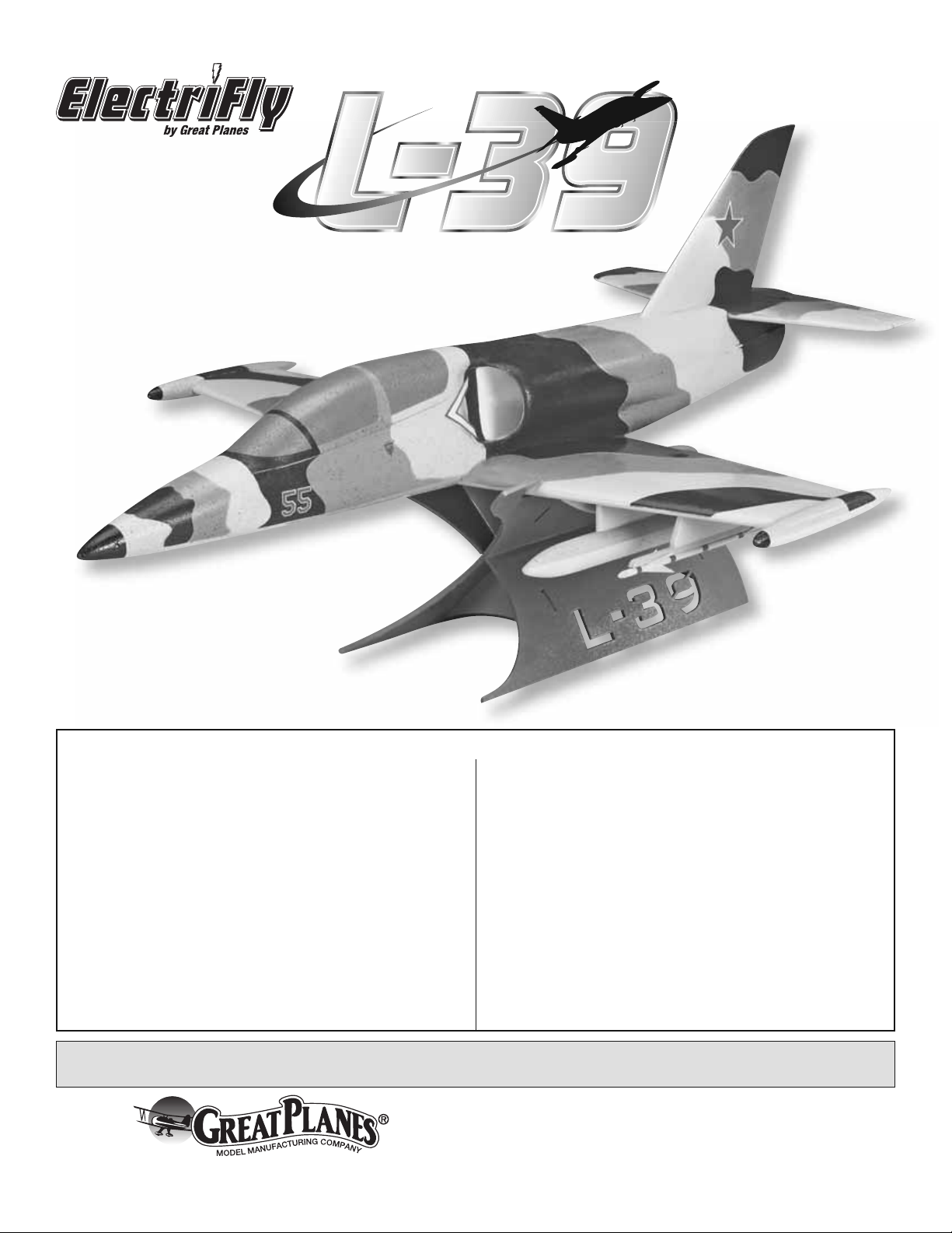
Wingspan: 25 in [635mm]
Wing Area: 141 sq in [9.1 dm2]
Weight: 17.5–18.5 oz [500–520g]
Wing Loading: 17.9–18.9 oz/sq ft [55–58 g/dm2]
Length: 31 in [780mm]
Radio: 3-Channel Minimum with 3 Micro Servos, Micro Receiver
WARRANTY
Great Planes® Model Manufacturing Co. guarantees this kit to
be free from defects in both material and workmanship at the date
of purchase. This warranty does not cover any component parts
damaged by use or modifi cation. In no case shall Great Planes’
liability exceed the original cost of the purchased kit. Further,
Great Planes reserves the right to change or modify this warranty
without notice.
In that Great Planes has no control over the fi nal assembly or
material used for fi nal assembly, no liability shall be assumed nor
accepted for any damage resulting from the use by the user of
the fi nal user-assembled product. By the act of using the userassembled product, the user accepts all resulting liability.
If the buyer is not prepared to accept the liability associated
with the use of this product, the buyer is advised to return
READ THROUGH THIS MANUAL BEFORE STARTING CONSTRUCTION. IT CONTAINS IMPORTANT
INSTRUCTIONS AND WARNINGS CONCERNING THE ASSEMBLY AND USE OF THIS MODEL.
Entire Contents © Copyright 2007
this kit immediately in new and unused condition to the place
of purchase.
To make a warranty claim send the defective part or item to Hobby
Services at the address below:
Hobby Services
3002 N. Apollo Dr., Suite 1
Champaign, IL 61822 USA
Include a letter stating your name, return shipping address, as
much contact information as possible (daytime telephone number,
fax number, e-mail address), a detailed description of the problem
and a photocopy of the purchase receipt. Upon receipt of the
package, the problem will be evaluated as quickly as possible.
Champaign, Illinois
(217) 398-8970, Ext 5
airsupport@greatplanes.com
GPMZ1869 for GPMA1869 V1.0
Page 2
TABLE OF CONTENTS
AMA
INTRODUCTION ............................................................... 2
AMA .................................................................................. 2
SAFETY PRECAUTIONS .................................................2
LITHIUM BATTERY HANDLING AND USAGE ................3
DECISIONS YOU MUST MAKE ....................................... 3
Radio Equipment .......................................................3
Speed Control ............................................................ 3
ADDITIONAL ITEMS REQUIRED .................................... 4
Adhesives and Building Supplies ............................... 4
Optional Supplies and Tools ....................................... 4
IMPORTANT BUILDING NOTES ...................................... 4
ORDERING REPLACEMENT PARTS .............................. 4
KIT CONTENTS ................................................................ 5
BEFORE YOU BEGIN ....................................................... 6
ASSEMBLE THE AIRPLANE ...........................................6
GET THE MODEL READY TO FLY ................................. 11
Check the Control Directions ................................... 11
Set the Control Throws ............................................11
Balance the Model (C.G.).........................................11
PREFLIGHT .................................................................... 12
Identify Your Model ...................................................12
Charge the Batteries ................................................ 12
Range Check ........................................................... 12
AMA SAFETY CODE ...................................................... 12
CHECK LIST ................................................................... 13
FLYING ............................................................................ 13
Takeoff ..................................................................... 13
Flight ........................................................................ 14
Landing .................................................................... 14
We urge you to join the AMA (Academy of Model Aeronautics)
and a local R/C club. The AMA is the governing body of model
aviation and membership is required to fl y at AMA clubs.
Though joining the AMA provides many benefi ts, one of the
primary reasons to join is liability protection. Coverage is not
limited to fl ying at contests or on the club fi eld. It even applies
to fl ying at public demonstrations and air shows. Failure to
comply with the Safety Code (excerpts printed in the back of
the manual) may endanger insurance coverage. Additionally,
training programs and instructors are available at AMA club
sites to help you get started the right way. There are over
2,500 AMA chartered clubs across the country. Contact the
AMA at the address or toll-free phone number below.
Academy of Model Aeronautics
5151 East Memorial Drive
Muncie, IN 47302
Tele: (800) 435-9262
Fax (765) 741-0057
Or via the Internet at:
http://www.modelaircraft.org
IMPORTANT!!! Two of the most important things you can do
to preserve the radio controlled aircraft hobby are to avoid
fl ying near full-scale aircraft and avoid fl ying near or over
groups of people.
INTRODUCTION
Welcome to the exciting world of EDF (Electric Ducted Fan)
airplanes! The L-39 is sure to please with its scale appearance
paired with the convenience of being constructed from light
weight foam. In addition, the L-39 also includes a painted
stand and removable missiles and drop tanks (for display
only) that will allow the plane to double as a display model.
Using the included brushless motor, the L-39 achieves
incredible speeds, being clocked at 78 mph coming out of a
dive! The L-39 is a great, stable fl yer too and can comfortably
fl y at slower speeds.
For the latest technical updates or manual corrections
to the L-39 ARF visit the Great Planes web site at www.
greatplanes.com. Open the “Airplanes” link, then select the
L-39 ARF. If there is new technical information or changes
to this model a “tech notice” box will appear in the upper left
corner of the page.
PROTECT YOUR MODEL, YOURSELF
& OTHERS...FOLLOW THESE
IMPORTANT SAFETY PRECAUTIONS
1. Your L-39 ARF should not be considered a toy, but rather
a sophisticated, working model that functions very much like
a full-size airplane. Because of its performance capabilities,
the L-39, if not assembled and operated correctly, could
possibly cause injury to yourself or spectators and damage
to property.
2. You must assemble the model according to the instructions.
Do not alter or modify the model, as doing so may result in
an unsafe or unfl yable model. In a few cases the instructions
may differ slightly from the photos. In those instances the
written instructions should be considered as correct.
3. You must take time to build straight, true and strong.
4. You must correctly install all R/C and other components
so that the model operates correctly on the ground and in
the air.
2
Page 3

5. You must check the operation of the model before every
fl ight to insure that all equipment is operating and that the
model has remained structurally sound. Be sure to check
pushrod connectors or servo arms often and replace them if
they show any signs of wear or fatigue.
6. If you are not an experienced pilot or have not fl own
this type of model before, we recommend that you get the
assistance of an experienced pilot in your R/C club for
your fi rst fl ights. If you’re not a member of a club, your local
hobby shop has information about clubs in your area whose
membership includes experienced pilots.
We, as the kit manufacturer, provide you with a top quality,
thoroughly tested kit and instructions, but ultimately the
quality and fl yability of your fi nished model depends
on how you build it; therefore, we cannot in any way
guarantee the performance of your completed model,
and no representations are expressed or implied as to
the performance or safety of your completed model.
DECISIONS YOU MUST MAKE
This is a partial list of items required to fi nish the L-39 EDF ARF
that may require planning or decision making before starting
to build. Order numbers are provided in parentheses.
Radio Equipment
The L-39 EDF ARF requires a 3+ channel transmitter, a micro
receiver, and three micro servos (9g or less). If you already
have a transmitter you are going to use to fl y the L-39, you
can get the receiver and servos separately:
❏ Futaba
(Low Band: FUTL0442; High Band: FUTL0443)
❏ Futaba FM Single conversion receiver crystal for R114F
(Low Band: FUTL62**; High Band: FUTL63**)
❏ Futaba S3114 Micro HT Servo (FUTM0414)
❏ Two Futaba 150mm Slim Wire Extensions (FUTM4506)
❏ Futaba 6" Dual Servo Extension J (FUTM4130)
®
R114F 4-Channel FM Micro Receiver w/o Crystal
Remember: Take your time and follow the instructions to
end up with a well-built model that is straight and true.
LITHIUM BATTERY
HANDLING & USAGE
WARNING!! Read the entire instruction sheet included with
the battery. Failure to follow all instructions could cause
permanent damage to the battery and its surroundings, and
cause bodily harm!
• ONLY use a LiPo approved charger. NEVER use a NiCd/
NiMH peak charger!
• NEVER charge in excess of 4.20V per cell.
• ONLY charge through the “charge” lead. NEVER charge
through the “discharge” lead.
• NEVER charge at currents greater than 1C.
• ALWAYS set charger’s output volts to match battery volts.
• ALWAYS charge in a fi reproof location.
• NEVER trickle charge.
• NEVER allow battery temperature to exceed 150° F (65° C).
• NEVER disassemble or modify pack wiring in any way or
puncture cells.
• NEVER discharge below 2.5V per cell.
• NEVER place on combustible materials or leave unattended
during charge or discharge.
• ALWAYS KEEP OUT OF REACH OF CHILDREN.
A lithium-polymer battery pack and suitable charger are
also required. Although there are different battery packs
and chargers available that will work with the L-39 ARF, the
economical choices recommended by Great Planes are:
❏ Great Planes LiPo 11.1V 910mAh 20C Discharge
w/Balance (GPMP0605)
❏ Great Planes LiPo 11.1V 1250mAh 20C Discharge
w/Balance (GPMP0609)
❏ Great Planes ElectriFly DC peak charger (GPMM3010)
❏ Great Planes Equinox
Note: Battery choice will affect the balance of the plane. The
1250mAh pack will result in a forward C.G. position, and the
910mAh pack will provide a more aft C.G. position.
™
Cell Balancer (GPMM3160)
Speed Control
A 25A brushless electronic speed control with BEC (Battery
Eliminator Circuitry) is required. The BEC allows both the
motor and the radio system to be powered by the same
battery (thus eliminating the on-board receiver battery). The
Great Planes Silver Series 25A Brushless ESC (GPMM1820)
is recommended.
3
Page 4
ADDITIONAL ITEMS REQUIRED
ORDERING REPLACEMENT PARTS
Adhesives and Building Supplies
Foam safe CA glue and 30-minute epoxy are used in the
assembly of the L-39 ARF. Order numbers are provided below.
❏ Great Planes Pro
(GPMR6043)
™
Epoxy 30-Minute Formula 4 oz.
❏ Great Planes Pro Foam Safe CA- Thick Glue 1 oz.
(GPMR6072)
❏ Denatured alcohol (for epoxy clean up)
This manual also refers to using a 1/16" [1.6 mm] drill bit:
❏ Hobbico
®
Pin Vise 1/16 Collet w/6 Bits (HCAR0696)
Optional Supplies and Tools
Here is a list of items that will help you build the L-39 ARF.
❏ CA debonder (GPMR6039)
❏ Epoxy brushes (6, GPMR8060)
❏ Mixing sticks (50, GPMR8055)
❏ Mixing cups (GPMR8056)
❏ CG Machine
™
(GPMR2400)
❏ Hobbico Flexible 18" Ruler Stainless Steel (HCAR0460)
IMPORTANT BUILDING NOTES
• When you see the term test fi t in the instructions, it means
that you should fi rst position the part on the assembly
without using any glue, then slightly modify or custom fi t
the part as necessary for the best fi t.
• Whenever the term glue is written you should rely upon
your experience to decide what type of glue to use. When
a specifi c type of adhesive works best for that step, the
instructions will make a recommendation.
• Whenever just epoxy is specifi ed you may use either
30-minute (or 45-minute) epoxy or 6-minute epoxy. When
30-minute epoxy is specifi ed it is highly recommended that
you use only 30-minute (or 45-minute) epoxy, because you
will need the working time and/or the additional strength.
• Photos and sketches are placed before the step they
refer to. Frequently you can study photos in following steps
to get another view of the same parts.
Replacement parts for the L-39 ARF are available using the
order numbers in the Replacement Parts List that follows. The
fastest, most economical service can be provided by your
hobby dealer or mail-order company.
To locate a hobby dealer, visit the Great Planes web site
at www.greatplanes.com. Choose “Where to Buy” at the
bottom of the menu on the left side of the page. Follow the
instructions provided on the page to locate a U.S., Canadian
or International dealer.
Parts may also be ordered directly from Hobby Services by
calling (217) 398-0007, or via facsimile at (217) 398-7721,
but full retail prices and shipping and handling charges will
apply. Illinois and Nevada residents will also be charged
sales tax. If ordering via fax, include a Visa
number and expiration date for payment.
Mail parts orders and payments by personal check to:
Hobby Services
3002 N. Apollo Drive, Suite 1
Champaign, IL 61822
Be certain to specify the order number exactly as listed in
the Replacement Parts List. Payment by credit card or
personal check only; no C.O.D.
If additional assistance is required for any reason, contact
Product Support by telephone at (217) 398-8970, or by
e-mail at productsupport@greatplanes.com.
Replacement Parts List
Order Number Description How to Purchase
Missing pieces ............... Contact Product Support
Instruction manual ..........Contact Product Support
Full-size plans ...................................Not available
Contact your hobby supplier for the following parts:
GPMA2772 ........... Wing Set with Tip Tanks
GPMA2773 ........... Fuse Kit with Hatch
GPMA2774 ........... Tail Set
GPMA2775 ........... Canopy Hatch
GPMA2776 ........... Armament Set
GPMA2777 ........... Display Stand
GPMA2778 ........... Tip Tanks (2)
GPMA2779 ........... Decal Sheet
GPMA3124 ........... Motor Lead Extension
GPMG3900 ........... HyperFlow Ducted Fan Unit
GPMG3940 ........... Ducted Fan Rotor Blade
GPMG3941 ........... Ducted Fan Miscellaneous Parts
GPMG3942 ........... Ducted Fan Outer Duct
GPMG3943 ........... Ducted Fan Adapter
®
or MasterCard®
4
Page 5
KIT INSPECTION
Before starting to build inspect the parts to make sure they are of acceptable quality. If any parts are missing or are not
of acceptable quality, or if you need assistance with assembly, contact Product Support. When reporting defective or
missing parts, use the part names exactly as they are written in the Kit Contents list.
Great Planes Product Support
3002 N. Apollo Drive, Suite 1
Champaign, IL 61822
Telephone: (217) 398-8970, ext. 5
Fax: (217) 398-7721
E-mail: airsupport@greatplanes.com
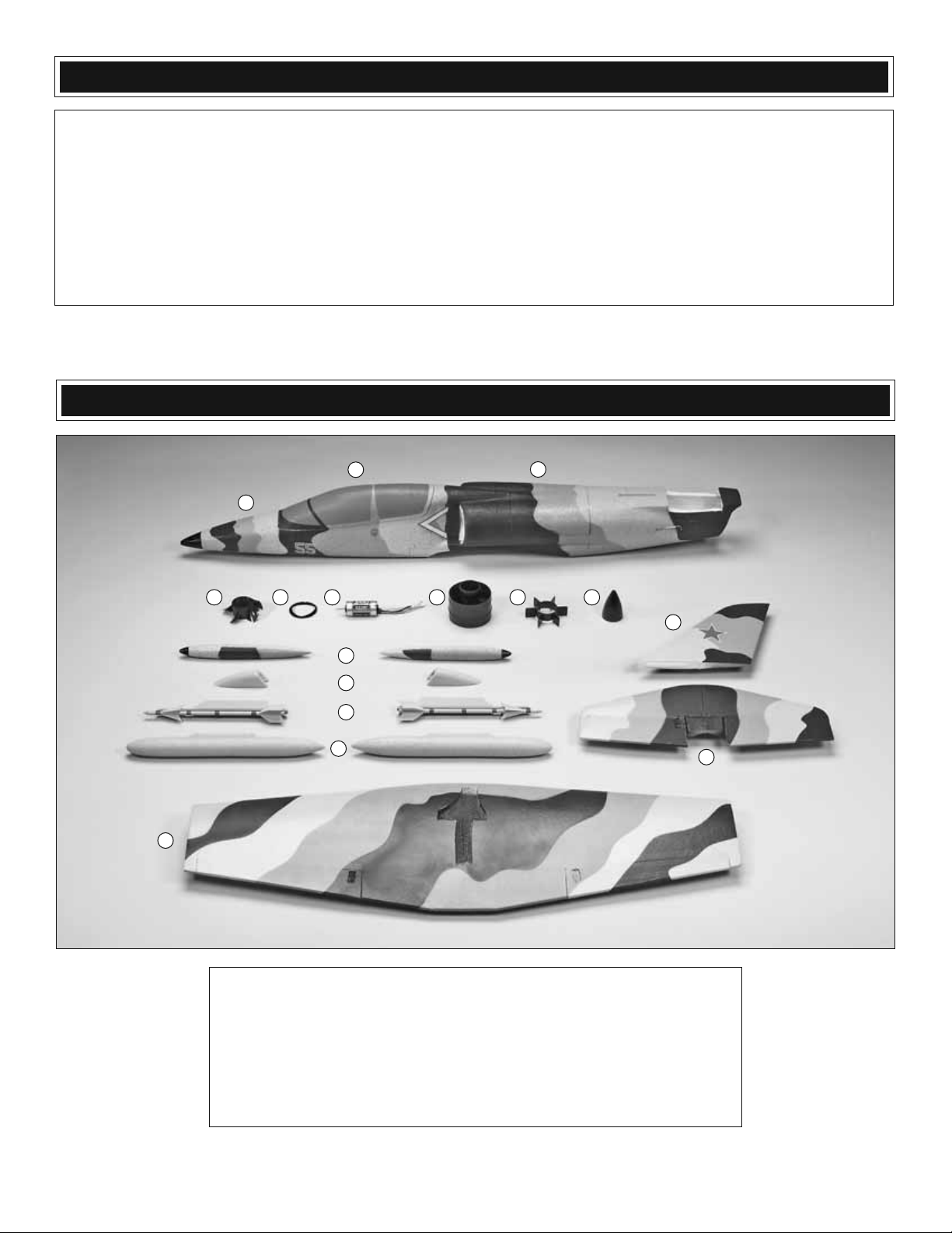
KIT CONTENTS
6
1
11 12 13 14 15 16
10
9
8
7
3
2
5
4
1. Fuselage
2. Ducted Fan Access Hatch
3. Wing w/Ailerons
4. Horizontal Stabilizer w/Elevators
5. Vertical Fin
6. Canopy Hatch
7. Drop Tanks (2)
8. Missiles (2)
9. Aileron Pushrod Covers (2)
10. Wing Tip Tanks (2)
11. Rotor
12. 20mm Motor Adapter
13. Brushless Motor
14. Ducted Fan Housing
15. Stator Extension
16. Aft Cone
5
Page 6

BEFORE YOU BEGIN
Before building the model, please follow the assembly and
break-in instructions that can be found in the manual that
accompanies the included ducted fan unit. Two 2.5mm x 5mm
machine screws and two 2.5mm fl at washers are included to
mount the Ammo™ 20-40-3500kV brushless motor inside the
fan housing.
❏ 2. Attach a 6" [150mm] servo extension to each aileron
servo. Use tape or heat shrink tubing (not included) to secure
the connectors.
ASSEMBLE THE AIRPLANE
❏ 1. Begin by centering the aileron servos with your radio
system. Cut three arms from two four-armed servo arms.
Enlarge the outer holes in the servo arms with a 1/16"
[1.6mm] drill bit. Attach the servo arms perpendicular to the
aileron servo cases using the servo arm screws (be sure to
make a left and right aileron servo).
❏ 3. Glue the servos into the aileron servo bays using CA
glue or epoxy. Route the servo leads down the servo lead
channel and through the slots near the center of the wing.
666
Page 7

❏ 4. Connect a pushrod wire with Z-bend to each of the
aileron servo arms.
❏ 5. Use the included thumb screw pushrod connectors to
connect the aileron pushrods to the outer holes in the control
horns as shown. Center the ailerons in the neutral position
and tighten the thumb screws against the pushrods.
❏ 7. Attach the wing tip tanks to the wing as shown. The
magnets will hold them in place during fl ight.
❏ 8. Connect the included motor lead extensions to the
three wires on the motor. Secure the extensions using tape
(not included).
❏ 6. Glue the aileron pushrod covers over the servo arms.
Be sure that the covers are positioned so that they will not
interfere with the pushrods when the ailerons are defl ected
up and down.
❏ 9. Test fi t the ducted fan unit into the fuselage channel
by feeding the motor lead extensions through the hole in the
bottom of the channel and aligning the unit with the molded
grooves in the channel. Confi rm that the rotor cone does not
contact any part of the fuselage. If necessary, use a hobby
knife to carefully trim the contacting area away from the fuse.
When satisfi ed, use 30-minute epoxy to glue the ducted fan
unit into the duct channel. Clean up any excess epoxy with
a dry paper towel.
7
Page 8

❏ 10. Position the motor lead extensions into the slot in the
fuselage, down the channel in the wing saddle, and through
the hole to the radio compartment.
❏ 12. Install the ducted fan access hatch onto the fuselage.
The pre-installed magnets will secure it during fl ight.
❏ 11. Coat the wing saddle on the fuselage with 30-minute
epoxy. Insert the aileron servo wires through the hole in the
fuse and into the radio compartment. Place the wing onto the
saddle by fi tting the alignment keys on the top of the wing
into the mating cutouts in the wing saddle. Tape the wing to
the fuse while the epoxy cures or place a weight on the top
of the fuse to press it against the wing. If using tape, avoid
damaging the paint by fi rst lining the outside of the model
with sheets of paper or something similar. Wrap the tape
tightly around the paper instead of directly onto the model.
8
Page 9

❏ 13. The vertical fi n and horizontal stabilizer are keyed
to fi t together and therefore must be glued in place at the
same time. Coat with epoxy the key on the bottom of the fi n,
the slot in the horizontal stabilizer, and the stab saddle on
the fuselage. Do not put epoxy on the foam piece glued to
the front of the fi n that fi ts into the ducted fan access hatch.
Position the parts onto the fuselage, making sure that the
vertical fi n is being glued square to the horizontal stabilizer.
The parts can be taped in place while the epoxy cures.
❏ 16. Make a small, upward bend in the elevator pushrod
as shown. Fit the pushrod through the screw-lock connector
and attach the servo arm to the servo using the servo arm
screw. Insert the 90° bend (at the aft end) into the outer hole
of the elevator control horn. Secure it using the 90° pushrod
connector. Use your radio system to center the elevator servo.
Position the elevators in the neutral position and tighten the
screw-lock connector against the pushrod.
❏ 14. Glue the elevator servo into the elevator servo bay inside
the radio compartment with the splines facing forward. There
is a slot at the bottom of the servo bay for the servo lead.
❏ 15. Cut three arms from a four-armed servo arm. Enlarge
the outer hole of the servo arm with a 1/16" [1.6mm] drill
bit. Attach the screw-lock connector to the outer hole of the
servo arm and secure it with the plastic retainer.
❏ 17. Connect your ESC to the motor lead extensions and
connect the servos and ESC to the receiver. This is a good
time to confi rm the correct rotation of your ducted fan unit. If the
unit rotates the wrong direction when powered up, disconnect
two of the three motor leads and swap their positions.
9
Page 10

❏ 18. Feed the receiver antenna through the antenna tube
and out the back of the fuselage. Use the included doublesided tape to secure the ESC and receiver to the side of the
radio compartment. Be sure they are positioned at the back
of the compartment and that the wires are tucked neatly out
of the way.
❏ 19. Apply the hook side of the included hook and loop
material to the bottom of the radio compartment. Brushing
on a thin coat of epoxy and letting it cure before attaching the
hook material will help it adhere to the foam. Apply the loop
side to your battery pack.
❏ 20. Assemble and glue the display stand together as
shown using foam-safe glue. The long slots in the two large
pieces interlock and the four cross braces are glued into the
small slots.
❏ 24. Finish the model by test fi tting the removable drop
tanks and missiles to the underside of the wing. These parts
are attached magnetically and are for display purposes only.
Be sure to remove them prior to fl ight!
10
Page 11

GET THE MODEL READY TO FLY
Check the Control Directions
❏ 1. Turn on the transmitter and receiver and center the trims.
❏ 2. With the transmitter and receiver still on, check all the
control surfaces to see if they are centered. If necessar y, adjust
the pushrod connectors on the control surface pushrods.
3-CHANNEL RADIO SETUP
(STANDARD MODE 2)
ELEVATORS MOVE UP
RIGHT AILERON MOVES UP
LEFT AILERON MOVES DOWN
These are the recommended control surface throws:
High Rate Low Rate
ELEVATOR: 5/16" [8mm] up 1/8" [3.2mm] up
5/16" [8mm] down 1/8" [3.2mm] down
AILERONS: 3/16" [4.8mm] up 3/32" [2.4mm] up
3/16" [4.8mm] down 3/32" [2.4mm] down
NOTE: The throws are measured at the widest part of
the control surfaces.
IMPORTANT: The L-39 ARF has been extensively fl own
and tested to arrive at the throws at which it fl ies best. Flying
your model at these throws will provide you with the greatest
chance for successful fi rst fl ights. If, after you have become
accustomed to the way the L-39 fl ies, you would like to
change the throws to suit your taste, that is fi ne. However,
too much control throw could make the model diffi cult to
control, so remember, “more is not always better.”
FULL THROTTLE
❏ 3. Make certain that the control surfaces and the throttle
respond in the correct direction as shown in the diagram.
If any of the controls respond in the wrong direction, use
the servo reversing in the transmitter to reverse the servos
connected to those controls. Be certain the control surfaces
have remained centered. Adjust if necessary.
Set the Control Throws
Use a Great Planes AccuThrow™ (or a ruler) to accurately
measure and set the control throw of each control surface
as indicated in the chart that follows. If your radio does not
have dual rates, we recommend setting the throws at the
low rate setting.
Balance the Model (C.G.)
More than any other factor, the C.G. (balance point)
can have the greatest effect on how a model fl ies, and
may determine whether or not your fi rst fl ight will be
successful. If you value this model and wish to enjoy it for
many fl ights, DO NOT OVERLOOK THIS IMPORTANT
PROCEDURE. A model that is not properly balanced will
be unstable and possibly unfl yable.
At this stage the model should be in ready-to-fl y condition
with all of the systems in place including the receiver, ESC,
and battery pack.
❏ 1. The C.G. is located 1-15/16" [49mm] back from
the leading edge of the wing at the fuselage (the seam
where the wing panels have been joined to the fuselage).
If you mark the C.G. position onto the top of the wing, be
very careful if using tape as it could damage the paint when
removed. Also, do not attempt to remove felt-tip pen marks
with alcohol. We suggest making small marks on the wing
beneath the ducted fan inlets.
This is where your model should balance for the fi rst
fl ights. Later, you may wish to experiment by shifting the
C.G. up to 3/16" [4.8mm] forward or 1/8" [3.2mm] back to
change the fl ying characteristics. Moving the C.G. forward
may improve the smoothness and stability, but the model
may be more diffi cult to slow for landing. Moving the C.G.
aft makes the model more maneuverable, but could also
cause it to become too diffi cult to control. In any case,
start at the recommended balance point and do not at
any time balance the model outside the specifi ed range.
11
Page 12

❏ 2. With all parts of the model installed (ready to fl y), place
the model upside-down on a Great Planes CG Machine, or
lift it upside down at the balance point you marked.
Range Check
Ground check the operational range of your radio before the
fi rst fl ight of the day. With the transmitter antenna collapsed
and the receiver and transmitter on, you should be able to
walk at least 100 feet away from the model and still have
control. Have an assistant stand by your model and, while
you work the controls, tell you what the control surfaces are
doing. Repeat this test with the motor running at various
speeds with an assistant holding the model, using hand
signals to show you what is happening. If the control surfaces
do not respond correctly, do not fl y! Find and correct the
problem fi rst. Look for loose servo connections or broken
wires, corroded wires on old servo connectors, poor solder
joints in your battery pack or a defective cell, or a damaged
receiver crystal from a previous crash.
❏ 3. If the tail drops, the model is “tail heavy” and the
battery pack and/or receiver must be shifted to balance. If
the nose drops, the model is “nose heavy” and the battery
pack and/or receiver must be shifted to balance. This model
is very weight sensitive. We do not recommend adding any
additional weight to achieve the suggested balance point
unless absolutely necessary. Instead, shift the battery pack
and receiver forward or aft to alter the C.G.
PREFLIGHT
Identify Your Model
No matter if you fl y at an AMA sanctioned R/C club site or
if you fl y somewhere on your own, you should always have
your name, address, telephone number and AMA number
on or inside your model. It is required at all AMA R/C club
fl ying sites and AMA sanctioned fl ying events. Fill out the
identifi cation tag on the back cover of this manual and place it
on or inside your model.
Charge the Batteries
AMA SAFETY CODE (EXCERPTS)
Read and abide by the following excerpts from the Academy
of Model Aeronautics Safety Code. For the complete Safety
Code refer to Model Aviation magazine, the AMA web site or
the Code that came with your AMA license.
General
1) I will not fl y my model aircraft in sanctioned events, air
shows, or model fl ying demonstrations until it has been
proven to be airworthy by having been previously,
successfully fl ight tested.
2) I will not fl y my model aircraft higher than approximately
400 feet within 3 miles of an airport without notifying the
airport operator. I will give right-of-way and avoid fl ying
in the proximity of full-scale aircraft. Where necessary,
an observer shall be utilized to supervise fl ying to avoid
having models fl y in the proximity of full-scale aircraft.
3) Where established, I will abide by the safety rules for the
fl ying site I use, and I will not willfully and deliberately fl y my
models in a careless, reckless and/or dangerous manner.
Follow the battery charging instructions that came with your
radio control system to charge the batteries. You should
always charge your transmitter and motor batteries the night
before you go fl ying, and at other times as recommended by
the manufacturer.
CAUTION: Unless the instructions that came with your
radio system state differently, the initial charge on new
transmitter batteries should be done for 15 hours using
the slow-charger that came with the radio system.
This will “condition” the batteries so that the next charge
may be done using the fast-charger of your choice. If the
initial charge is done with a fast-charger the batteries
may not reach their full capacity and you may be fl ying
with batteries that are only partially charged.
5) I will not fl y my model unless it is identifi ed with my name
and address or AMA number, on or in the model. Note:
This does not apply to models while being fl own indoors.
7) I will not operate models with pyrotechnics (any device
that explodes, burns, or propels a projectile of any kind).
Radio Control
1) I will have completed a successful radio equipment ground
check before the fi rst fl ight of a new or repaired model.
2) I will not fl y my model aircraft in the presence of spectators
until I become a qualifi ed fl ier, unless assisted by an
experienced helper.
12
Page 13

3) At all fl ying sites a straight or curved line(s) must be
established in front of which all fl ying takes place with the
other side for spectators. Only personnel involved with
fl ying the aircraft are allowed at or in the front of the fl ight
line. Intentional fl ying behind the fl ight line is prohibited.
4) I will operate my model using only radio control frequencies
currently allowed by the Federal Communications Commission.
5) I will not knowingly operate my model within three miles
of any pre-existing fl ying site except in accordance with
the frequency sharing agreement listed [in the complete
AMA Safety Code].
9) Under no circumstances may a pilot or other person touch
a powered model in fl ight; nor should any part of the
model other than the landing gear, intentionally touch
the ground, except while landing.
CHECK LIST
FLYING
IMPORTANT: If you are an inexperienced modeler we strongly
urge you to seek the assistance of a competent, experienced
R/C pilot to check your model for airworthiness AND to teach
you how to fl y. No matter how stable or “forgiving” the L-39 is,
attempting to learn to fl y on your own is dangerous and may
result in destruction of your model or even injury to yourself
and others. Therefore, fi nd an instructor and fl y only under
his or her guidance and supervision until you have acquired
the skills necessary for safe and fully controlled operation of
your model.
Takeoff
Less-experienced fl yers should fl y the L-39 only in calm
(less than fi ve miles per hour) conditions. Frequently, winds
are calm in the early morning and early evening. Often these
are the most enjoyable times to fl y anyway!
During the last few moments of preparation your mind may
be elsewhere anticipating the excitement of the fi rst fl ight.
Because of this, you may be more likely to overlook certain
checks and procedures that should be performed before
the model is fl own. To help avoid this, a check list is provided
to make sure these important areas are not overlooked.
Many are covered in the instruction manual, so where
appropriate, refer to the manual for complete instructions.
Be sure to check the items off as they are completed.
❏ 1. Check the C.G. according to the measurements provided
in the manual.
❏ 2. Be certain the battery and receiver are securely mounted
in the fuse.
❏ 3. Confi rm that all controls operate in the correct direction
and the throws are set up according to the manual.
❏ 4. Check the operation of the ducted fan unit prior to
each fl ight.
❏ 5. Make sure that all servo arms are secured to the servos
wtih the screws included with your radio.
❏ 6. Place your name, address, AMA number and telephone
number on or inside your model.
❏ 7. If you wish to photograph your model, do so before your
fi rst fl ight.
❏ 8. Range check your radio when you get to the fl ying fi eld.
Until you have the L-39 properly trimmed for level fl ight, we
recommend having an assistant hand-launch the model
instead of launching it yourself.
Turn on the transmitter and plug the battery into the speed
control. Turn on the receiver by following the instructions
that came with your speed control. Secure the canopy hatch
in place.
IMPORTANT: Confi rm that the transmitter operates the
controls properly by moving the sticks and watching the
surfaces respond.
When ready to launch, the assistant should hold the L-39
behind the canopy hatch, with the model in front of him and
pointed into the wind. With the pilot (that would be you!)
standing behind the plane, fully advance the throttle to start
the motor. When the motor is at full power, the hand launcher
should fi rmly give the model an underhand toss into the air
with a slightly nose-up attitude. Be certain the model is being
launched into the wind and be immediately ready to make
corrections to keep the airplane fl ying straight, level and into
the wind.
When the model has gained adequate fl ying speed under
its own power, gently pull the elevator stick back until the
airplane starts a gradual climb. Many beginners tend to pull
too hard causing the model to stall, so be gentle on the
elevator and don’t panic. If you do pull too hard and you
notice the model losing speed, release the elevator stick and
allow the model to regain airspeed.
Continue a gradual climb and establish a gentle turn (away
from yourself and others) until the airplane reaches an
altitude of 20 to 30 meters [75 to 100 feet].
13
Page 14

Flight
Landing
The main purpose of the fi rst few fl ights is to learn how the
model behaves and to adjust the trims for level fl ight. After the
model has climbed to a safe altitude, reduce the throttle slightly
to slow the model, yet maintain altitude. The L-39 should fl y
well and maintain adequate airspeed at about 1/2 throttle.
Adjust the elevator trim so the model fl ies level at the throttle
setting you are using. Adjust the aileron trim to level the wings.
It may take a few minutes to get the trims adjusted, but this
should be your fi rst priority once at a comfortable altitude.
Continue to fl y around, executing turns and making mental
notes (or having your assistant take notes for you) of what
additional adjustments or C.G. changes may be required to
fi ne tune the model so it fl ies the way you like.
OTHER ITEMS AVAILABLE FROM GREAT PLANES
Begin the landing approach by fl ying downwind at an altitude
of approximately 6 meters [20 feet]. When the airplane is
approximately 15 to 30 meters [50 to 100 feet] past you,
gradually reduce power and make the “fi nal” 180° turn into
the wind aligning the airplane with the runway or landing
area. Do not dive the airplane, as it will pick up too much
speed. Instead, allow the airplane to establish a gradual
descent. Concentrate on keeping it heading into the wind
toward the runway. When the plane reaches an altitude of
about 3 feet [1 meter], gently apply a little “up elevator” to
level the plane, but be careful as too much up elevator will
cause it to stall. While holding a slight amount of up elevator
the airplane will slow and descend as it loses fl ying speed,
thus touching-down on the runway.
Until you are able to accurately judge how far the L-39 can
glide, it may be helpful to reserve some battery power to run
the motor so the plane can be fl own back to the runway.
Best of luck and happy fl ying!
ElectriFly™ Triton™ Jr.
DC Computerized Peak Charger, Discharger & Cycler
Perfect for smaller-sized, electric aircraft!
It’s the compact, more affordable version of the Triton2! While it may not have all the features of its big brother, the Triton Jr. can still handle
many of your charging needs. It works with all the same types of batteries (NiCd, NiMH, LiPo and lead-acid), and has the same blue
backlit LCD screen. The Triton Jr. can charge at up to 5 amps, discharge up to 1 amp, or cycle up to 5 times — and programming is very
straightforward on the rugged, 4-direction membrane touchpad. At just over 4-1/2" long, 3-1/2" wide and 13 oz, the Triton Jr. fi ts easily into
any fi eld box, and the unit is enclosed in a durable aluminum case. GPMM3152
Battery Types, # of Cells: 1-14 NiCd/NiMH
1-4 LiPo/Li-Ion (3.6 or 3.7V cells)
2, 4, 6, 8, 10, 12V Pb
Fast Charge Current: 0.1-5.0A NiCd/NiMH (0.1A step, 63W max.)
1C rating LiPo/Li-Ion (63W max.)
Peak Delay at Start: 3 minutes fi xed
Discharge Current: 0.1-1.0A (o.01 step, 5W max.)
Cycle Count: 1 only, C>D or D>C
Battery Memory: One
Display Type: 2 x 16 LCD, blue backlight
Case Size: 4.7" x 3.6" x 1.2"
Weight: 13.1 oz.
14
Page 15

OTHER ITEMS AVAILABLE FROM GREAT PLANES
ElectriFly Equinox™ LiPo 1-5 Cell Balancer
By regulating the voltage levels from 2 to 5 LiPo cells to within a very tight
tolerance of each other, the Equinox ensures the fullest possible safe voltage
during charging — which means more power and longer lasting packs! It can
handle a maximum current of 3 amps during charge or discharge (up to 6
amps with custom connectors), and includes adapters for 2S and 3S (7.4V &
11.1V) batteries and gold-plated banana plugs. Plus, it automatically checks
for poor quality cells, and provides a safe platform for charging*. Choose from
two modes for using Equinox: connected directly to the cell in “Quick Balance”
mode, or in conjunction with a LiPo-compatible charger/discharge in “Interface”
mode. GPMM3160
*Equinox cannot be used with LiPo batteries which have built-in charge protection circuits.
ElectriFly™ Silver Series SS25 Brushless Electronic Speed Control
Silver Series ESCs are compatible with NiCd, NiMH, and LiPo batteries, with automatic
low-voltage cut-off for all. The SS25 features fully proportional forward and smooth
throttle response with on/off brake. Connectors are installed and a 180-day warranty
is included. GPMM1820
Input Voltage: 7.2-14.8V
Max. Continuous Current: 25A
BEC: 5V/2.0A
Dimensions: 1.58"x0.31"x1.02" (40x8x26mm)
Weight: 0.92 oz (26g)
Battery Connector: Deans Ultra
ElectriFly™ PolyCharge4
™
For convenience with multiple LiPo packs, there’s the DC PolyCharge4.
Each of its four independent outputs can charge a one-to-four cell LithiumPolymer pack. It’s ideal if you don't have the time for one-at-a-time charging
- and don’t want the expense and hassle of multiple chargers. Each output
can handle packs from 300 to 3000mAh. Set the capacity, and PolyCharge4
will automatically set the charge rate to get you started - and use light and
sound cues to tell you when your pack is done. GPMM3015
Futaba® S3114 High Torque Micro Servo
Ideal for electric planes and small electric helis, the affordable,
analog S3114 delivers plenty of power and performance in a
compact package.
Torque @ 6.0V: 23.6 oz/in; Torque @ 4.8V: 21 oz/in
Speed @ 6.0V: 0.09 sec/60°; Speed @ 4.8V: .10 sec/60°
Dimensions: .86"x.43"x.78" (21.8x11x19.8mm)
Weight: .275 oz (7.8 g)
15
Page 16

BUILDING NOTES
Kit Purchased Date: ___________________________
Where Purchased: ____________________________
Date Construction Started: _____________________
FLIGHT LOG
Date Construction Finished: _______________________
Finished Weight: _______________________________
Date of First Flight: ______________________________
 Loading...