

Page 1
WARRANTY
Great Planes®Model Manufacturing Co. guarantees this kit to be free from defects in both material and workmanship at the date of purchase.
This warranty does not cover any component parts damaged by use or modification. In no case shall Great Planes’ liability exceed the
original cost of the purchased kit. Fur ther, Great Planes reserves the right to change or modify this warranty without notice.
In that Great Planes has no control over the final assembly or material used for final assembly, no liability shall be assumed nor accepted for
any damage resulting from the use by the user of the final user-assembled product.By the act of using the user-assembled product, the user
accepts all resulting liability.
If the buyer is not prepared to accept the liability associated with the use of this product, the buyer is advised to return this kit
immediately in new and unused condition to the place of purchase.
To make a warranty claim send the defective part or item to Hobby Services at the address below:
Hobby Services
3002 N. Apollo Dr., Suite 1
Champaign, IL 61822
USA
Include a letter stating your name, return shipping address, as much contact information as possible (daytime telephone number, fax number,
e-mail address), a detailed description of the problem and a photocopy of the purchase receipt. Upon receipt of the package the problem will
be evaluated as quickly as possible.
READ THROUGH THIS MANUAL BEFORE STARTING
CONSTRUCTION.IT CONT AINS IMPOR T ANT INSTR UCTIONS
AND WARNINGS CONCERNING THE ASSEMBLY AND
USE OF THIS MODEL.
GPMZ1866 for GPMA1866/1868 V1.0Entire Contents © Copyright 2006
Champaign, Illinois
(217) 398-8970, Ext 5
airsupport@greatplanes.com
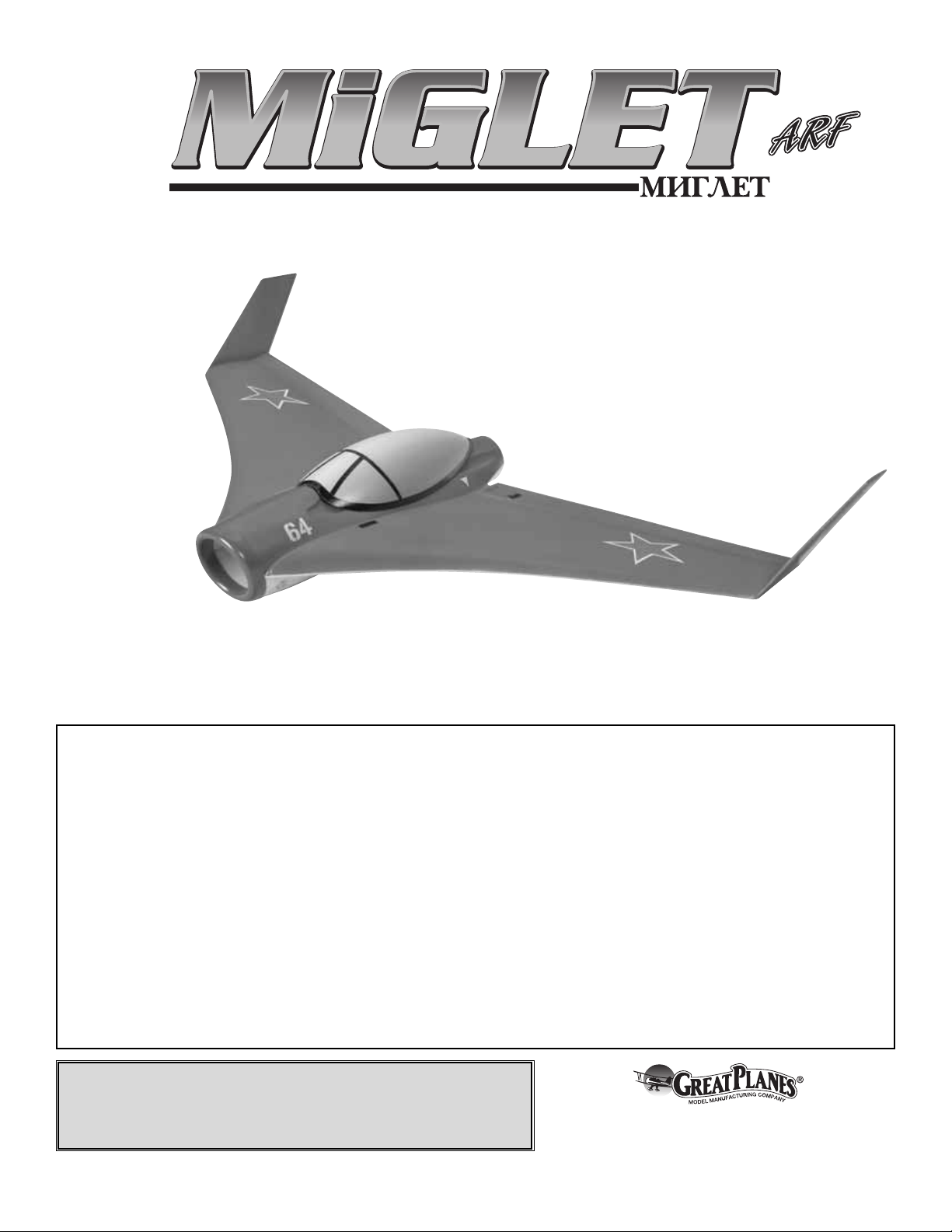
INSTRUCTION MANUAL
Wingspan: 28 in [710 mm]
Wing Area: 209 sq in [13.4 dm2]
Weight: 12 – 13 oz [340 – 370 g]
Wing Loading: 8.3 – 8.9 oz/sq ft [25 – 27 g/dm2]
Length: 15 in [380 mm]
Radio: 3-channel minimum with elevon mixing, 2 micro servos,
micro receiver
Page 2
2
INTRODUCTION ...............................................................2
AMA...................................................................................2
SAFETY PRECAUTIONS..................................................2
LITHIUM BATTERY HANDLING & USAGE .....................3
DECISIONS YOU MUST MAKE........................................3
Radio Equipment & Electronics...................................3
Motor ...........................................................................4
Electronic Speed Control (ESC)..................................4
ADDITIONAL ITEMS REQUIRED.....................................4
Adhesives & Building Supplies....................................4
Optional Supplies & Tools ...........................................4
IMPORTANT BUILDING NOTES ......................................4
ORDERING REPLACEMENT PARTS ..............................4
COMMON ABBREVIATIONS............................................5
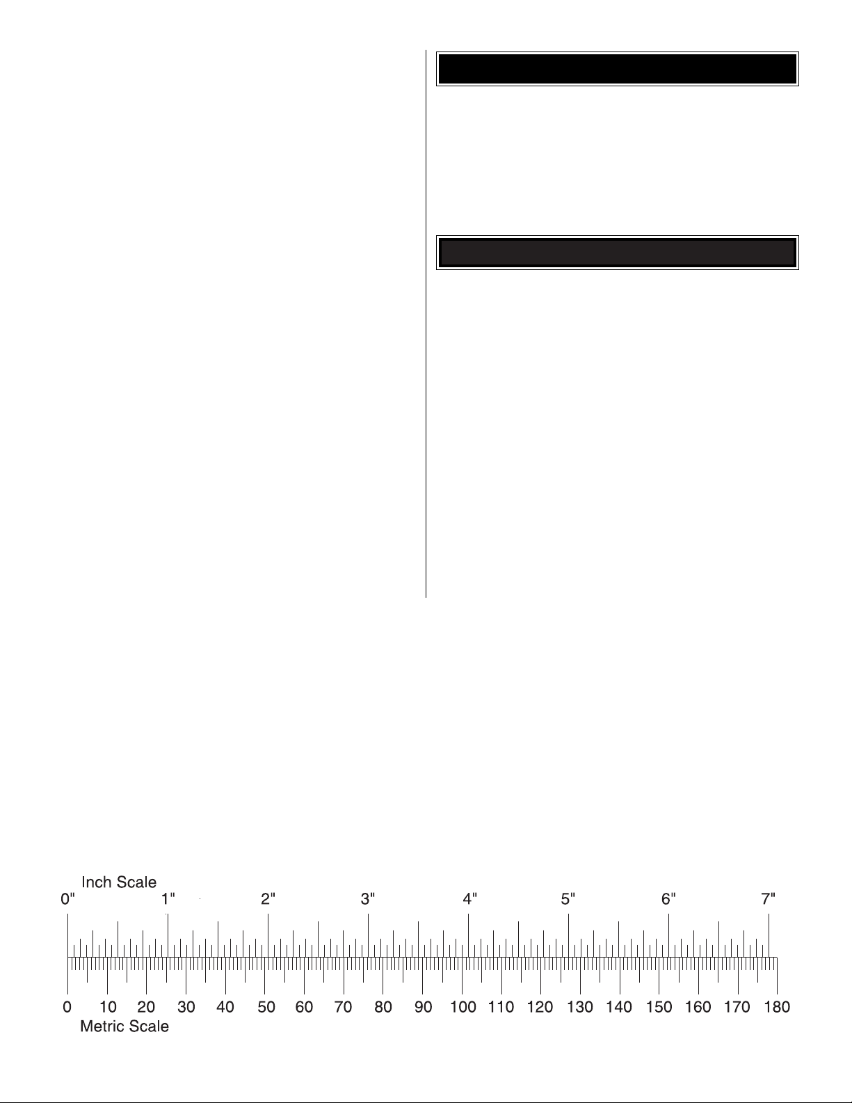
METRIC CONVERSIONS .................................................5
METRIC/INCH RULER......................................................5
KIT INSPECTION..............................................................6
KIT CONTENTS ................................................................6
BEFORE Y OU BEGIN .......................................................7
ASSEMBLE THE AIRPLANE............................................7
Install the Wing Tips & Ducted Fan Unit......................7
Install the Servos.........................................................8
Install the Electronics ................................................10
GET THE MODEL READY TO FLY .................................12
Check the Control Directions ....................................12
Set the Control Throws..............................................12
Balance the Model (C.G.)..........................................13
PREFLIGHT.....................................................................13
Identify Your Model ....................................................13
Charge the Batteries .................................................13
Range Check.............................................................13
AMA SAFETY CODE (excerpts)....................................14
CHECK LIST ...................................................................14
FLYING ............................................................................14
Takeoff.......................................................................14
Flight..........................................................................15
Landing......................................................................15
Welcome to the exciting world of EDF (Electric Ducted Fan)
airplanes. What you have in your hands could be called a
completely new generation of EDF airplanes and fans.
Historically, ducted fan airplanes have been complex and
costly. Only pilots with extensive experience knew how to
handle them. When designing this EDF, Great Planes set out
to make EDF planes that anyone can fly, while still delivering
the performance associated with them.What you have in your
hands is a fan/airplane design that only requires a 370 BB
brushed motor and a single 910mAh LiPo battery to push the
plane to straight-and-level speeds o ver 55 mph, and more than
65 mph after a short dive.This MiGLET ARF can also climb at
angles over 50 degrees and land at only 18 mph.The airplane
handles like a high-performance machine at high speeds and
control throws, but it is as easy to fly as any low wing airplane
at low speeds and control throws.Another great feature is the
extreme ease of launch as the fan thrust increases airspeed
immediately as the plane leaves the pilot’s hand.The MiGLET
ARF will change the way you think about EDF airplanes, fan
units and motors.This is the first design of many to come for
the Great Planes 370 EDF unit. Build the airplane per the
instructions and enjoy. Note: This model is also available with
the flying wing only (370 EDF unit not included, GPMA1868).
For the latest technical updates or manual corrections to the
MiGLET ARF visit the Great Planes web site at
www.greatplanes.com. Open the “Airplanes” link, then
select the MiGLET ARF. If there is new technical information
or changes to this model a “tech notice” box will appear in
the upper left corner of the page.
We urge you to join the AMA (Academy of Model
Aeronautics) and a local R/C club.The AMA is the governing
body of model aviation and membership is required to fly at
AMA clubs.Though joining the AMA provides many benefits,
one of the primary reasons to join is liability protection.
Coverage is not limited to flying at contests or on the club
field. It even applies to flying at public demonstrations and
air shows. Failure to comply with the Safety Code (excerpts
printed in the back of the manual) may endanger insurance
coverage.Additionally, training programs and instructors are
available at AMA club sites to help you get started the right
way. There are over 2,500 AMA chartered clubs across the
country. Contact the AMA at the address or toll-free phone
number below.
IMPORTANT!!! Two of the most important things you can do
to preserve the radio controlled aircraft hobby are to avoid
flying near full-scale aircraft and avoid flying near or over
groups of people.
1. Your MiGLET ARF should not be considered a toy, but
rather a sophisticated, working model that functions very
much like a full-size airplane. Because of its performance
capabilities, the MiGLET ARF, if not assembled and
operated correctly, could possibly cause injury to yourself or
spectators and damage to property.
PRO TECT YOUR MODEL,YOURSELF
& OTHERS...FOLLOW THESE
IMPORTANT SAFETY PRECAUTIONS
Academy of Model Aeronautics
5151 East Memorial Drive
Muncie, IN 47302
Tele: (800) 435-9262
Fax (765) 741-0057
Or via the Internet at:
http://www.modelaircraft.org
AMA
INTRODUCTION
TABLE OF CONTENTS
Page 3
2. You must assemble the model according to the
instructions. Do not alter or modify the model, as doing so
may result in an unsafe or unflyable model. In a few cases
the instructions may differ slightly from the photos.In those
instances the written instructions should be considered
as correct.
3.You must take time to build straight, true and strong.
4.You must correctly install all R/C and other components so
that the model operates correctly on the ground and in the air .
5.You must check the operation of the model before every
flight to insure that all equipment is operating and that the
model has remained structurally sound. Be sure to check
clevises or other connectors often and replace them if they
show any signs of wear or fatigue.
6. If you are not an experienced pilot or have not flown this
type of model before, we recommend that you get the
assistance of an experienced pilot in your R/C club for your
first flights.If you’ re not a member of a club, your local hob by
shop has information about clubs in your area whose
membership includes experienced pilots.
Remember:Take your time and follow the instructions to
end up with a well-built model that is straight and true.
WARNING!! Read the entire instruction sheet included with
this battery. Failure to follow all instructions could cause
permanent damage to the battery and its surroundings, and
cause bodily harm!
• ONLY use a LiPo approved charger. NEVER use a
NiCd/NiMH peak charger!
• NEVER charge in excess of 4.20V per cell.
• ONLY charge through the “charge” lead. NEVER charge
through the “discharge” lead.
• NEVER charge at currents greater than 1C.
• ALWAYS set charger’ s output v olts to match battery volts.
• ALWAYS charge in a fireproof location.
• NEVER trickle charge.
• NEVER allow the battery temperature to exceed 150° F [65° C].
• NEVER disassemble or modify pack wiring in any way or
puncture cells.
• NEVER discharge below 2.5V per cell.
• NEVER place on combustible materials or leave
unattended during charge or discharge.
• ALWAYS KEEP OUT OF REACH OF CHILDREN.
This is a partial list of items required to finish the MiGLET ARF
that may require planning or decision making before starting to
build.Order numbers are provided in parentheses.
The MiGLET ARF requires a transmitter that supports elevon
mixing, a micro receiver , one 6" [152 mm] servo extension, and
two micro servos (9 g or less).If you already ha v e a tr ansmitter
you are going to use to fly the MiGLET AR F, you can get the
receiver and servos separately:
❏ Futaba
®
R114F 4-channel FM micro receiver w/o crystal
(low band – FUTL0442, high band – FUTL0443)
❏ Futaba FM single conversion receiver crystal for R114F
(low band – FUTL62**, high band – FUTL63**)
❏ (2) Futaba S3110 micro servo 7.7 g (FUTM0046)
❏ (1) 6" [152 mm] servo extension with “J” connector
(FUTM4506)
Or, you can purchase a complete system (including
transmitter) specially packaged for park flyers. If purchasing
a complete system, the Futaba 3FR Skysport single-stick
radio is suitable. It comes with a micro receiver and two
Futaba S3108 micro servos. The transmitter is also
equipped with a rechargeable NiCd battery pack:
❏ Futaba 3FR Skysport single-stick radio system including
transmitter, receiver, and servos (FUTJ53**)
❏ (1) 6" [152 mm] servo extension with “J” connector
(FUTM4506)
Note: The Futaba S3108M and S3110M have the same
specifications as the above mentioned servos, but are
equipped with the Futaba micro plug.These are suitable for
the MiGLET ARF, how e v er a receiver with micro plugs such as
the Futaba R124F (low band – FUTL0438, high band –
FUTL0439) and a micro plug servo extension (FUTM4508)
must also be used.
An 11.1V 910mAh lithium-polymer battery pack and suitable
charger are also required. Although there are different
battery packs and chargers available that will work with the
MiGLET ARF, the economical choices recommended by
Great Planes are:
❏ Great Planes 11.1V 910mAh LiPo (GPMP0605) battery pack
❏ Great Planes ElectriFly
™
DC peak charger (GPMM3010)
Radio Equipment & Electronics
DECISIONS YOU MUST MAKE
LITHIUM BATTER Y HANDLING & USAGE
We, as the kit manuf acturer, provide you with a top quality ,
thoroughly tested kit and instructions, but ultimately the
quality and flyability of your finished model depends on
how you build it; therefore, we cannot in any way
guarantee the performance of your completed model, and
no representations are expressed or implied as to the
performance or safety of your completed model.
3
Page 4

If you have purchased the version of the MiGLET ARF that
includes the HyperFlow™EDF unit, a 370 BB brushed motor
is also included so you will not need to purchase a motor. If
you purchased the MiGLET ARF without the EDF unit and
motor, or if you plan to install an optional brushless motor,
consult the Hyperflow EDF manual.This manual is available
at our web site at www.greatplanes.com, and contains
performance charts and motor requirement data that will be
useful in choosing a brushless motor.
An ESC (Electronic Speed Control) with BEC (Battery
Eliminator Circuitry) is required. The BEC allows both the
motor and the radio system to be powered by the same battery
(thus eliminating the on-board receiver battery). The Great
Planes ElectriFly C-25 Mini Brushed ESC (GPMM2025) is
recommended for use with the 370 BB brushed motor.
If using a brushless motor, be sure to choose an ESC
designed specifically for brushless motors and one that is
capable of handling the current draw of your application.
The only adhesive required to build the MiGLET ARF is
6-minute epoxy or f oam-saf e CA glue.Either one works well.
❏ Great Planes Pro
™
Epoxy 6-Minute Formula
4 oz. [113 g] (GPMR6042)
❏ Great Planes Pro Foam Safe CA- Thick Glue
1 oz. [28 g] (GPMR6072)
❏ Clear tape
This manual also refers to using a 3/8" [9.5 mm] brass tube
for cutting holes in foam, 1/16" [1.6 mm] and 3/64" [1.2 mm]
drill bits.
❏ K&S Round Brass Tube 3/8" (K+SR5135)
❏ Hobbico Pin Vise 1/16 Collet w/6 Bits (HCAR0696)
Here is a list of optional tools that will help you build the
MiGLET ARF.
❏ 2 oz. [57 g] Spray CA activator (GPMR6035)
❏ 4 oz. [113 g] Aerosol CA activator (GPMR6034)
❏ CA applicator tips (HCAR3780)
❏ Epoxy brushes (GPMR8060)
❏ Mixing sticks (GPMR8055)
❏ Mixing cups (GPMR8056)
❏ Rotary tool such as Dremel
®
Moto-Tool
®
❏ Rotary tool reinforced cut-off wheel (GPMR8020)
❏ Servo horn drill (HCAR0698)
❏ AccuThrow
™
Deflection Gauge (GPMR2405)
❏ CG Machine
™
(GPMR2400)
❏ Hobbico Flexible 18" Ruler Stainless Steel (HCAR0460)
• When you see the term
test fit
in the instructions, it means
that you should first position the part on the assembly
without using any glue, and then slightly modify or
custom fit
the part as necessar y for the best fit.
• Whenever the term
glue
is written you should rely upon
your experience to decide what type of glue to use.
When a specific type of adhesive works best for that
step, the instructions will make a recommendation.
• Whenever just
epoxy
is specified you may use either
30-minute (or 45-minute) epoxy or 6-minute epoxy.
When 30-minute epoxy is specified it is highly
recommended that you use only 30-minute (or
45-minute) epoxy, because you will need the working
time and/or the additional strength.
•
Photos
and
sketches
are placed before the step they
refer to. Frequently you can study photos in following
steps to get another view of the same parts.
Replacement parts for the Great Planes MiGLET ARF are
available using the order numbers in the Replacement Parts
List that follows.The fastest, most economical service can be
provided by your hobby dealer or mail-order company.
To locate a hobby dealer, visit the Hobbico web site at
www.hobbico.com. Choose “Where to Buy” at the bottom
of the menu on the left side of the page. Follow the
instructions provided on the page to locate a U.S., Canadian
or International dealer.
Parts may also be ordered directly from Hobby Services by
calling (217) 398-0007, or via facsimile at (217) 398-7721,
but full retail prices and shipping and handling charges will
apply. Illinois and Nevada residents will also be charged
sales tax. If ordering via fax, include a Visa®or MasterCard
®
number and expiration date for payment.
ORDERING REPLACEMENT PARTS
IMPORTANT BUILDING NOTES
Optional Supplies & Tools
Adhesives & Building Supplies
ADDITIONAL ITEMS REQUIRED
Electronic Speed Control
Motor
4
Page 5
Mail parts orders and payments by personal check to:
Hobby Services
3002 N. Apollo Drive, Suite 1
Champaign, IL 61822
Be certain to specify the order number exactly as listed in
the Replacement Parts List. Payment by credit card or
personal check only; no C.O.D.
If additional assistance is required for any reason contact Product
Support by e-mail at productsupport@greatplanes.com, or by
telephone at (217) 398-8970.
Description How to Purchase
Missing pieces Contact Product Support
Instruction manual Contact Product Support
Full-size plans Not available
Kit parts listed below Hobby Supplier
Replacement Parts List
GPMA1868 ..........MiGLET Flying Wing Only
GPMA2749 ..........Canopy MiGLET
GPMG0311..........370 Motor
GPMG3910..........Hyperflow 370 EP DF w/o Motor
GPMG3911..........Hyperflow 370 EP DF w/ Motor
GPMG3940..........Hyperflow 370 EP DF Rotor Blade
GPMG3941..........Hyperflow 370 EP DF Misc. Parts
(Tail Cone, Intake, Stator, Spacer)
GPMG3942..........Hyperflow 370 EP DF Outer Duct
GPMG3943..........Hyperflow 370 EP DF Rotor Adapters
& Screws
Fuse = Fuselage
LE = Leading Edge
TE = Trailing Edge
" = Inches
mm = Millimeters
ESC = Electronic Speed Control
1" = 25.4 mm (conversion factor)
METRIC CONVERSIONS
COMMON ABBREVIATIONS
5
1/64" = .4 mm
1/32" = .8 mm
1/16" = 1.6 mm
3/32" = 2.4 mm
1/8" = 3.2 mm
5/32" = 4.0 mm
3/16" = 4.8 mm
1/4" = 6.4 mm
3/8" = 9.5 mm
1/2" = 12.7 mm
5/8" = 15.9 mm
3/4" = 19.0 mm
1" = 25.4 mm
2" = 50.8 mm
3" = 76.2 mm
6" = 152.4 mm
12" = 304.8 mm
18" = 457.2 mm
21" = 533.4 mm
24" = 609.6 mm
30" = 762.0 mm
36" = 914.4 mm
Page 6

6
Before starting to build, take an inventory of this kit to make sure it is complete, and inspect the parts to make sure they
are of acceptable quality. If any parts are missing or are not of acceptable quality, or if you need assistance with assembly ,
contact Product Support. When reporting defective or missing parts, use the part names exactly as they are written in
the Kit Contents list on this page.
Great Planes Product Support
3002 N. Apollo Drive , Suite 1
Champaign, IL 61822
Telephone: (217) 398-8970, ext. 5
Fax: (217) 398-7721
E-mail: airsupport@greatplanes.com
KIT INSPECTION
Kit Contents Photographed
1. Wing
2. Intake Ring
3. Canopy
4. Wing Tips (L&R)
5. Duct Channel Top
Kit Contents (Not Photographed)
Ducted Fan Unit w/370 BB Motor (GPMA1866 only)
Elevon Pushrods (4)
90° Pushrod Connectors (2)
Black Control Horns w/ Backplates (2)
Hook & Loop Material
Heat-Shrink Tubing (2)
Kit Contents
KIT CONTENTS
1
3
4
5
4
2
Page 7

❏ 1. Glue the wing tips to the wing using foam-safe CA glue
or epoxy. Be careful when gluing the tips as any excess will be
difficult to clean up from the foam wing. Do not use alcohol to
clean away epo xy.Alcohol will remove the paint from the f oam.
Use tape to hold the tips in place while the glue cures. Make
sure to test the tape to insure it will not remove the finish.When
the glue has cured, apply a fillet of glue along the top of the
wing at the wing tips and let it cure undisturbed.
❏ 2.After your model is assembled, the only way to remove
the ducted fan unit for repair or replacement is to cut it out
from the bottom. Because of this, we suggest marking the
location of the ducted fan unit on the underside of the
fuselage. You can do this by pushing T-pins through the
inside of the fuse along the edges of the fan housing. The
holes left on the underside of the fuselage from the T-pins
can be connected with a drawn line for future reference.If at
any time you need to remove the fan unit, use a hobby knife
to cut along the holes left by the T-pins to extract the unit out
of the bottom of the fuselage.
❏ 3. Mix up approximately 3/8 oz [11 g] of epoxy to glue the
ducted fan unit into the fuselage duct channel. Coat the
recessed area in the fuselage where the fan unit will be
installed with a thin coat of epoxy. Press the fan unit into place
and wipe away any excess epoxy with a dry paper towel.
❏ 4. Make a mark 5-1/4" [133 mm] from the front in the
center of the duct channel top.
Install the Wing Tips & Ducted Fan Unit
ASSEMBLE THE AIRPLANE
Before building the model, please f ollow the assemb ly and
break-in instructions that can be found in the manual that
accompanies the ducted fan unit. If you plan to substitute
a brushless motor into the ducted fan unit, do so before
gluing the unit into the aircraft.The EDF manual includes
information about brushless motor usage.
BEFORE Y OU BEGIN
7
Page 8

❏ 5. Drill a 3/8" [9.5 mm] hole at the mar k you made. A dr ill
bit or hobby knife can be used. However, we suggest
following the
“Expert Tip”
below.
❏ 6. Feed the ducted fan motor leads through the hole you
made in the duct channel top. Glue the duct channel top to
the fuselage with epoxy or foam-safe CA glue. Be sure to
apply glue to the top sides of the duct channel top.Allow the
glue to cure undisturbed.
❏ 1. Measure back 7-3/8" [187 mm] from the front of the
duct channel top and make a mark on both sides of it as
shown in the pictures above.
Install the Servos
B. Press the tube into the foam and twist.The sharp end
will cut a clean hole through the foam without tearing.
A. Locate a brass or aluminum tube with a diameter of the
size hole you wish to make. Use a rotary tool with a cut-off
wheel to bevel a sharp edge onto one end of the tube.If you
do not have a rotary tool, a hobby knife can also be used to
carve the INSIDE of the tube until the edge is sharp.
HOW TO CUT HOLES IN FOAM
8
Page 9

❏ 2. Drill a 3/8" [9.5 mm] hole in the forward inside corner of
each servo bay for the servo leads to pass through.The holes
should be approximately 1-1/2" [38 mm] deep and at an angle
of about 20° in relation to the underside of the wing. Finish the
holes for the servo leads by cutting downw ard at the marks y ou
made from the top side of the duct channel top.Make sure these
holes are close to the center of the duct channel top as shown
but not entering the duct channel.
❏ 3. Cut off three arms from the four-arm servo horns
included with the servo and enlarge the outer hole with a
3/64" [1.2 mm] drill bit. Center the elevon servos with your
radio system and install the arms at a right angle to the
servo case as shown.Cut the mounting tabs from the servos
and feed the servo leads through the holes you made.
❏ 4. Glue the elevon servos into the servo bays.
❏ 5.Use a straightedge in line with the servo horns to mark
the locations for the elevon control horns.
9
Page 10

❏ 6. Cut a slit at the marks on the elevons 1/4" [6.4 mm] long
5/16" [8 mm] from the leading edge of the elevons .Enlarge the
lowest hole in the elevon control horns with a 3/64" [1.2 mm]
drill bit. Insert the control horns into the slits in the elevons.
❏ 7.Press the control horn backplates over the tabs on the tops
of the elevons. Add a couple drops of foam-safe CA glue to
secure the backplates to the tabs and to the elev ons.Trim off the
excess control horn tabs protruding above the backplates.
❏ 8. Locate the two 2-3/4" [70 mm] Z-bend pushrods and
connect them to the outer holes in the elevon servo horns.
Connect the 2-3/4" [70 mm] 90° pushrods to the lowest
holes in the elevon control horns and secure each one with
a 90° pushrod connector.
❏ 9. Slide a 1" [25 mm] piece of heat-shrink tubing onto one
of the pushrods. Overlap the pushrod ends and join them
together with the heat-shrink tubing.
❏ 10. While holding the elevons in the neutral position,
carefully use a soldering iron to shrink the tubing around the
pushrod ends. Do this by moving the iron tip back and forth
quickly across the tubing until it has shrunk tight on the
pushrods.Do not use a heat gun or micro torch to shrink
the tubing as it will melt the foam near the pushrods.
Add a drop of CA glue to each end of the tubing to secure it
to the pushrods.
The instructions that follow are written to accommodate the
Futaba R114F receiver, Great Planes 11.1V 910mAh LiPo
battery pack, and Great Planes C-25 ESC. Other brand
receivers and battery packs may fit, but you will need to
confirm that the canopy top secures properly onto the fuselage
with the equipment installed.
❏ 1. Cut a piece of hook and loop material to a length of
4-1/4" [108 mm].
Install the Electronics
10
Page 11

❏ 2. Measure 6" [152 mm] from the front of the duct channel
top and stick the “hook” side of the hook and loop mater ial
to the channel top.
❏ 3. Install the “loop”side of the hook and loop material onto
the underside of your receiver, battery pack, and ESC.
Install the receiver at the front of the hook material followed
by the battery pack and ESC.Test fit the canopy top onto the
model. Adjust the electronic components as necessar y until
the canopy securely “clicks” into place with the magnets. In
order to fit the battery connectors underneath the canopy,
wrap the connector leads around the pack as shown. We
used transparent tape to hold the leads in place.
❏ 4. Connect the servo and ESC leads to the receiver.
Depending on the model servos being used, you may need a
short servo extension f or one of the servo leads .If you need to
make a battery connector adapter to connect your LiPo battery
pack to the ESC, see the
“Expert Tip”
that follows.
C. Cut a 3/8" [9.5 mm] long piece of 3/8" [9.5 mm]
diameter heat-shrink tubing. Use a heat gun or lighter to
shrink the tubing around the soldering tabs of your battery
connector adapter.
B. Spread the ends of the micro plug apar t so that they
align with the soldering tabs on the female ultra plug (the
device shown in the picture is the X-Acto®Extra Hands
Double Clip, XACR4214). Join the two connectors
together with solder, being sure that excess solder will not
create a short between the solder tabs. Confirm that you
are joining the connectors together with the correct
polarities (red to red, black to black)! Use your battery
pack and ESC as a guide.
A.The example shows you how to make an adapter to go
from a W.S. Deans Micro Plug to a female W.S. Deans
Ultra Plug.
MAKE A BATTERY CONNECTOR ADAPTER
11
Page 12

❏ 5. Drill a 1/16" [1.6 mm] hole through the fuselage at an
angle for the receiver antenna as shown. When dr illing the
hole, be sure your drill is angled enough to prevent drilling
into the duct channel.
❏ 6. Feed the antenna through the hole to the underside of
the fuselage. Use clear tape to secure the antenna to the
underside of the plane.Be sure that it does not interfere with
the elevons.
❏ 7. Finish the model by gluing the intake ring to the front
of the duct channel.
❏ 1.Turn on the transmitter and receiver and center the trims.
❏ 2. Activate the elevon function on your radio. If you are
unsure how to do this, consult your radio manual.
❏ 3. With the transmitter and receiver still on, check all the
control surfaces to see if they are centered.If necessary, adjust
the lengths of the pushrods within the heat-shrink tubing and
secure them again with CA glue.
❏ 4. Make certain that the control surfaces and the throttle
respond in the correct direction as shown in the diagram. If
any of the controls respond in the wrong direction, use the
servo reversing in the transmitter to reverse the servos
connected to those controls. Be certain the control surfaces
have remained centered.Adjust if necessary.
Use a Great Planes AccuThrow (or a ruler) to accurately
measure and set the control throw of each control surface as
indicated in the chart that follows.If your radio does not ha v e
dual rates, we recommend setting the throws at the low
rate setting.
Note: The throws are measured at the widest part of
the elevons.
Set the Control Throws
Check the Control Directions
GET THE MODEL READY TO FLY
12
Page 13

At this stage the model should be in ready-to-fly condition with
all of the systems in place, including the receiver and ESC.
❏ 1. Use a felt-tip pen or 1/8" [3 mm]-wide tape to accurately
mark the C.G. on the top of the wing on both sides of the
fuselage.The C.G. is located 6-1/8" [156 mm] back from the
leading edge of the wing at the fuselage. We do not
recommend deviating from the suggested C.G.
❏ 2. With all parts of the model installed (ready to fly), place
the model upside-down on a Great Planes CG Machine, or
lift it upside-down at the balance point you marked.
❏ 3. If the tail drops, the model is “tail heavy”and the battery
pack and/or receiver must be shifted to balance. If the nose
drops, the model is “nose heavy” and the battery pack
and/or receiver must be shifted to balance. This model is
very weight sensitive.Do not add any weight to achieve the
suggested balance point. Instead, shift the battery pack and
receiver forward or aft to alter the C.G.
❏ 4. Once the proper position is determined, mark the battery
position to insure you place the battery in the same place
every flight. If you change the size of the battery, it will be
necessary to recheck the C.G.and mark the new position.
No matter if you fly at an AMA sanctioned R/C club site or if you
fly somewhere on your own, y ou should always ha ve your name,
address, telephone number and AMA number on or inside your
model. It is required at all AMA R/C club flying sites and AMA
sanctioned flying events .Fill out the identification tag on page 15
and place it on or inside your model.
Follow the battery charging instructions that came with your
radio control system to charge the batteries. You should
always charge your tr ansmitter and motor batteries the night
before you go flying, and at other times as recommended b y
the manufacturer.
Ground check the operational range of your radio before the
first flight of the day. With the transmitter antenna collapsed
and the receiver and transmitter on, you should be ab le to walk
at least 100 feet [30 m] away from the model and still have
control. Have an assistant stand by y our model and, while you
work the controls, tell you what the control surfaces are doing.
Repeat this test with the motor running at various speeds
with an assistant holding the model, using hand signals to
show you what is happening. If the control surfaces do not
respond correctly, do not fly! Find and correct the problem
Range Check
CAUTION: Unless the instructions that came with your
radio system state differently, the initial charge on new
transmitter batteries should be done for 15 hours using
the slow-charger that came with the radio system.This
will “condition” the batteries so that the next charge may
be done using the fast-charger of your choice.If the initial
charge is done with a fast-charger, the batteries may not
reach their full capacity and you may be flying with
batteries that are only partially charged.
Charge the Batteries
Identify Y our Model
PREFLIGHT
More than any other factor, the C.G. (balance point) can
have the greatest effect on how a model flies, and may
determine whether or not your first flight will be
successful. If you value this model and wish to enjoy it for
many flights, DO NOT OVERLOOK THIS IMPORTANT
PROCEDURE. A model that is not properly balanced will
be unstable and possibly unflyable.
Balance the Model (C.G.)
IMPORTANT: The MiGLET ARF has been extensively
flown and tested to arrive at the throws at which it flies
best. Flying your model at these throws will provide you
with the greatest chance for successful first flights.If , after
you have become accustomed to the way the MiGLET
ARF flies, you would like to change the throws to suit your
taste, that is fine. However, too much control throw could
make the model difficult to control, so remember, “more is
not always better.”
These are the recommended control surface throws:
High Rate Low Rate
ELEVON: 1/2" [13 mm] up 5/16" [8 mm] up
1/2" [13 mm] down 5/16" [8 mm] down
AILERON: 1/2" [13 mm] up 5/16" [8 mm] up
1/2" [13 mm] down 5/16" [8 mm] down
13
Page 14

first. Look for loose servo connections or broken wires,
corroded wires on old servo connectors, poor solder joints in
your battery pack or a defective cell, or a damaged receiver
crystal from a previous crash.
Read and abide by the following excerpts from the Academy
of Model Aeronautics Safety Code.For the complete Safety
Code refer to
Model Aviation
magazine, the AMA web site or
the Code that came with your AMA license.
1) I will not fly my model aircraft in sanctioned events, air
shows, or model flying demonstrations until it has been
proven to be airworthy by having been previously,
successfully flight tested.
2) I will not fly my model aircraft higher than approximately
400 feet within 3 miles of an airport without notifying the
airport operator .I will giv e right-of-wa y and av oid flying in the
proximity of full-scale aircraft.Where necessary, an observer
shall be utilized to supervise flying to avoid having models
fly in the proximity of full-scale aircraft.
3) Where established, I will abide by the safety rules for the
flying site I use, and I will not willfully and deliberately fly my
models in a careless, reckless and/or dangerous manner.
5) I will not fly my model unless it is identified with my name
and address or AMA number, on or in the model.Note:This
does not apply to models while being flown indoors.
7) I will not operate models with pyrotechnics (any device
that explodes, burns, or propels a projectile of any kind).
1) I will have completed a successful radio equipment ground
check before the first flight of a new or repaired model.
2) I will not fly my model aircraft in the presence of
spectators until I become a qualified flier, unless assisted b y
an experienced helper.
3) At all flying sites a straight or curved line(s) must be
established in front of which all flying takes place with the
other side for spectators.Only personnel involved with flying
the aircraft are allowed at or in the front of the flight line.
Intentional flying behind the flight line is prohibited.
4) I will operate my model using only radio control frequencies
currently allowed by the Federal Communications Commission.
5) I will not knowingly operate my model within three
miles of any pre-existing flying site except in
accordance with the frequency sharing agreement
listed [in the complete AMA Safety Code].
9) Under no circumstances may a pilot or other person touch
a powered model in flight; nor should any part of the
model other than the landing gear, intentionally touch
the ground, except while landing.
❏ 1. Check the C.G. according to the measurements
provided in the manual.
❏ 2. Be certain the battery and receiver are securely
mounted in the fuse.
❏ 3. Confirm that all controls operate in the correct direction
and the throws are set up according to the manual.
❏ 4. Check the operation of the ducted fan unit prior to
each flight.
❏ 5. Make sure that all servo arms are secured to the
servos with the screws included with your radio.
❏ 6. Place your name, address, AMA number and
telephone number on or inside your model.
❏ 7. If you wish to photograph your model, do so before
your first flight.
❏ 8. Range check your radio when you get to the flying field.
IMPORTANT: If you are an inexperienced modeler we
strongly urge you to seek the assistance of a competent,
experienced R/C pilot to check your model for airworthiness
AND to teach you how to fly. No matter how stable or
“forgiving” the MiGLET ARF is, attempting to learn to fly on
your own is dangerous and may result in destruction of your
model or even injury to yourself and others.Therefore, find an
instructor and fly only under his or her guidance and
supervision until you have acquired the skills necessary for
safe and fully controlled operation of your model.
Until you have the MiGLET ARF properly trimmed for level
flight, we recommend having an assistant hand-launch the
model instead of launching it yourself. Choose a flying site
that has a soft, grassy area for landing. This will help
minimize the chance of damage when landing.
Takeoff
FLYING
During the last few moments of preparation your mind may
be elsewhere anticipating the excitement of the first flight.
Because of this, you may be more likely to overlook certain
checks and procedures that should be performed before the
model is flown.To help avoid this, a check list is provided to
make sure these important areas are not overlooked. Many
are covered in the instruction manual, so where appropriate,
refer to the manual for complete instructions. Be sure to
check the items off as they are completed.
CHECK LIST
Radio Control
General
AMA SAFETY CODE (excerpts)
14
Page 15

Tur n on the transmitter and plug the battery into the speed
control. Turn on the receiver by following the instructions that
came with your ESC.Secure the radio tray hatch in place.
IMPORTANT: Confirm that the transmitter operates the
controls properly by moving the sticks and watching the
surfaces respond.
When ready to launch, the assistant should hold the
MiGLET ARF by the finger grips on the underside of the
fuse, with the model in front of him and pointed into the
wind.With the pilot
(that would be you!)
standing behind the
plane, fully advance the throttle to start the motor.When the
motor is at full power , the hand launcher should gently push
the plane into the air at a level or slightly nose-up attitude.
Be certain the model is being launched into the wind and
be immediately ready to make corrections to keep the
airplane flying straight, level and into the wind.
When the model has gained adequate flying speed under
its own power, gently pull the elevon stick back until the
airplane starts a gradual climb. Even experienced flyers
tend to pull too hard causing the model to stall, so be gentle
on the elevon and don’t panic. If you do pull too hard and
you notice the model losing speed, release the elevon stick
and allow the model to regain airspeed.
Continue a gradual climb and establish a gentle turn (away
from yourself and others) until the airplane reaches an
altitude of 75 to 100 ft [20 to 30m].
The main purpose of the first few flights is to learn how the
model behaves and to adjust the trims for level flight. After
the model has climbed to a safe altitude, reduce the throttle
slightly to slow the model, yet maintain altitude.The MiGLET
ARF should fly well and maintain adequate airspeed at
about 1/2 throttle.
Adjust the elevon trim so the model flies level at the throttle
setting you are using. It may take a few minutes to get the
trims adjusted, but this should be your first priority once at
a comfortable altitude. Continue to fly around, executing
turns and making mental notes (or having your assistant
take notes for you) of what additional adjustments or C.G.
changes may be required to fine tune the model so it flies
the way you like.
Allow the motor time to cool between flights. Flying
with a hot motor will cause a reduction in motor
lifespan or failure.
Begin the landing approach by flying downwind at an
altitude of approximately 20 ft [6m]. When the airplane is
approximately 50 to 100 ft [15 to 30m] past you, gradually
reduce power and make the “final” 180° turn into the wind,
aligning the airplane with the runway or landing area.Do not
dive the airplane, as it will pick up too much speed.Instead,
allow the airplane to establish a gradual descent.
Concentrate on keeping it heading into the wind toward the
landing area. When the plane reaches an altitude of about
3 ft [1m], gently apply a little “up elevon” to level the plane,
but be careful as too much up elevon will cause it to stall.
While holding a slight amount of up elevon the airplane will
slow and descend as it loses flying speed, thus touchingdown on the ground.
Until you are able to accurately judge how far the MiGLET ARF
can glide, it may be helpful to reserve some battery power to run
the motor so the plane can be flown back to the landing area.
Best of luck and happy flying!
Make a copy of this identification tag and put it on or
inside your model.
Great Planes ElectriFly PolyCharge Charger
Simple to set up and use, the PolyCharge is perf ect f or 1-3 cell
LiPo power packs.It's about the size of a business card - and
weighs just over 4 ounces! PolyCharge automatically starts
charging when the pack is connected, and automatically stops
at full charge. Adjusting the charge rate to capacity takes only
a moment and a touch on the selector switch. Choose from
250mA, 500mA or 1,000mA rates. A buzzer and blue LED
indicate start/stop charge; high/low voltage input; reverse
polarity (output), and loose/broken pack connection. Includes
alligator clips on a 30" lead for input and a standard red 2-pin
connector on output. GPMM3010
ALSO AVAILABLE FROM
GREAT PLANES
Landing
Flight
15
Page 16

BUILDING NOTES
Kit Purchased Date: _______________________
Where Purchased: _________________________
Date Construction Started: __________________
Date Construction Finished: _________________
Finished Weight: __________________________
Date of First Flight: ________________________
FLIGHT LOG
 Loading...