

Page 1
INSTRUCTION MANUAL
SPECIFICATIONS
Wingspan: 35.75 in [908mm]
Wing Area: 254 in
2
[16.4 dm2]
Wing Loading: 15.5−16.5 oz/ft
2
[47−50 g/dm2]
Length: 32 in [813mm]
Weight: 27.5 − 29.5 oz [779−836 g]
Radio: 4-channel radio
WARRANTY
Great Planes® Model Manufacturing Co. guarantees this kit to
be free from defects in both material and workmanship at the
date of purchase. This warranty does not cover any component
parts damaged by use or modification. In no case shall Great
Planes’ liability exceed the original cost of the purchased kit.
Further, Great Planes reserves the right to change or modify this
warranty without notice.
In that Great Planes has no control over the final assembly or
material used for final assembly, no liability shall be assumed nor
accepted for any damage resulting from the use by the user of
the final user-assembled product. By the act of using the
user-assembled product, the user accepts all resulting liability.
If the buyer is not prepared to accept the liability associated
with the use of this product, the buyer is advised to return
READ THROUGH THIS MANUAL BEFORE STARTING CONSTRUCTION. IT CONTAINS IMPORTANT
INSTRUCTIONS AND WARNINGS CONCERNING THE ASSEMBLY AND USE OF THIS MODEL.
this kit immediately in new and unused condition to the
place of purchase.
To make a warranty claim send the defective part or item to
Hobby Services at the address below:
Hobby Services
3002 N. Apollo Dr. Suite 1
Champaign IL 61822 USA
Include a letter stating your name, return shipping address, as
much contact information as possible (daytime telephone
number, fax number, e-mail address), a detailed description of
the problem and a photocopy of the purchase receipt. Upon
receipt of the package the problem will be evaluated as quickly
as possible.
Motor: RimFire
™
.10
Entire Contents © 2011 Hobbico,® Inc. All rights reserved.
Champaign, Illinois
(217) 398-8970, Ext 5
airsupport@greatplanes.com
GPMA1810 / GPMA1811 Mnl
Page 2
TABLE OF CONTENTS
INTRODUCTION . . . . . . . . . . . . . . . . . . . . . . . . . . . . . . . . . . .2
Academy of Model Aeronautics . . . . . . . . . . . . . . . . . . . . . .2
SAFETY PRECAUTIONS . . . . . . . . . . . . . . . . . . . . . . . . . . . .2
DECISIONS YOU MUST MAKE. . . . . . . . . . . . . . . . . . . . . . . .3
Radio Equipment . . . . . . . . . . . . . . . . . . . . . . . . . . . . . . . . .3
Servos . . . . . . . . . . . . . . . . . . . . . . . . . . . . . . . . . . . . . . . . .3
Connectors . . . . . . . . . . . . . . . . . . . . . . . . . . . . . . . . . . . . . .3
Motor Recommendation . . . . . . . . . . . . . . . . . . . . . . . . . . . .3
Propeller . . . . . . . . . . . . . . . . . . . . . . . . . . . . . . . . . . . . . . . .3
Electronic Speed Control . . . . . . . . . . . . . . . . . . . . . . . . . . .3
Flight Battery & Recommended Charger . . . . . . . . . . . . . . .3
ADDITIONAL ITEMS REQUIRED . . . . . . . . . . . . . . . . . . . . . .4
Required Adhesives and Building Supplies . . . . . . . . . . . . .4
Optional Supplies and Tools . . . . . . . . . . . . . . . . . . . . . . . . .4
IMPORTANT BUILDING NOTES. . . . . . . . . . . . . . . . . . . . . . .4
KIT INSPECTION. . . . . . . . . . . . . . . . . . . . . . . . . . . . . . . . . . .4
ORDERING REPLACEMENT PARTS . . . . . . . . . . . . . . . . . . .5
KIT CONTENTS. . . . . . . . . . . . . . . . . . . . . . . . . . . . . . . . . . . .5
PREPARATIONS . . . . . . . . . . . . . . . . . . . . . . . . . . . . . . . . . . .6
ASSEMBLE THE WINGS. . . . . . . . . . . . . . . . . . . . . . . . . . . . .6
Join the Wing Halves . . . . . . . . . . . . . . . . . . . . . . . . . . . . . .6
ASSEMBLE THE FUSELAGE. . . . . . . . . . . . . . . . . . . . . . . . .7
Install the Main Landing Gear . . . . . . . . . . . . . . . . . . . . . . .7
Install the Stabilizer . . . . . . . . . . . . . . . . . . . . . . . . . . . . . . .7
Install the Elevators and Rudder . . . . . . . . . . . . . . . . . . . . .9
Install the Motor . . . . . . . . . . . . . . . . . . . . . . . . . . . . . . . . . .9
INSTALL THE RADIO SYSTEM . . . . . . . . . . . . . . . . . . . . . .10
Install the Elevator Servo . . . . . . . . . . . . . . . . . . . . . . . . . .10
Install the Rudder Servo. . . . . . . . . . . . . . . . . . . . . . . . . . .12
Install the Aileron Servo . . . . . . . . . . . . . . . . . . . . . . . . . . .12
FINISH THE MODEL . . . . . . . . . . . . . . . . . . . . . . . . . . . . . . .13
Install the Battery Strap . . . . . . . . . . . . . . . . . . . . . . . . . . .13
Install the Canopy. . . . . . . . . . . . . . . . . . . . . . . . . . . . . . . .13
Apply the Decals . . . . . . . . . . . . . . . . . . . . . . . . . . . . . . . .14
GET THE MODEL READY TO FLY . . . . . . . . . . . . . . . . . . . .14
Check the Control Directions . . . . . . . . . . . . . . . . . . . . . . .14
Set the Control Throws. . . . . . . . . . . . . . . . . . . . . . . . . . . .14
Install the Propeller. . . . . . . . . . . . . . . . . . . . . . . . . . . . . . .15
Balance the Model (C.G.). . . . . . . . . . . . . . . . . . . . . . . . . .15
Balance the Model Laterally . . . . . . . . . . . . . . . . . . . . . . . .16
PREFLIGHT. . . . . . . . . . . . . . . . . . . . . . . . . . . . . . . . . . . . . .16
Identify Your Model . . . . . . . . . . . . . . . . . . . . . . . . . . . . . . .16
Charge the Batteries . . . . . . . . . . . . . . . . . . . . . . . . . . . . .16
Balance Propellers . . . . . . . . . . . . . . . . . . . . . . . . . . . . . . .16
Range Check . . . . . . . . . . . . . . . . . . . . . . . . . . . . . . . . . . .16
MOTOR SAFETY PRECAUTIONS . . . . . . . . . . . . . . . . . . . .17
AMA SAFETY CODE. . . . . . . . . . . . . . . . . . . . . . . . . . . . . . .17
General. . . . . . . . . . . . . . . . . . . . . . . . . . . . . . . . . . . . . . . .17
Radio Control . . . . . . . . . . . . . . . . . . . . . . . . . . . . . . . . . . .17
CHECK LIST . . . . . . . . . . . . . . . . . . . . . . . . . . . . . . . . . . . . .17
FLYING. . . . . . . . . . . . . . . . . . . . . . . . . . . . . . . . . . . . . . . . . .18
Takeoff . . . . . . . . . . . . . . . . . . . . . . . . . . . . . . . . . . . . . . . .18
Flight. . . . . . . . . . . . . . . . . . . . . . . . . . . . . . . . . . . . . . . . . .18
Landing. . . . . . . . . . . . . . . . . . . . . . . . . . . . . . . . . . . . . . . .18
INTRODUCTION
In 1946 a group of Lockheed employees, including Tony
LeVier, designed and built three Cosmic Winds. These very
small, single seat racers were designed to compete in the
1947 Goodyear Trophy Race, in Cleveland Ohio. They came
in 3rd and 4th in the Race. However, in 1964 one of the three
planes called the Ballerina did win the Kings Cup Race in
the UK. One of the three original planes is now in the EAA
AirVenture Museum in Oshkosh, Wisconsin. Great Planes
has taken the great looks of the full scale Cosmic Wind and
reduced it down to a light weight, electric powered ARF. The
plane is small enough that it can be placed in the back seat
of most cars but large and quick enough to still enjoy fl ying
at the local fl ying fi eld. So if you are ready to fl y a piece of
racing history, let’s get started building.
For the latest technical updates or manual corrections to the
“Cosmic Wind EP” visit the Great Planes web site at www.
greatplanes.com. Open the “Airplanes” link, then select the
“Cosmic Wind EP” ARF. If there is new technical information
or changes to this model a “tech notice” box will appear in the
upper left corner of the page.
Academy of Model Aeronautics
We urge you to join the AMA (Academy of Model Aeronautics)
and a local R/C club. The AMA is the governing body of model
aviation and membership is required to fl y at AMA clubs.
Though joining the AMA provides many benefi ts, one of the
primary reasons to join is liability protection. Coverage is not
limited to fl ying at contests or on the club fi eld. It even applies
to fl ying at public demonstrations and air shows. Failure to
comply with the Safety Code (excerpts printed in the back of
the manual) may endanger insurance coverage. Additionally,
training programs and instructors are available at AMA club
sites to help you get started the right way. There are over 2,500
AMA chartered clubs across the country. Contact the AMA at
the address or toll-free phone number below:
Academy of Model Aeronautics
5151 East Memorial Drive
Muncie, IN 47302-9252
Tele. (800) 435-9262
Fax (765) 741-0057
Or via the Internet at: http://www.modelaircraft.org
IMPORTANT!!! Two of the most important things you can
do to preserve the radio controlled aircraft hobby are to avoid
fl ying near full-scale aircraft and avoid fl ying near or over
groups of people.
SAFETY PRE CAUTION S
PROTECT YOUR MODEL, YOURSELF & OTHERS…
FOLLOW THESE IMPORTANT SAFETY PRECAUTIONS
1. Your “Cosmic Wind EP” should not be considered a toy, but
rather a sophisticated, working model that functions very
much like a full-size airplane. Because of its performance
capabilities, the “Cosmic Wind EP”, if not assembled and
operated correctly, could possibly cause injury to yourself
or spectators and damage to property.
2
Page 3

2. You must assemble the model according to the
instructions. Do not alter or modify the model, as doing so
may result in an unsafe or unfl yable model. In a few cases
the instructions may differ slightly from the photos. In those
instances the written instructions should be considered
as correct.
3. You must take time to build straight, true and strong.
4. You must use an R/C radio system that is in fi rst-class
condition, and a correctly sized motor and components
throughout the building process.
5. You must correctly install all R/C and other components
so that the model operates correctly on the ground and
in the air.
6. You must check the operation of the model before every
fl ight to insure that all equipment is operating and that the
model has remained structurally sound. Be sure to check
clevises or other connectors often and replace them if they
show any signs of wear or fatigue.
7. If you are not an experienced pilot or have not fl own this
type of model before, we recommend that you get the
assistance of an experienced pilot in your R/C club for
your fi rst fl ights. If you’re not a member of a club, your
local hobby shop has information about clubs in your area
whose membership includes experienced pilots.
8. WARNING: The fuselage and wheel pants included in this
kit are made of fi berglass, the fi bers of which may cause
eye, skin and respiratory tract irritation. Never blow into a
part (wheel pant) to remove fi berglass dust, as the dust
will blow back into your eyes. Always wear safety goggles,
a particle mask and rubber gloves when grinding, drilling
and sanding fi berglass parts. Vacuum the parts and the
work area thoroughly after working with fi berglass parts.
Servos
❍ (3) Futaba S3114 Micro High Torque Servos [FUTM0414]
[21 oz-in (1.5kg-cm) of torque]
Connectors
❍ (1) 9" extensions [FUTM3910]
Motor Recommendations
The Cosmic Wind ARF comes with a mounting plate for the
ElectriFly® RimFire brushless outrunner motor. The motor has
been tested with this plane and works well.
❍ ElectriFly RimFire .10 Brushless Outrunner Motor
[GPMG4595]
Propeller
If using the recommended RimFire Brushless Outrunner
Motor, we recommend the APC 8×8E electric propeller
[APCQ4116] for good speed performance. For better vertical
performance, with a slight reduction in speed, use the APC
9×7.5E [APCQ4119].
Electronic Speed Control
A brushless ESC (electronic speed control) is required for
the recommended motor set-up. We recommend using the
ElectriFly Silver Series SS-35A Brushless ESC [GPMM1830].
Flight Battery
We, as the kit manufacturer, provide you with a top quality,
thoroughly tested kit and instructions, but ultimately the
quality and fl yability of your fi nished model depends
on how you build it; therefore, we cannot in any way
guarantee the performance of your completed model,
and no representations are expressed or implied as to the
performance or safety of your completed model.
Remember: Take your time and f ollow the instructions to
end up with a well-built model that is straight and true.
DECISI ONS YOU MUST MAKE
This is a partial list of items required to fi nish the “Cosmic
Wind EP” that may require planning or decision making before
starting to build.
Radio Equipment
A 4-channel radio system with four micro servos and receiver
are required for this plane. The servos and receiver shown
in the manual are Futaba® S3114 Micro High Torque Servo
and the Futaba R617FS receiver.
Transmitter Receiver
4-channel 7-channel [FUTL7627]
The Cosmic Wind EP ARF has been fl own with the ElectriFly
Power Series 11.1V 1500mAh LiPo battery and the Flight
Power EON-X™ Lite 11.1V 1600mAh LiPo battery packs. In
our testing we found that if the APC 8×8E propeller was used
with the recommended motor, the static current draw was
approximately 24 amps.
❍ ElectriFly Power Series LiPo 1800mAh 11.1V 25C
discharge w/balance plug [GPMP0515]
❍ FlightPower® EON-X Lite LiPo 1600mAh 11.1V 25C
discharge w/balance plug [FPWP4146]
Recommended Charger
A LiPo compatible charger is required to charge LiPo batteries.
The Great Planes ElectriFly PolyCharge4™ is designed for
LiPo packs only; however, it is able to charge four LiPo packs
simultaneously. The ElectriFly Triton 2™ and AC/DC Triton2 EQ
chargers will only charge one pack at a time, but are capable
of charging NiCd, NiMH, Pb acid and LiPo batteries.
❍ Great Planes ElectriFly PolyCharger4 DC only 4
Output LiPo Charger (GPMM3015)
OR
❍ Great Planes ElectriFly Triton2 DC Computer Peak
Charger (GPMM3153)
3
Page 4

OR
❍ Great Planes AC/DC Triton2 EQ Charger/Balancer
(GPMM3156)
Throughout the life of a LiPo battery, the individual cells
located inside the battery may become unbalanced. These
unbalanced cells can shorten the life of the battery or cause
it to malfunction. For this reason, it is always recommended
that a cell balancer be used when charging LiPo batteries.
The ElectriFly Equinox™ is a cell balancer that may be used
with any LiPo charger and is capable of maintaining the cell
balance of the battery. Note: The AC/DC Triton2 EQ does not
require a cell balancer.
❍ Great Planes ElectriFly Equinox LiPo Cell Balancer
[GPMM3160]
ADD ITIONAL ITEMS R EQ UI RE D
Required Adhesives and Supplies
This is the list of adhesives and building supplies required
to finish the Cosmic Wind EP. Order numbers are provided
in parentheses.
❍ 1/2 oz. [15g] Thin Pro™ CA (GPMR6001)
❍ Pro 30-minute epoxy (GPMR6047)
❍ Canopy Glue (PAAR3300)
❍ Threadlocker thread locking cement (GPMR6060)
❍ Denatured alcohol (for epoxy clean up)
❍ Paper Towels
❍ Masking Tape
❍ Drill bits: 3/32" [2.4mm] 3/64” or #60 [1mm]
❍ #1 Hobby knife (HCAR0105)
❍ #11 blades (5-pack, HCAR0211)
❍ Small T-pins (100, HCAR5100)
❍ Non-elastic monofi lament or Kevlar fi shing line (for
stabilizer alignment)
❍ Fine Line Marker
Optional Supplies and Tools
Here is a list of optional tools mentioned in the manual that
will help you build the Cosmic Wind EP.
❍ 2 oz. [57g] spray CA activator (GPMR6035)
❍ CA applicator tips (HCAR3780)
❍ CA debonder (GPMR6039)
❍ Epoxy brushes (6, GPMR8060)
❍ Mixing sticks (50, GPMR8055)
❍ Mixing cups (GPMR8056)
❍ AccuThrow™ Defl ection Gauge (GPMR2405)
❍ CG Machine™ (GPMR2400)
❍ 21st Century® sealing iron [COCR2700]
❍ 21st Century iron cover [COVR2702]
❍ Soldering Iron
❍ Straightedge
IMPORTANT BUILDING N OTES
● There are two types of screws used in this kit:
Sheet Metal Screws are designated by a number and a
length. For example #6 × 3/4" [19mm].
This is a number six screw
that is 3/4" [19mm] long.
Machine Screws are designated by a number, threads
per inch, and a length. For example
4-40 × 3/4" [19mm].
This is a number four screw
that is 3/4" [19mm] long with
forty threads per inch.
● When you see the term test fi t in the instructions, it means
that you should fi rst position the part on the assembly
without using any glue, then slightly modify or custom fi t
the part as necessary for the best fi t.
● Whenever the term glue is written you should rely upon
your experience to decide what type of glue to use. When
a specifi c type of adhesive works best for that step, the
instructions will make a recommendation.
● We recommend 30-minute epoxy only, because you will
need the working time to position the part correctly and
the additional strength.
● Photos and sketches are placed before the step they refer
to. Frequently you can study photos in following steps to
get another view of the same parts.
● The Cosmic Wind EP is factory-covered with Top Flite®
MonoKote® fi lm. Should repairs ever be required, MonoKote
can be patched with additional MonoKote purchased
separately. MonoKote is packaged in six-foot rolls, but
some hobby shops also sell it by the foot. If only a small
piece of MonoKote is needed for a minor patch, perhaps a
fellow modeler would give you some. MonoKote is applied
with a model airplane covering iron, but in an emergency a
regular iron could be used. A roll of MonoKote includes full
instructions for application. Following are the colors used
on this model and order numbers for six foot rolls.
Missile Red - TOPQ0201
Jet White - TOPQ0204
KIT IN SPE CTIO N
Before starting to build, take an inventory of this kit to make
sure it is complete, and inspect the parts to make sure they
are of acceptable quality. If any parts are missing or are not
of acceptable quality, or if you need assistance with assembly,
contact Product Support. When reporting a defective or
missing part, use the part names exactly as they are written
in the Kit Contents list.
Great Planes Product Support
3002 N Apollo Drive, Suite 1 Ph: (217) 398-8970, ext. 5
Champaign, IL 61822 Fax: (217) 398-7721
E-mail: airsupport@greatplanes.com
4
Page 5
ORDERING REPLACEMENT PARTS
Replacement parts for the Great Planes Cosmic Wind EP
are available using the order numbers in the Replacement
Parts List that follows. The fastest, most economical service
can be provided by your hobby dealer or mail-order company.
To locate a hobby dealer, visit the Hobbico web site at www.
hobbico.com. Choose “Where to Buy” at the bottom of the menu
on the left side of the page. Follow the instructions provided
on the page to locate a U.S., Canadian or International dealer.
If a hobby shop is not available, replacement parts may also
be ordered from Tower Hobbies® at www.towerhobbies.com,
or by calling toll free (800) 637-6050.
Parts may also be ordered directly from Hobby Services by
calling (217) 398-0007, or via facsimile at (217) 398-7721, but
full retail prices and shipping and handling charges will apply.
Illinois and Nevada residents will also be charged sales tax. If
ordering via fax, include a Visa® or MasterCard® number and
expiration date for payment.
Mail parts orders Hobby Services
and payments by 3002 N Apollo Drive, Suite 1
personal check to: Champaign IL 61822
Be certain to specify the order number exactly as listed in the
Replacement Parts List. Payment by credit card or personal
check only; no C.O.D.
If additional assistance is required for any reason contact
Product Support by e-mail at productsupport@greatplanes.
com, or by telephone at (217) 398-8970.
For GPMA1810 Cosmic Wind EP ARF
Red
Order No. Description
GPMA4205
GPMA4206
GPMA4207
GPMA4208
GPMA4209
GPMA4210
GPMA4211
GPMA4212
GPMA4213
For GPMA1811 Cosmic Wind EP ARF
WING COSMIC WIND EP ARF
FUSELAGE COSMIC WIND EP ARF
TAIL SURFACES COSMIC WIND EP ARF
CANOPY COSMIC WIND EP ARF
LANDING GEAR COSMIC WIND EP ARF
WHEELPANTS COSMIC WIND EP ARF
SPINNER COSMIC WIND EP ARF
HATCH COSMIC WIND EP ARF
DECALS COSMIC WIND EP ARF
White
Order No. Description
GPMA4175
GPMA4176
GPMA4177
GPMA4178
GPMA4179
GPMA4180
GPMA4181
GPMA4182
GPMA4183
WING COSMIC WIND EP ARF
FUSELAGE COSMIC WIND EP ARF
TAIL SURFACES COSMIC WIND EP ARF
CANOPY COSMIC WIND EP ARF
LANDING GEAR COSMIC WIND EP ARF
WHEELPANTS COSMIC WIND EP ARF
SPINNER COSMIC WIND EP ARF
HATCH COSMIC WIND EP ARF
DECALS COSMIC WIND EP ARF
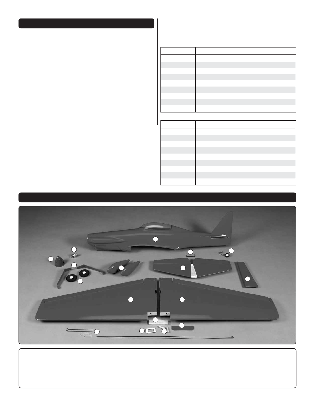
KIT CONTENTS
1
11
12
9
10
17
8
2
13
14
15
7
4
3
16
6
5
1. Fuselage
2. Right Wing Half
3. Left Wing Half
4. Horizontal Stabilizer
5. Rudder
6. Tail Wheel
7. Elevator Joiner Wire
8. Wheel Pants
9. Main Landing Gear
10. Main Wheels
11. Prop Adapter
12. Spinner
5
13. Wing Joiner
14. Aileron Servo Tray
15. Wing Dowels
16. Wing Bolt Plate
17. Pushrods
Page 6
PREPARATIONS
1. If you have not done so already, remove the major
❏
parts of the kit from the box and inspect for damage. If any
parts are damaged or missing, contact Product Support at
the address or telephone number listed in the “Kit Inspection”
section on page 4.
2. Check the covering on the wing, stabilizer and rudder.
❏
Use a covering iron with a covering sock on medium heat to
tighten the covering if necessary. Apply pressure over sheeted
areas to thoroughly bond the covering to the wood.
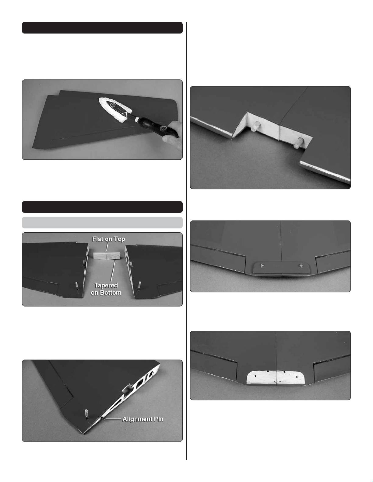
ASSEMBLE THE WING
3. Mix together ½ oz. [15cc] of 30-minute epoxy. Coat the
❏
inside of wing joiner cavity in both of the wing halves. Apply
epoxy to half of the wing joiner and insert it into one of the
wing halves. Apply epoxy to the other half of the wing joiner
and the root rib of both wing halves. Join the second wing
half to the fi rst. Wipe off any excess epoxy with a paper towel
dampened with denatured alcohol. Hold the two wing halves
together with masking tape until the epoxy has cured.
4. Insert the two ¼" × 1" [6 × 25 mm] wood wing dowels
❏
in the leading edge of the wing. Glue the wing dowels to the
wing with thin CA glue.
Join the Wing Halves
1. Test fi t the hardwood wing joiner in the two wing halves.
❏
Note that one edge of the wing joiner is fl at and the other edge
is tapered. The fl at edge is positioned towards the top of the
wing. With the wing joiner properly installed both wing tips
should be off of the table. Check that there is no gap between
the two wing halves at the wing root.
5. Remove the covering from the two wing bolt holes in
❏
the wing and the wing bolt plate. Position the wing bolt plate
on the bottom of the wing and insert the two 3×18mm wing
bolts to hold it in position.
2. Insert the 3 × 15mm alignment pin half way into the root
❏
rib of one wing half. Use thin CA to glue it in position.
6. Use a fi ne line marker to mark the outline of the wing bolt
❏
plate on the bottom of the wing. Remove the wing bolt plate.
Using a sharp hobby knife cut and remove the covering from
the wing, inside the outline of the wing bolt plate. Do not cut
the balsa wing sheeting.
7. Glue the wing bolt plate to the bottom of the wing using
❏
the wing bolts to align the wing bolt plate with the wing.
6
Page 7

ASSEMBLE THE FUSELAGE
Install the Main Landing Gear
3. Position the right wheel pant over the wheel and
❏ ❏
secure it to the main landing gear with two 2 × 5 mm self
tapping screws.
1. Insert a 2mm axle through the right main landing
❏ ❏
gear. Secure the axle to the landing gear with a 4 mm lock
nut. Note: the front of the main landing gear sweeps forward.
2. Install a 2 mm wheel collar on the axle, then the foam
❏ ❏
main wheel, followed by a second 2 mm wheel collar. Apply
a drop of thread locker on the 3mm set screws and secure
the wheel collars on the axle with the set screws.
4. Attach the main landing gear to the fuselage with
❏ ❏
three 2.5×8mm self tapping screws.
5. Repeat steps 1–4 for the left main landing gear.
❏
Install the Stabilizer
1. Attach the wing to the fuselage with two 3 ×18 mm wing
❏
bolts and two 3mm fl at washers.
7
Page 8

2. Center the horizontal stabilizer in the slot in the fuselage.
❏
Stand back and look at the stab in relation to the wing. The
stab should be parallel with the wing. If not, sand the stab
saddle until the stab and wings are aligned.
HOW TO CUT COVERING FROM BALSA
Use a soldering iron to cut the covering from the stabilizer.
The tip of the soldering iron doesn’t have to be sharp, but
a fi ne-tip does work best. Allow the iron to heat fully.
Use a straightedge to guide the soldering iron at a rate that
will just melt the covering and not burn into the wood. The
hotter the soldering iron, the faster it must travel to melt a
fi ne cut. Peel off the covering.
3. Measure the distance from the tip of the stab to the
❏
center of the fuselage. Adjust the position of the stab until
they are equal.
4. Using a fi ne-point felt-tip pen, mark the outline of the
❏
fuselage on the top and the bottom of the stab.
5. Cut the covering on the top and bottom of the stab
❏
inside the line you have drawn. Use care to cut onl y into the
covering and not into the wood.
6. Wipe away the lines you drew. Insert the elevator joiner
❏
wire in the notch at the back of the stab saddle. Use epoxy to
glue the stab in place, being careful that the stab is properly
aligned. Wipe off any excess epoxy from the stab and fuselage
with a paper towel dampened with denatured alcohol. Recheck
that the stab is still aligned.
You can now remove the wings and continue with the assembly
of the fuselage.
8
Page 9

Install the Elevators and Rudder
Temporary Pin
to Keep Hinge
Centered
4. Attach the tail gear to the bottom of the fuselage with
❏
two 2mm self tapping screws.
5. As with the elevators, insert pins into the center of the
❏
hinges and install the hinges in the rudder. Insert the tail gear
wire in the rudder and check the fi t of the rudder on the fi n.
1. Test fi t the elevators to the horizontal stabilizer with the
❏
elevator joiner wire in each elevator half and six 10× 15mm
CA hinges. If the hinges don’t remain centered, stick a pin
through the middle of the hinge to hold it in position. Check that
both elevator halves are aligned. If not, remove the elevators
and while holding one leg of the elevator joiner wire, slightly
bend the other. Reinstall the elevator halves and check again.
2. Coat the inside of the two elevator joiner wire holes and
❏
the ends of the elevator joiner wire with 30-minute epoxy.
Install the two elevator halves and remove any pins you may
have inserted into the hinges. Adjust the elevators so there is
a small gap between the LE of the elevators and the horizontal
stabilizer. The gap should be small, just enough to see light
through or to slip a piece of paper through.
3. Apply four drops of thin CA to the top and bottom of each
❏
hinge. Allow the CA to wick along the hinge. Do not use CA
accelerator. After the CA has fully hardened, test the hinges
by pulling on the elevator.
6. Coat the inside of the tail gear wire hole and the end
❏
of the tail gear wire with 30-minute epoxy. Install the rudder
on the fi n and remove the pins. Apply four drops of thin CA
to the hinges.
7. Use a 3mm set screw to secure the 2mm wheel collar
❏
on the tail wheel wire.
Install the Motor
The Cosmic Wind EP has been designed to use the ElectriFly
RimFire .10 Outrunner Brushless motor. If you will be installing
a different motor, you may need to modify the plywood motor
plate in the front of the fuselage.
9
Page 10

1. Remove the brass wheel collar from the RimFire .10 motor.
❏
2. Install the RimFire .10 motor using the four 3×9mm
❏
machine screws and 3mm fl at washers. Before installing each
screw, apply a drop of threadlocker to the threads of the screw.
Make sure the motor is centered on the plywood motor mount.
4. Use adhesive backed hook and loop material to mount
❏
the receiver to the side of the fuselage. Tape the two antennas
to the sides of fuselage. If using a 72 MHz receiver, route the
antenna out the cooling exit holes and tape it to the bottom
of the fuselage.
INSTALL THE RADIO SYSTEM
Install the Elevator Servo
1. Insert one of the long 1mm wire pushrods in the left
❏
pushrod tube so that the Z-bend is at the aft end of the fuselage.
3. Connect the ESC to the motor. The ESC can be attached
❏
to the side of the fuselage with adhesive backed hook and
loop material.
2. Use a sharp hobby knife to remove the backplate from
❏
the large nylon control horn. Insert the elevator pushrod
wire in the outer most hole of the control horn.
10
Page 11

3. Using the elevator pushrod wire, position the control horn
❏
so that the four pushrod holes are in line with the elevator hinge
line. Mark the location of the mounting holes onto the elevator.
Drill a 3/32" [2.5 mm] hole on the marks, drilling through the
elevator. Attach the control horn to the elevator using two
2-56 × 1/2" [12mm] machine screws and the control horn
back plate. Remove the screws and apply a couple of drops
of thin CA to both holes to harden the wood. Then, reinstall
the control horn.
4. Connect a servo to the elevator output on the receiver.
❏
Switch on the receiver and transmitter and center the elevator
trims. Install a servo arm on the servo so that it is perpendicular
to the centerline of the servo.
6. Apply a drop of threadlocker to two cap screws and install
❏
them into two wheel collars. Slide the two wheel collars over
the elevator pushrod.
5. Position the elevator servo in the servo tray so that the
❏
hole ¼" (7mm) from the center of the servo arm is inline with
the pushrod wire. The servos can either be glued to the servo
tray with medium CA or attached with 2 × 6mm self tapping
screws. The screws do not require a pilot hole; just thread
them into the plywood tray.
7. Enlarge the hole in the servo arm with a #60 or 3/64"
❏
[1mm] drill bit. Insert the Z-bend of a 1 × 25 mm pushrod into
the hole ¼" (7mm) from the center of the elevator servo arm.
Slide the wheel collars over the two pushrods, positioning
them so that they are close to the ends of the two pushrods.
Tighten the cap screws against the pushrods.
8. Switch your radio system on and center the servo arm
❏
and elevators. Tighten the cap screws against the pushrods.
11
Page 12

Install the Rudder Servo
2. Glue the aileron servo tray over the aileron servo opening.
❏
3. Remove the rubber aileron torque rod thread protectors.
❏
Thread an aileron torque rod horn on to both aileron torque
rods so that the threads are fl ush with the top of the torque
rod horns. Adjust the horns so that both of them are the same
distance from the wing.
1. Install the rudder servo following the same procedure
❏
used to install the elevator servo. Note: Use the small nylon
control horn on the rudder.
Install the Aileron Servo
1. Place the aileron servo tray over the aileron servo
❏
opening in the top of the wing. Use a fi ne tip marker to mark
the outline of the aileron tray on the top of the wing. Remove
the tray and use a sharp hobby knife to remove the covering
from inside the marks. Be careful not to cut the balsa sheeting.
4. Attach the aileron servo to the servo tray either with glue
❏
or 2 × 6mm self tapping screws.
5. Insert the Z-bend of the 1 × 70 mm aileron pushrod
❏
wires in the two aileron torque rod horns.
12
Page 13

6. Apply a drop of threadlocker to the threads of four cap
❏
screws. Thread the cap screws into four wheel collars. Slide
the wheel collars over the aileron pushrods. Insert the two 1 ×
25 mm pushrods 4mm from the center of the servo arm. Slide
the wheel collars over the 1 × 25 mm pushrods.
7. Center the aileron servo arm and the ailerons. Tighten the
❏
cap screws against the pushrods at the end of the pushrods.
2. Cut and attach several pieces of the included adhesive
❏
backed hook or loop material to the top of the battery tray.
Attach the opposite piece of the hook and loop material to
the back of your fl ight battery.
Install the Canopy
1. For our model we used the head from the Williams
❏
Brothers 1/6 Scale Sportsman Pilot #18400 [WBRQ1140].
The pilot head had to be trimmed just under the nose to fi t
under the canopy.
FINIS H THE MODEL
Install the Battery Straps
1. Insert the piece of hook material in one of the slots of
❏
the battery tray. Insert the loop material in the opposite slot.
Press the hook and loop material together under the battery
tray to make a battery strap.
2. Clean the cockpit surface with denatured alcohol
❏
and a clean paper towel. Glue the pilot head in the cockpit,
approximately 3" [76mm] from the back of the cockpit.
13
Page 14

3. Clean the inside of the canopy with soap and water
FULL THROTTLE
RUDDER
MOVES RIGHT
ELEVATOR MOVES DOWN
RIGHT AILERON MOVES UP
LEFT AILERON MOVES DOWN
4-CHANNEL RADIO SETUP (Standard Mode 2)
❏
and dry thoroughly. Glue the canopy to the fuselage with
canopy glue such as Pacer Technology’s PT56 Canopy Glue
[PAAR3300].
Apply the Decals
The box photographs show the location of the decals on the
airplane. Refer to the box for the exact placement of the decals.
The following tips may be useful for applying them.
1. Use scissors or a sharp hobby knife to cut the decals
❏
from the sheet.
2. Be certain the model is clean and free from oily fi ngerprints
❏
and dust. Prepare a dishpan or small bucket with a mixture
of liquid dish soap and warm water—about one teaspoon of
soap per gallon of water. Submerse the decal in the soap and
water and peel off the paper backing. Note: Even though the
decals have a “sticky-back” and are not the water transfer type,
submersing them in soap & water allows accurate positioning
and reduces air bubbles underneath.
3. Position decals on the model. Holding the decal down,
❏
use a paper towel to wipe most of the water away.
3. Make certain that the control surfaces respond in the
❏
correct direction as shown in the diagram. If any of the controls
respond in the wrong direction, use the servo reversing in the
transmitter to reverse the servos connected to those controls.
Be certain the control surfaces have remained centered. Adjust
if necessary.
Set the Control Throws
To ensure a successful fi rst fl ight, set up your Cosmic Wind
EP according to the control throws specifi ed in this manual.
The throws have been determined through actual fl ight
testing and accurate record-keeping, allowing the model
to perform in the manner in which it was intended.
1. Use a box or something similar to prop up the bottom of
❏
the fuselage so the horizontal stabilizer and wing will be level.
2. Measure the high rate elevator throw fi rst. Hold a ruler
❏
vertically on your workbench against the widest part (front to
back) of the trailing edge of the elevator. Note the measurement
on the ruler.
4. Use a piece of soft balsa or something similar to squeegee
❏
remaining water from under the decal. Apply the rest of the
decals the same way.
GET TH E MODEL READY TO FLY
Check the Control Directions
1. Turn on the transmitter and receiver and center the trims.
❏
If necessary, remove the servo arms from the servos and
reposition them so they are centered. Reinstall the screws
that hold on the servo arms.
2. With the transmitter and receiver still on, check all the
❏
control surfaces to see if they are centered. If necessary, loosen
the screw in the quick connector and center the control surfaces.
3. Move the elevator up with your transmitter and move the
❏
ruler forward so it will remain contacting the trailing edge. The
14
Page 15

distance the elevator moves up from center is the “up” elevator
throw. Measure the down elevator throw the same way.
4. Measure and set the low rate elevator throws and the
❏
high and low rate throws for the rest of the control surfaces
the same way.
If your radio does not have dual rates, we recommend setting
the throws at the high rate settings.
NOTE: The throws are measured at the widest part of the
elevators, rudder and ailerons.
These are the recommended control surface throws:
LOW RATE
Up & Down
1/8"
ELEVATORRUDDERAILERONS
[3mm] 4°
Right & Left
3/8"
[10 mm] 10°
Up & Down
1/8"
[3 mm] 7°
CAUTION: The throws appear to be small. However, the
model has been extensively fl own and tested to arrive at the
throws at which it fl ies best. Flying your model at these throws
will provide you with the greatest chance for successful fi rst
fl ights. Increasing the throws can cause the plane to be very
diffi cult to fl y.
HIGH RATE
Up & Down
1/4"
[6 mm] 8°
Right & Left
9/16"
[14 mm] 14°
Up & Down
3/16"
[5 mm] 11°
Install the Propeller
Insert the motor battery in the fuselage. Switch on the
transmitter and connect the motor battery to the ESC. While
securely holding the plane, slowly advance the throttle. The
motor should rotate counterclockwise when viewed from the
front. If it rotates the wrong direction, switch two of the three
motor wires.
2. Use a prop reamer or drill bit to enlarge the spinner back
❏
plate to fi t your motor’s prop adapter. Install the spinner back
plate, propeller with washer and prop nut and the spinner
cone. Secure the spinner cone to the back plate with two 2.5
× 7mm Sheet metal screws.
3. Insert a fl ight battery in the fuselage and use the hook and
❏
loop material to hold the battery in position. Do not connect
the battery to the ESC while balancing the model.
4. Install the battery hatch cover.
❏
Balance the Model (C.G.)
More than any other factor, the C.G. (balance point) can
have the greatest effect on how a model fl ies, and may
determine whether or not your fi rst fl ight will be successful.
If you value this model and wish to enjoy it for many fl ights,
DO NOT OVERLOOK THIS IMPORTANT PROCEDURE.
A model that is not properly balanced will be unstable and
possibly unfl yable.
At this stage the model should be in ready-to-fl y condition
with all of the systems in place including the motor, landing
gear, battery and the radio system.
1. Use a felt-tip pen or 1/8" [3mm]-wide tape to accurately
❏
mark the C.G. on the top of the wing at the side of the fuselage.
The C.G. is located 2–1/16" [52 mm] back from the leading
edge of the wing at the side of the fuselage.
1. Slide the collet type prop adapter on the motor shaft.
❏
This is where your model should balance for the fi rst fl ights.
Later, you may wish to experiment by shifting the C.G. up
to 3/16" [4.5 mm] forward or 3/16" [4.5mm] back to change
the fl ying characteristics. Moving the C.G. forward may
improve the smoothness and stability, but the model may
then require more speed for takeoff and make it more diffi cult
to slow for landing. Moving the C.G. aft makes the model
more maneuverable, but could also cause it to become too
diffi cult to control. In any case, start at the recommended
balance point and do not at any time balance the model
outside the specifi ed range.
15
Page 16

2-1/16" [52mm]
Charge the Batteries
Follow the battery charging instructions that came with your
radio control system to charge the batteries. You should always
charge your transmitter batteries the night before you go fl ying,
and at other times as recommended by the radio manufacturer.
CAUTION: Unless the instructions that came with your
radio system state differently, the initial charge on new
transmitter and receiver batteries should be done for 15
hours using the slow-charger that came with the radio
system. This will “condition” the batteries so that the next
charge may be done using the fast-charger of your choice.
If the initial charge is done with a fast-charger the batteries
may not reach their full capacity and you may be fl ying with
batteries that are only partially charged.
2. With the wing attached to the fuselage, and all parts of
❏
the model installed (ready to fl y), lift it at the balance point
you marked.
3. If the tail drops, the model is “tail heavy” and the battery
❏
pack must be shifted forward or weight must be added to
the nose to balance. If the nose drops, the model is “nose
heavy” and the battery pack must be shifted aft or weight
must be added to the tail to balance. If additional weight is
required, use Great Planes (GPMQ4485) “stick-on” lead. A
good place to add stick-on nose weight is next to the motor,
inside the fuselage (don’t attach weight to the battery hatch
cover—it is not intended to support weight). Begin by placing
incrementally increasing amounts of weight on the fuse until
the model balances. Once you have determined the amount
of weight required, it can be permanently attached.
4. IMPORTANT: If you found it necessary to add any weight,
❏
recheck the C.G. after the weight has been installed.
Balance the Model Laterally
1. With the wing level, have an assistant help you lift the
❏
model by the engine propeller shaft and the bottom of the
fuse under the TE of the fi n. Do this several times.
Balance the Propellers
Carefully balance your propeller and spare propellers before
you fl y. An unbalanced prop can be the single most signifi cant
cause of vibration that can damage your model. Not only
will motor mounting screws and bolts loosen, possibly with
disastrous effect, but vibration may also damage your radio
receiver and battery.
We use a Top Flite Precision Magnetic Prop Balancer
(TOPQ5700) in the workshop and keep a Great Planes
Fingertip Prop Balancer (GPMQ5000) in our fl ight box.
2. If one wing always drops when you lift the model, it means
❏
that side is heavy. Balance the airplane by adding weight to the
other wing tip. An airplane that has been laterally balanced
will track better in loops and other maneuvers.
PREFLIGHT
Identify Your Model
No matter if you fl y at an AMA sanctioned R/C club site or if
you fl y somewhere on your own, you should always have your
name, address, telephone number and AMA number on or
inside your model. It is required at all AMA R/C club fl ying sites
and AMA sanctioned fl ying events. Fill out the identifi cation
tag on page 19 and place it on or inside your model.
Range Check
Ground check the operational range of your radio before the
fi rst fl ight of the day. With the transmitter antenna collapsed
and the receiver and transmitter on, you should be able to walk
at least 100 feet away from the model and still have control.
Have an assistant stand by your model and, while you work the
controls, tell you what the control surfaces are doing. Repeat
this test with the motor running at various speeds with an
assistant holding the model, using hand signals to show you
what is happening. If the control surfaces do not respond
correctly, do not fl y! Find and correct the problem fi rst. Look
for loose servo connections or broken wires, corroded wires
on old servo connectors, poor solder joints in your battery
pack or a defective cell, or a damaged receiver crystal from
a previous crash. The problem may be the location of the
16
Page 17

antenna. The antenna should be as far away from the ESC
and battery as possible.
5) I will not fl y my model unless it is identifi ed with my name
and address or AMA number, on or in the model. Note: This
does not apply to models while being fl own indoors.
MOTOR SAFETY PR ECAUTIONS
Failure to follow these safety precautions may result
in severe injury to yourself and others.
● Get help from an experienced pilot when learning to operate
electric motors.
● Use safety glasses when running electric motors.
● Do not run the motor in an area of loose gravel or sand;
the propeller may throw such material in your face or eyes.
● Keep your face and body as well as all spectators away from
the plane of rotation of the propeller as you run the motor.
● Keep these items away from the prop: loose clothing, shirt
sleeves, ties, scarfs, long hair or loose objects such as
pencils or screwdrivers that may fall out of shirt or jacket
pockets into the prop.
● The motor gets hot! Do not touch it during or right after
operation.
● When working on your plane, remove the propeller if the
motor battery will be connected.
● Always remove the motor battery from the plane when
charging.
● Follow the charging instructions included with your charger
for charging LiPo batteries. LiPo batteries can cause serious
damage if misused.
Remember: Once the motor battery is plugged in, the motor
could start at any time. If you are working on the model,
remove the propeller.
7) I will not operate models with pyrotechnics (any device that
explodes, burns, or propels a projectile of any kind).
Radio Control
1) I will have completed a successful radio equipment ground
check before the fi rst fl ight of a new or repaired model.
2) I will not fl y my model aircraft in the presence of spectators
until I become a qualified flier, unless assisted by an
experienced helper.
3) At all fl ying sites a straight or curved line(s) must be
established in front of which all fl ying takes place with the
other side for spectators. Only personnel involved with fl ying
the aircraft are allowed at or in the front of the fl ight line.
Intentional fl ying behind the fl ight line is prohibited.
4) I will operate my model using only radio control frequencies
currently allowed by the Federal Communications Commission.
5) I will not kno wingly operate my model within three miles
of any pre-existing fl ying site except in accordance with
the frequency sharing agreement listed [in the complete
AMA Safety Code].
9) Under no circumstances may a pilot or other person touch
a powered model in fl ight; nor should any part of the model
other than the landing gear, intentionally touch the gr ound,
except while landing.
CHECK LIST
AMA SAFETY COD E
Read and abide by the following excerpts from the Academy
of Model Aeronautics Safety Code. For the complete Safety
Code refer to Model A viation magazine, the AMA web site or
the Code that came with your AMA license.
General
1) I will not fl y my model aircraft in sanctioned events, air shows,
or model fl ying demonstrations until it has been proven to be
airworthy by having been previously, successfully fl ight tested.
2) I will not fl y my model aircraft higher than approximately
400 feet within 3 miles of an airport without notifying the
airport operator. I will give right-of-way and avoid fl ying in the
proximity of full-scale aircraft. Where necessary, an observer
shall be utilized to supervise fl ying to avoid having models fl y
in the proximity of full-scale aircraft.
3) Where established, I will abide by the safety rules for the
fl ying site I use, and I will not willfully and deliberately fl y my
models in a careless, reckless and/or dangerous manner.
During the last few moments of preparation your mind may
be elsewhere anticipating the excitement of the fi rst fl ight.
Because of this, you may be more likely to overlook certain
checks and procedures that should be performed before the
model is fl own. To help avoid this, a check list is provided to
make sure these important areas are not overlooked. Many
are covered in the instruction manual, so where appropriate,
refer to the manual for complete instructions. Be sure to
check the items off as they are completed (that’s why it’s
called a check list!).
1. Check the C.G. according to the measurements provided
❏
in the manual.
2. Be certain the battery and receiver are securely mounted
❏
in the fuse.
3. If you are using a 72 MHz receiver, extend your receiver
❏
antenna and make sure it has a strain relief inside the fuselage
to keep tension off the solder joint inside the receiver.
4. Balance your model laterally as explained in the
❏
instructions.
17
Page 18

5. Use threadlocking compound to secure critical fasteners
❏
such as the motor screws, wheel collar SHC screws and quick
connectors, etc.
6. Add a drop of oil to the axles so the wheels will turn freely.
❏
7. Make sure all hinges are securely glued in place.
❏
8. Reinforce holes for wood screws with thin CA where
❏
appropriate (servo mounting screws, control horn screws, etc.).
9. Confi rm that all controls operate in the correct direction
❏
and the throws are set up according to the manual.
10. Make sure any servo extension cords you may have used
❏
do not interfere with other systems (servo arms, pushrods, etc.).
11. Balance your propeller (and spare propellers).
❏
12. Tighten the propeller nut and spinner.
❏
13. Place your name, address, AMA number and telephone
❏
number on or inside your model.
14. If you wish to photograph your model, do so before
❏
your fi rst fl ight.
Takeoff
Before you get ready to takeoff, see how the model handles
on the ground by doing a few practice runs at low speeds on
the runway. Hold “up” elevator to keep the tail wheel on the
ground. If necessary, adjust the tail wheel so the model will
roll straight down the runway. If you need to calm your nerves
before the maiden fl ight, bring the model back into the pits,
peak the battery and check all fasteners and control linkages
for peace of mind.
Remember to takeoff into the wind. When you’re ready, point
the model straight down the runway, hold a bit of up elevator
to keep the tail on the ground to maintain tail wheel steering,
then gradually advance the throttle. As the model gains
speed decrease up elevator allowing the tail to come off the
ground. One of the most important things to remember with
a tail dragger is to always be ready to apply right rudder to
counteract motor torque. Gain as much speed as your runway
and fl ying site will practically allow before gently applying up
elevator, lifting the model into the air. At this moment it is likely
that you will need to apply more right rudder to counteract
motor torque. Be smooth on the elevator stick, allowing the
model to establish a gentle climb to a safe altitude before
turning into the traffi c pattern.
15. Range check your radio when you get to the fl ying fi eld.
❏
FLYING
The Cosmic Wind EP is a great-fl ying model that fl ies smoothly
and predictably. The Cosmic Wind EP does not, however,
possess the self-recovery characteristics of a primary R/C
trainer and should be fl own only by experienced R/C pilots.
CAUTION (THIS APPLIES TO ALL R/C AIRPLANES): If,
while fl ying, you notice an alarming or unusual sound such
as a low-pitched “buzz,” this may indicate control surface
fl utter. Flutter occurs when a control surface (such as an
aileron or elevator) or a fl ying surface (such as a wing or
stab) rapidly vibrates up and down (thus causing the noise).
In extreme cases, if not detected immediately, fl utter can
actually cause the control surface to detach or the fl ying
surface to fail, thus causing loss of control followed by an
impending crash. The best thing to do when fl utter is detected
is to slow the model immediately by reducing power, then
land as soon as safely possible. Identify which surface
fl uttered (so the problem may be resolved) by checking all
the servo grommets for deterioration or signs of vibration.
Make certain all pushrod linkages are secure and free of
play. If it fl uttered once, under similar circumstances it will
probably fl utter again unless the problem is fi xed. Some
things which can cause fl utter are; Excessive hinge gap;
Not mounting control horns solidly; Poor fi t of clevis pin in
horn; Side-play of wire pushrods caused by large bends;
Excessive free play in servo gears; Insecure servo mounting;
and one of the most prevalent causes of fl utter; Flying an
over-powered model at excessive speeds.
Flight
For reassurance and to keep an eye on other traffi c, it is a
good idea to have an assistant on the fl ight line with you. Tell
him to remind you to throttle back once the plane gets to a
comfortable altitude.
Take it easy with the Cosmic Wind EP for the fi rst fl ight,
gradually getting acquainted with it as you gain confi dence.
Adjust the trims to maintain straight and level fl ight. After fl ying
around for a while, and while still at a safe altitude with plenty
of battery, practice slow fl ight and execute practice landing
approaches by reducing the throttle to see how the model
handles at slower speeds. Add power to see how she climbs
as well. Continue to fl y around, executing various maneuvers
and making mental notes (or having your assistant write them
down) of what trim or C.G. changes may be required to fi ne
tune the model so it fl ies the way you like. Mind your battery
power level, but use this fi rst fl ight to become familiar with your
model before landing. With most electric planes it is best to
have a timer set on your transmitter or a separate timer with
an alarm to alert you when the battery may be getting low.
This will require a few fl ights before determining the maximum
fl ight time you can achieve with the batteries. This will prevent
the downwind auto motor cutoff over the end of the fl ying fi eld.
Landing
To initiate a landing approach, lower the throttle while on the
downwind leg. Allow the nose of the model to pitch downward
to gradually bleed off altitude. Continue to lose altitude, but
maintain airspeed by keeping the nose down as you turn onto
the crosswind leg. Make your fi nal turn toward the runway (into
18
Page 19

the wind) keeping the nose down to maintain airspeed and
control. Level the attitude when the model reaches the runway
threshold, modulating the throttle as necessary to maintain
your glide path and airspeed. If you are going to overshoot,
smoothly advance the throttle (always ready on the right rudder
to counteract torque) and climb out to make another attempt.
When you’re ready to make your landing fl are and the model
is a foot or so off the deck, smoothly increase up elevator until
it gently touches down. Once the model is on the runway and
has lost fl ying speed, hold up elevator to place the tail on the
ground, regaining tail wheel control.
One fi nal note about fl ying your model. Have a goal or fl ight
plan in mind for every fl ight. This can be learning a new
maneuver(s), improving a maneuver(s) you already know,
or learning how the model behaves in certain conditions
(such as on high or low rates). This is not necessarily to
improve your skills (though it is never a bad idea!), but more
importantly so you do not surprise yourself by impulsively
attempting a maneuver and suddenly fi nding that you’ve run
out of time, altitude or airspeed. Every maneuver should be
deliberate, not impulsive. For example, if you’re going to do a
loop, check your altitude, mind the wind direction (anticipating
rudder corrections that will be required to maintain heading),
remember to throttle back at the top, and make certain you
are on the desired rates (high/low rates). A fl ight plan greatly
reduces the chances of crashing your model just because
of poor planning and impulsive moves. Remember to think.
Have a ball! But always stay in control
and fl y in a safe manner.
GOOD LUCK AND GREAT FLYING!
This model belongs to:
Name
Address
City, State, Zip
Phone Number
AMA Number
19
Page 20

 Loading...