

Page 1
SPECIFICATIONS
INSTRUCTION MANUAL
Wingspan: 31 in [785mm]
Wing Area: 112 in
Wing Loading: 21.9–23.1 oz/ft
Length: 24.5 in [620mm]
2
[7.2 dm2]
2
[67–70 g/dm2]
Motor, ESC, Battery: 24-33-3180kV Ammo inrunner,
WARRANTY
Great Planes® Model Manufacturing Co. guarantees this kit to
be free from defects in both material and workmanship at the
date of purchase. This warranty does not cover any component
parts damaged by use or modification. In no case shall Great
Planes’ liability exceed the original cost of the purchased kit.
Further, Great Planes reserves the right to change or modify this
warranty without notice.
In that Great Planes has no control over the final assembly or
material used for final assembly, no liability shall be assumed nor
accepted for any damage resulting from the use by the user of
the final user-assembled product. By the act of using the
user-assembled product, the user accepts all resulting liability.
If the buyer is not prepared to accept the liability associated
with the use of this product, the buyer is advised to return
READ THROUGH THIS MANUAL BEFORE STARTING CONSTRUCTION. IT CONTAINS IMPORTANT
INSTRUCTIONS AND WARNINGS CONCERNING THE ASSEMBLY AND USE OF THIS MODEL.
Weight: 17–18 oz [480–510 g]
Radio: 3-channel, 2 nano servos, mini receiver
25A ESC, 1500mAh 11.1V 25C LiPo
this kit immediately in new and unused condition to the
place of purchase.
To make a warranty claim send the defective part or item to
Hobby Services at the address below:
Hobby Services
3002 N. Apollo Dr. Suite 1
Champaign IL 61822 USA
Include a letter stating your name, return shipping address, as
much contact information as possible (daytime telephone
number, fax number, e-mail address), a detailed description of
the problem and a photocopy of the purchase receipt. Upon
receipt of the package the problem will be evaluated as quickly
as possible.
Champaign, Illinois
(217) 398-8970, Ext 5
airsupport@greatplanes.com
Entire Contents © 2010 GPMA1805 Mnl
Page 2

TABLE OF CONTENTS
INTRODUCTION . . . . . . . . . . . . . . . . . . . . . . . . . . . . . . . .2
AMA. . . . . . . . . . . . . . . . . . . . . . . . . . . . . . . . . . . . . . .2
SAFETY PRECAUTIONS . . . . . . . . . . . . . . . . . . . . . . . . .2
DECISIONS YOU MUST MAKE. . . . . . . . . . . . . . . . . . . . .3
Motor, Battery and ESC. . . . . . . . . . . . . . . . . . . . . . . .3
Servos, Receiver . . . . . . . . . . . . . . . . . . . . . . . . . . . . .3
Propeller. . . . . . . . . . . . . . . . . . . . . . . . . . . . . . . . . . . .3
ADDITIONAL ITEMS REQUIRED . . . . . . . . . . . . . . . . . . .4
Battery Chargers . . . . . . . . . . . . . . . . . . . . . . . . . . . . .4
Adhesives and Building Supplies. . . . . . . . . . . . . . . . .4
Optional Supplies. . . . . . . . . . . . . . . . . . . . . . . . . . . . .4
KIT INSPECTION. . . . . . . . . . . . . . . . . . . . . . . . . . . . . . . .4
KIT CONTENTS. . . . . . . . . . . . . . . . . . . . . . . . . . . . . . . . .4
ORDERING REPLACEMENT PARTS . . . . . . . . . . . . . . . .5
ASSEMBLY INSTRUCTIONS . . . . . . . . . . . . . . . . . . . . . .5
Hook Up the Elevator. . . . . . . . . . . . . . . . . . . . . . . . . .5
Install the Motor . . . . . . . . . . . . . . . . . . . . . . . . . . . . . .7
Mount the Receiver . . . . . . . . . . . . . . . . . . . . . . . . . . .8
Mark the Balance Range . . . . . . . . . . . . . . . . . . . . . . .9
Hook Up the Ailerons. . . . . . . . . . . . . . . . . . . . . . . . . .9
Mount the Landing Skids . . . . . . . . . . . . . . . . . . . . . .10
Apply the decals. . . . . . . . . . . . . . . . . . . . . . . . . . . . .11
GET THE MODEL READY TO FLY . . . . . . . . . . . . . . . . .11
Set the Control Throws. . . . . . . . . . . . . . . . . . . . . . . .11
Balance the Model (C.G.). . . . . . . . . . . . . . . . . . . . . .12
Balance the Model Laterally. . . . . . . . . . . . . . . . . . . .13
PREFLIGHT. . . . . . . . . . . . . . . . . . . . . . . . . . . . . . . . . . .13
Identify Your Model. . . . . . . . . . . . . . . . . . . . . . . . . . .13
Charge the Batteries . . . . . . . . . . . . . . . . . . . . . . . . .13
AMA SAFETY CODE (excerpts) . . . . . . . . . . . . . . . . . . .13
General . . . . . . . . . . . . . . . . . . . . . . . . . . . . . . . . . . .13
Radio Control. . . . . . . . . . . . . . . . . . . . . . . . . . . . . . .13
CHECK LIST . . . . . . . . . . . . . . . . . . . . . . . . . . . . . . . . . .14
FLYING. . . . . . . . . . . . . . . . . . . . . . . . . . . . . . . . . . . . . . .14
Mount the Wing . . . . . . . . . . . . . . . . . . . . . . . . . . . . .14
Ground Check and Range Check . . . . . . . . . . . . . . .15
Hand-Launch . . . . . . . . . . . . . . . . . . . . . . . . . . . . . . .15
Flying . . . . . . . . . . . . . . . . . . . . . . . . . . . . . . . . . . . . .15
Landing . . . . . . . . . . . . . . . . . . . . . . . . . . . . . . . . . . .16
still breathe a sigh of relief after every landing, but you’ll
become addicted to the speed and be ready for the next
fl ight after you’ve calmed your nerves.
For the latest technical updates or manual corrections to
the Rifl e visit the Great Planes web site at www.greatplanes.
com. Open the “Airplanes” link, then select Rifl e ARF. If there
is new technical information or changes to this model a “tech
notice” box will appear in the upper left corner of the page.
Academy of Model Aeronautics
If you are not already a member of the AMA, please join!
The AMA is the governing body of model aviation and
membership provides liability insurance coverage, protects
modelers’ rights and interests and is required to fl y at most
R/C sites.
Academy of Model Aeronautics
5151 East Memorial Drive
Muncie, IN 47302-9252
Tele. (800) 435-9262
Fax (765) 741-0057
Or via the Internet at:
http://www.modelaircraft.org
IMPORTANT!!! Two of the most important things you can
do to preserve the radio controlled aircraft hobby are to
avoid fl ying near full-scale aircraft and avoid fl ying near or
over groups of people.
PROTECT YOUR MODEL, YOURSELF
& OTHERS… FOLLOW THESE
IMPORTANT SAFETY PRECAUTIONS
1. Your Rifl e should not be considered a toy, but rather a
sophisticated, working model that functions very much
like a full-size airplane. Because of its performance
capabilities, the Rifl e, if not assembled and operated
correctly, could possibly cause injury to yourself or
spectators and damage to property.
INTRODUCTION
Thank you for purchasing the Great Planes Rifl e ARF.
Prepare to be thrilled! Before fl ying your Rifl e make sure
you’ re really ready; get a good night’s sleep and do what you
can to optimize your reaction time and concentration level,
because the Rifl e’s small size and extreme speed can cause
it to get out of visual range within a few seconds! We’ve
clocked it at average speeds of 90mph, but in actuality it
seems like it’s going over 200! The Rifl e does fl y predictably
and smoothly, so TOC (Tournament of Champions) skills
are not required, but you still must be a competent pilot with
the ability to remain calm and react decisively when being
challenged. And even after you get used to your Rifl e, you’ll
2. You must assemble the model according to the
instructions. Do not alter or modify the model, as doing
so may result in an unsafe or unfl yable model. In a few
cases the instructions may differ slightly from the photos.
In those instances the written instructions should be
considered as correct.
3. You must take time to build straight, true and strong.
4. You must use an R/C radio system that is in good condition,
a correctly sized motor, and other components as specifi ed
in this instruction manual. All components must be correctly
installed so that the model operates correctly on the ground
and in the air. You must check the operation of the model
and all components before every fl ight.
2
Page 3

5. If you are not an experienced pilot or have not fl own this
type of model before, we recommend that you get the
assistance of an experienced pilot in your R/C club for
your fi rst fl ights. If you’re not a member of a club, your
local hobby shop has information about clubs in your area
whose membership includes experienced pilots.
6. While this kit has been fl ight tested to exceed normal use,
if the plane will be used for extremely high stress fl ying,
such as racing, or if a motor larger than recommended
is used, the modeler is responsible for taking steps
to reinforce the high stress points and/or substituting
hardware more suitable for the increased stress.
7. WARNING: The fuselage, wing and horizontal stabiliz er
included in this kit are made of fi berglass, the fi bers of
which may cause eye, skin and respiratory tract irritation.
Never blow into a part to remove fi berglass dust, as the
dust will blow back into your eyes. Always wear safety
goggles, a particle mask and rubber gloves when
grinding, drilling and sanding fi berglass parts. Vacuum
the parts and the work area thoroughly after working with
fi berglass parts.
We, as the kit manuf acturer, provide you with a top quality,
thoroughly tested kit and instructions, but ultimately the
quality and fl yability of your fi nished model depends
on how you build it; therefore, we cannot in any way
guarantee the performance of your completed model,
and no representations are expressed or implied as to the
performance or safety of your completed model.
Remember: Take your time and follo w the instructions to
end up with a well-built model that is straight and true.
❍ ElectriFly 11.1V (3S) 1300 mAh 25C Power
Series LiPo (GPMP0505)
is also suitable because it is only slightly less in capacity and
is also .5 oz [14g] lighter.
If purchasing several batteries for your Rifl e, it may be a
good idea to purchase at least one lighter battery, allowing
your Rifl e to be slightly more maneuverable and land slightly
slower which may be benefi cial at least for the fi rst fl ight.
Under “normal” fl ying conditions (mostly full throttle),
average fl ight times are approximately four minutes of
motor run time (with approximately one more minute for
multiple landing attempts).
The:
❍ Great Planes ElectriFly SS-25 25 Amp
brushless ESC (GPMM1820)
is also recommended.
Servos, Receiver
No unusual radio gear is required for the Rifl e, just a small
receiver and one elevator servo and aileron servo in the 1520 oz-in torque range that will fi t in the mounts.
Servos used in the prototypes for testing were both the:
DECISIONS YOU MUST MAKE
This is a partial list of items required to fi nish the Rifl e that
may require planning or decision making before starting
assembly. Order numbers are provided in parentheses.
Motor, Battery and ESC
The Rifl e was designed for and tested exclusively with the:
❍ ElectriFly Ammo™ 24-33-3180kV inrunner
brushless motor (GPMG5155)
This motor provided straight-and-level average speeds
of 90mph.
There are two different batteries suitable f or the Rifl e. Due to
its larger capacity the:
❍ ElectriFly 11.1V (3S) 1500mAh 25C Power
Series LiPo (GPMP0511)
❍ Great Planes ES50 Nano servos (GPMM1210)
and the
❍ Futaba® S3107 servos (FUTM0025).
Any mini 4-channel aircraft receiver will work. A Futaba 2.4GHz
R617FS FASST™ receiver (FUTL7627) was also used in the
prototypes and is illustrated in the instruction manual.
Propeller
The Rifl e was fl own exclusively with an:
❍ APC 4.75 x 4.75 Speed 400 electric propeller
(APCQ4910)
You should also have several spare propellers on-hand to
replace ones that break upon landing.
is preferred, but the:
3
Page 4
ADDITIONAL ITEMS REQUIRED
Battery Charger
A LiPo-capable battery charger and a power source for
•
the charger is required. One recommended charger is
the Great Planes ElectriFly TritonEQ™ AC/DC Charger
(GPMM3155). The TritonEQ can be powered either by
an AC or DC power source and features a built-in LiPo
cell balancer.
Another suitable LiPo battery charger is the Great Planes
•
PolyCharge4™ DC LiPo charger (GPMM3015). The
PolyCharge4 can charge up to four LiPo batteries at the
same time, but requires separate LiPo cell balancers, so
for each LiPo battery you wish to charge simultaneously
(up to 4), one Great Planes Equinox™ LiPo Cell Balancer
(GPMM3160) will be required. The Equinox comes with
2S and 3S charge adapters, so these will be suitable for
the batteries recommended for your Rifl e. Finally, the
PolyCharge4 does not have AC capability, so if wallcharging from home is a priority a separate A/C 12-Volt
power source must also be purchased. A suitable power
supply then for the PolyCharge4 is the Great Planes 12V
12A DC power supply (GPMP0901).
❍ 1/2 oz. [15g] Thin Pro™ CA (GPMR6001)
❍ CA applicator tips (HCAR3780)
❍ 2 oz. [59mL] spray CA activator (GPMR6035)
❍ Threadlocker thread locking cement (GPMR6060)
❍ Stick-on segmented lead weights (GPMQ4485)
❍ 1/16" [1.6mm] drill
Optional Supplies
❍ Du-Bro® double-sided tape (DUBQ3551—for
mounting ESC, receiver)
❍ Shoe Goo™ (DTXC2460—for securing servo wires)
❍ Great Planes Velcro® (GPMQ4480—for additional
batteries)
KIT INSPECTION
Before starting to build, take an inventory of this kit to make
sure it is complete, and inspect the parts to make sure they
are of acceptable quality . If any parts are missing or are not of
acceptable quality, or if you need assistance with assembly,
contact Product Support. When reporting defective or
missing parts, use the part names exactly as they are written
in the Kit Contents list.
Adhesives and Building Supplies
Other than common hobby tools this is the list of adhesives
and building supplies that are required to fi nish the Rifl e.
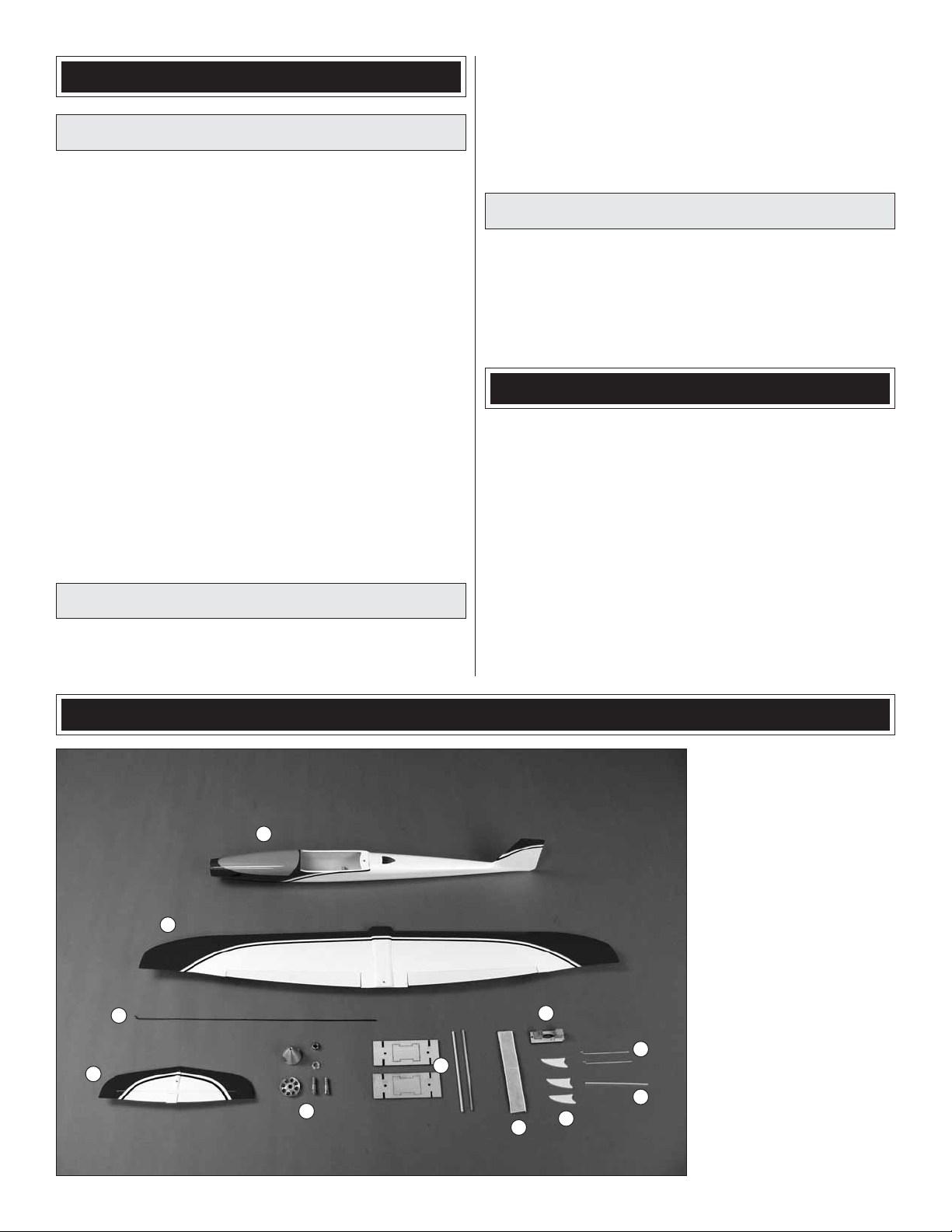
KIT CONTENTS
1
2
3
4
5
6
Great Planes Ph: (217) 398-8970, ext. 5
Product Support Fax: (217) 398-7721
3002 N Apollo Drive, Suite 1
Champaign, IL 61822
E-mail: airsupport@greatplanes.com
1. Fuselage
2. Wing
3. Elevator pushrod
4. Horizontal stabilizer
5. Spinner
(cone, back plate, shaft,
washer, nut, spare shaft)
6. Balancing stand
7. Adhesive-back
8
10
11
7
9
hook & loop material
8. Elevator servo mount
9. Landing skids
10. Aileron pushrods
11. Antenna guide tube
4
Page 5
ORDERING REPLACEMENT PARTS
ASSEMBLY INSTRUCTIONS
Replacement parts for the Great Planes Rifl e ARF are
available using the order n umbers in the Replacement Parts
List that follows. The fastest, most economical service can
be provided by your hobby dealer or mail-order company.
To locate a hobby dealer, visit the Great Planes web site
at www.greatplanes.com. Select “Where to Buy” in the
menu across the top of the page and follow the instructions
provided to locate a U.S., Canadian or International dealer.
Parts may also be ordered directly from Hobby Services by
calling (217) 398-0007, or via facsimile at (217) 398-7721,
but full retail prices and shipping and handling charges will
apply. Illinois and Nevada residents will also be charged
sales tax. If ordering via fax, include a Visa
number and expiration date for payment.
Mail parts orders and payments by personal check to:
Hobby Services
3002 N Apollo Drive, Suite 1
Champaign IL 61822
Be certain to specify the order number exactly as listed in
the Replacement Parts List. Payment by credit card or
personal check only; no C.O.D.
®
or MasterCard®
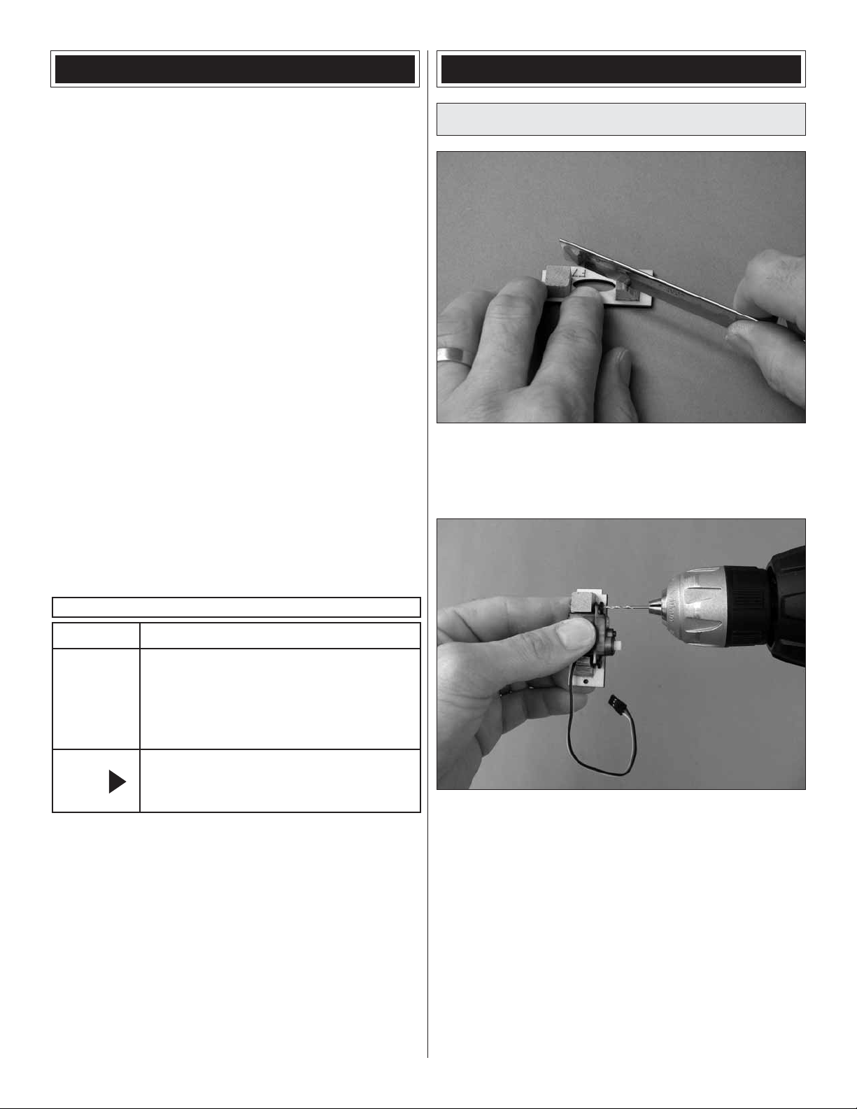
Hook Up the Elevator
1. Test fi t your elevator servo to the servo mount. If
❏
necessary, trim the mount to fi t the ser vo—it will probably
be necessary to trim a portion of one of the blocks to
accommodate the servo wire.
If additional assistance is required for any reason contact
Product Support by e-mail at productsupport@greatplanes.
com, or by telephone at (217) 398-8970.
REPLACEMENT PARTS LIST
Order No. Description
GPMA2720
GPMA2721
GPMA2722
GPMA2723
GPMA2724
NOTE
The stabilizer and wing incidences and engine thrust
•
angles have been factory-built into this model. However,
some technically-minded modelers may wish to check
these measurements anyway. To view this information
visit the web site at www.greatplanes.com and click on
“Technical Data.” Due to manufacturing tolerances which
will have little or no effect on the way your model will fl y,
please expect slight deviations between your model and
the published values.
Wing
Fuselage
Horizontal Stabilizer
Spinner Set
Decal Sheet
Full-size plans are not available.
You can download a copy of this
manual at www.greatplanes.com.
2. Place your servo in the mount and drill 1/16" [1.6mm]
❏
holes through the blocks for the mounting screws.
3. Mount the servo with the screws included with this kit
❏
(or the screws that came with your servo).
4. Remove the servo from the mount, add a few drops
❏
of thin CA to screw holes and allow to harden. Remount
the servo.
The servo has to be centered before mounting the servo arm,
so temporarily hook up the radio and center the servo as
described…
5
Page 6

Cut off the unused arms
Cut
5/16" [8mm]
ELEVATOR Servo Arm
5. Connect your ESC and ele vator servo to your receiver.
❏
Turn on your transmitter, center the trims and connect a
battery to the ESC so the servo will center. Temporarily fi t
a servo arm that has holes 5/16" [8mm] out from center to
the servo so it will be 90 degrees (this will be the longer two
of the four arms on the small servo arm that comes with the
Futaba and ElectriFly ES50 Nano servo). Take off the arm,
cut off the unused arms, then mount the servo arm to the
servo with the mounting screw.
the tab in the back of the mount into the former and holding
down the front with one of the 2mm x 10mm Phillips wood
screws included with this kit.
8. With the elevator servo centered, use fl at-nose pliers
❏
to bend the pushrod 1/8" [3mm] from the trailing edge of the
vertical stabilizer (fi n) where shown.
6. Connect the elevator pushrod to the elevator servo
❏
arm as shown.
7. Guide the elevator pushrod down through the guide
❏
tube in the fuselage and mount the elevator servo by keying
9. Connect one of the aluminum screw-lock connectors to
❏
farthest-in hole in the elevator control horn on the elevator.
10. Fit the ele vator pushrod into the screw-loc k connector
❏
and mount the horizontal stabilizer (stab) to the fi n with the
two 2mm x 8mm counter-sink Phillips fl at-head screws.
Note: Obviously, the stab must be securely mounted. While
6
Page 7

tightening the screws, make certain they are getting a good
“bite” into the fi n and that they can be tightened securely.
You may be tempted to permanently glue the stab into
position, but all of our rigorous testing proved that this was
not necessary as all of our prototypes depended upon the
screws only. If your screws don’t seem to get an adequate
bite, remove the screws, add a few drops of thin CA down
into the screw holes in the top of the fi n, allow to thoroughly
harden, and then remount the stab with the screws.
to thoroughly “rub” the strip down onto the bottom of the
fuselage. Apply a few drops of thin CA around the edges of
the strip to make sure it never comes up.
2. While y ou’ve got your hook & loop material out, attach
❏
a matching strip of the softer, “loop” side to your battery.
11. Temporarily connect the ser vo to your receiver and
❏
power the system up. With the servo and elevator centered
temporarily lock the pushrod to the screw-lock with a 2mm
screw. Use your transmitter to move the elevator. Make sure
it moves smoothly and that you can get the 3/16" [5mm]
(13°) of up and down elevator throw as specifi ed on page
12. Make any adjustments necessary to the bend in the wire
and cut off excess wire.
12. Once satisfi ed with the elevator movement, remove
❏
the screw , add a drop of threadlock er , reinstall the screw and
securely tighten.
Note: If for some reason you ever need to make another
elevator pushrod, use K&S .039" [1mm] music wire.
Install the Motor
3. Optional: Shortening the ESC wires will remove
❏
excess wire from the battery compartment, making it
easier to install and remove the battery. If you don’t feel like
shortening the wires you can just coil them up inside the
roof of the fuselage behind the motor. To shorten the wires,
remove the protective shrink tubing from the connectors
on the ESC, de solder the connectors, cut the wires so the
ends of the connectors will be 1" [25mm] from the end of the
ESC and re solder the connectors—don’t forget to apply new
pieces of shrink tubing.
1. Cut the rougher, “hook” side of the included hook &
❏
loop material to a length of 3" [75mm]. Apply the strip inside
the bottom of the fuselage just ahead of the front former.
Use the butt end of a small screwdriver or something similar
4. Connect the ESC to your motor and connect the
❏
ESC to the receiver. Turn on your transmitter and reverse
the throttle channel. Connect the battery to the ESC and
advance the throttle to make sure the motor is turning in
the correct direction. If the motor is not turning the correct
direction, switch any two motor/ESC wires with each other
to change the direction.
7
Page 8

5. Apply double-sided foam adhesive mounting tape or
❏
the adhesive hook & loop material to the ESC so it can be
mounted inside the top of the fuselage.
6. Drop the motor and ESC down into the fuselage so the
❏
motor shaft comes out the hole in the middle of the motor
mount. Note that the motor is mounted with the wires on top
so the ESC can also be mounted in the top of the fuselage,
leaving room for the battery on the bottom of the fuselage.
You should be able to stick your pinkey fi nger through one of
the openings in the side of the fuselage to rotate the motor
so the threaded screw holes align with the mounting holes
in the mount.
Mount the Receiver
Refer to these two photos while mounting the receiver.
1. Use the included, double-sided adhesive hook & loop
❏
material or double-sided foam adhesive mounting tape to
mount the receiver to the bottom of the fuselage—mount it as
far aft as you can (making room f or the antenna if necessary)
so it will not interfere with removal and installation of the
motor battery.
7. Mount the motor to the fi rewall with the 3mm screws
❏
that came with the motor and a drop of threadlocker. Stick
the ESC to the top of the fuselage.
Do not mount the propeller until instructed to do so after the
control throws have been set.
2. If using a Futaba FASST receiver with dual antennas
❏
(or another similar receiver with short antennas), use coarse
sandpaper to roughen the included 4" [100mm] antenna
tube so glue will adhere. Cut pieces from the tube to the
appropriate lengths and glue them to the inside of the
fuselage for securing the antennas.
3. If using a 72MHz receiver that has a longer, “whip”
❏
antenna, drill a small hole near the end of the fuselage
and guide the antenna down through the fuselage and out
the hole.
4. While you’re down inside the fuselage connect the
❏
elevator servo wire and the ESC wire to the receiver. We
8
Page 9

also used Shoe Goo to glue the ESC wire to the side of the
fuselage so it wouldn’t get in the way of the battery or aileron
servo. Other, non-permanent adhesive such as RTV silicone
would also be suitable for this.
Mark the Balance Range
Hook Up the Ailerons
1. Use a fi ne-point, felt-tip pen to mark the forward, mid
❏
(recommended) and aft C.G. locations on the bottom of both
sides of the wing 1/2" [13mm], 11/16" [17mm] and 7/8" [22mm]
back from the leading edges where they meet the fuselage.
2. Cut the C.G. Marking Guide from the back of the
❏
manual. Use the guide to draw lines across the marks you
made in the previous step.
Refer to this photo while hooking up the ailerons.
1. Test fit the aileron servo in the plywood servo
❏
mount on the bottom of the wing. If necessary, carefully
trim the mount to accommodate your servo, then mount
the servo with the included servo screws (or the screws
that came with your servo).
2. Temporarily remove the servo, harden the screw
❏
holes with a drop of thin CA, and allow to harden. Then,
remount the servo.
Screw-lock Connector
Torque Rod Horn
1/8" [3mm]
Aileron
Torque
Rod
3. Lay strips of vinyl tape across the balance lines where
❏
indicated by the arrows on the guide. These tape strips,
aligned with the sharpened suppor ts on the balance stand,
will keep the plane from slipping off the stand.
3. Mount a micro screw-lock connector to each torque
❏
rod horn with the retainers. Thread the horns onto the
torque rods until the tops of the horns are 1/8" [3mm] down
past the ends of the rods.
9
Page 10

9/16"
[15mm]
AILERON Servo Arm
4. Temporarily connect the aileron servo to the receiver
❏
and turn the system on to center the servo. Fit a servo arm
to the servo that will have holes 9/16" [15mm] apart and cut
off the unused arms.
Pushrod
Mount the Landing Skids
Don’t fl y your Rifl e without the landing skids. In addition
to protecting the underside, the landing skids perform
the important function of causing the plane to maintain a
straight-ahead trajectory on landing. Otherwise, it may spin
and pirouette, causing one of the wing tips to dig into the
ground and possibly cause damage.
NO YES
5. Connect the servo arm to the torque rods with the
❏
included pushrods. Center the ailerons and temporarily
tighten the screws in the screw-lock connectors to lock the
pushrods down. Make sure the ends of the pushrods do not
contact the sides of the torque rod horns. If the y do, shorten
the pushrods as necessary.
6. With the radio on and the ailerons centered, securely
❏
lock the pushrods down to the screw-lock connectors with
the screws and a drop of threadlocker.
7. Make sure the servo arm screw is in place. Turn on
❏
your transmitter and lower the throttle stick. Install and
connect the motor battery, then connect the aileron servo
wire to the receiver. Mount the wing to the fuselage with
the included 3mm x 10mm counter-sink fl at-head Allen
screw. Operate the ailerons to make sure the servo arm,
pushrods and torque rods are not interfering with anything
else down inside the fuselage (such as the elevator servo,
receiver or wiring).
Torque
Rod Horn
Make sure the end of the pushrod is not
contacting the side of the torque rod horn.
1. Find an assistant to hold the wing as shown in the top
❏
photo, with the trailing edge against your workbench. Use a
small builder’s square and a pencil to mark vertical lines on
the bottom of both wings 1-1/2" [40mm] from the tips.
8. Since you’re working on your ailerons and have them
❏
operating now, this would be a good time to set the aileron
throw as noted on page 12 (or, you could wait to set the
throws when you get to that part of the manual later).
2. Apply strips of masking tape 1/16" [1.5mm] on both
❏
sides of both lines.
10
Page 11

1. Use scissors or a shar p hobby knife to cut each decal
from the sheet.
2. Be certain the model is clean and free from oily fi ngerprints
and dust. Peel the fi rst decal you wish to apply from its
protective backing. Then, spray the back of the decal with
window cleaner.
3. Position the decal where desired and adjust for perf ection.
Use a piece of soft balsa or something similar to squeegee
the window cleaner from under the decal. Apply the rest of
the decals the same way.
3. Use medium-grit sandpaper to roughen the exposed
❏
paint between the tape. Hint: Wrap your sandpaper around
a 3/32" [2.4mm] sheet of balsa or something similar.
4. Remove the tape and clean off any residual tape glue.
❏
Note that base of the two wing skids is slightly curved to
match the airfoil shape of the wing while the fuselage skid
is fl at. Glue the wing skids to the bottom of the wing as
shown, starting with just a drop of thin CA. After the thin CA
has hardened, follow with another drop or two of thin CA or
medium CA. Allow to harden.
GET THE MODEL READY TO FLY
Set the Control Throws
T o ensure a successful fi rst fl ight, set up the Rifl e according
to the control throws specifi ed. The throws have been
determined through fl ight testing and record-keeping to
give the pilot enough control to quickly change directions
while at the same time not over controlling. If, after you
have become accustomed to the way the Rifl e fl ies, you
would like to change the throws to suit your taste, that
is fi ne. However, too much control throw could make the
model too responsive and diffi cult to control, so remember,
“more is not always better.”
Measure the high rate elevator throw fi rst…
1. Turn on the transmitter, install and connect the motor
❏
battery, plug in the aileron servo, and mount the wing.
5. Prepare the bottom of the fuselage the same way
❏
and glue the fuselage skid to the bottom of the fuselage 5"
[130mm] from the end, making certain it is centered.
Apply the Decals
The decals are applied “wet,” with window cleaner. This
allows for precise positioning and after you squeegee out
the window cleaner from under the decal there will be no air
bubbles (as there usually are when you apply them dry).
2. Holding a ruler vertically against the trailing edge of
❏
the middle of the elevator (the widest part), measure and
11
Page 12

compare the up and down throw to the specifi ed throw below.
If necessary, adjust the elevator throw by changing the ATVs
in your transmitter or by moving the pushrod on the servo arm.
If you’ve connected the pushrod to the servo arm as specifi ed
in the instructions the throws should be pretty close.
If your radio does not have dual rates, we recommend
setting the throws at the high rate settings.
NOTE: The throws are measured at the widest part of the
elevator and ailerons.
These are the recommended control surface throws:
HIGH RATE LOW RATE
2. At this stage your Rifl e should be in ready-to-fl y
❏
condition with all of the components in place including the
complete radio system, motor, propeller and spinner. Install
the motor battery and mount the wing.
3. Place your Rifl e on the balance stand with the
❏
pointed ends of the uprights on the middle balance lines
you marked earlier.
Up
ELEVATOR
AILERONS
3. Measure and set the low-rate elevator throw and the
❏
high and low-rate aileron throw.
3/16"
[5mm]
13 deg
Up
3/16"
[5mm]
11 deg
Down
3/16"
[5mm]
13 deg
Down
3/16"
[5mm]
11 deg
Up
3/32"
[2mm]
7 deg
Up
1/8"
[3mm]
7 deg
Down
3/32"
[2mm]
7 deg
Down
1/8"
[3mm]
7 deg
Balance the Model (C.G.)
More than any other factor, the C.G. (center of gravity/
balance point) can have the greatest effect on how a
model fl ies and could determine whether or not your fi rst
fl ight will be successful. If you value your model and wish
to enjoy it for many fl ights, DO NOT OVERLOOK THIS
IMPORTANT PROCEDURE. A model that is not properly
balanced may be unstable and possibly unfl yable.
This is where the Rifl e should balance for the fi rst fl ights.
Later, you may experiment by shifting the C.G. 3/16"
[4.8mm] forward or 3/16" [4.8mm] back to change the
fl ying characteristics. Moving the C.G. forw ard will improv e
stability, but the model will then land even faster. Moving
the C.G. aft will allow for slightly slower landing speeds,
but the model will then be more responsive. In any case,
start at the recommended balance point and do not at
any time balance the model outside the specifi ed range.
1. Assemble and glue together the plywood balance
❏
stand, but before gluing in the dowel uprights sand the
ends to a point.
4. If the model sits level it is perfectly balanced and
❏
is nearly ready to fl y. If it does not sit level ballast may be
required. Try moving your Rifl e forward or aft on the pointed
uprights just to see where it actually does balance. If it
balances within 1/16" [1.6mm] forward or aft of the middle
line (noting the recommended balance point) you could
probably fl y your Rifl e as balanced. But if it balances any
farther than that you should go ahead and balance it at the
recommended location. For certain, DO NOT fl y the Rifl e if
it balances outside the forward or aft lines. If any ballast is
required, it shouldn’t take much more than approximately 1/4
oz. [7g] on the tail or 1/2 oz. [14] in the nose.
12
Page 13

5. To fi nd out how much weight will be required, lay
❏
segments of Great Planes “stick-on” lead (GPMQ4485) on
the fuselage over the nose or tail where it will be attached.
Nose weight can be added inside the top of the fuselage just
behind the motor and tail weight can be stuck to the bottom
of the stab right next to where it attaches to the fuselage.
Once you have determined the amount of weight required, it
can be permanently attached.
Read and abide by the following excerpts from the Academy
of Model Aeronautics Safety Code. For the complete Safety
Code refer to Model A viation magazine, the AMA web site or
the Code that came with your AMA license.
AMA SAFETY CODE (EXCERPTS)
6. IMPORTANT: If you found it necessary to add any
❏
weight, recheck the C.G. after the weight has been installed.
Balance the Model Laterally
1. With the wing level, lift the model by the spinner and
❏
one fi nger under the tail at the very end of the fuselage. Do
this several times.
2. If one wing always drops, it means that side is heavy.
❏
Add stick-on weight to the bottom of the wing under the light
wing tip. An airplane that has been laterally balanced will
track better in loops and other maneuvers.
PREFLIGHT
Identify Your Model
No matter if you fl y at an AMA sanctioned R/C club site or
if you fl y somewhere on your own, you should always have
your name, address, telephone number and AMA number
on or inside your model. It is required at all AMA R/C club
fl ying sites and AMA sanctioned fl ying events. Fill out the
identifi cation tag on the decal sheet and place it on or inside
your model.
Charge the Battery
Follow the battery charging instructions that came with your
radio control system to charge the transmitter batteries.
You should always charge your transmitter and receiver
batteries the night before you go fl ying, and at other times
as recommended by the radio manufacturer.
CAUTION: Unless the instructions that came with your
radio system state differently, the initial charge on new
transmitter and receiver batteries should be done for 15
hours using the slow-charger that came with the radio
system. This will “condition” the batteries so that the next
charge may be done using the fast-charger of y our choice.
If the initial charge is done with a fast-charger the batteries
may not reach their full capacity and you may be fl ying
with batteries that are only partially charged.
General
1) I will not fl y my model aircraft in sanctioned events,
air shows, or model fl ying demonstrations until it has
been proven to be airworthy by having been previously,
successfully fl ight tested.
2) I will not fl y my model aircraft higher than approximately
400 feet within 3 miles of an airport without notifying the
airpor t operator. I will give right-of-way and avoid fl ying
in the proximity of full-scale aircraft. Where necessary,
an observer shall be utilized to supervise fl ying to avoid
having models fl y in the proximity of full-scale aircraft.
3) Where established, I will abide by the safety rules
for the flying site I use, and I will not willfully and
deliberately fly my models in a careless, reckless and/
or dangerous manner.
5) I will not fl y my model unless it is identifi ed with my name
and address or AMA number, on or in the model. Note:
This does not apply to models while being fl own indoors.
7) I will not operate models with pyrotechnics (any device
that explodes, burns, or propels a projectile of any kind).
Radio Control
1) I will have completed a successful radio equipment ground
check before the fi rst fl ight of a new or repaired model.
2) I will not fl y my model aircraft in the presence of spectators
until I become a qualifi ed fl ier, unless assisted by an
experienced helper.
3) At all fl ying sites a straight or curved line(s) must be
established in front of which all fl ying takes place with the
other side for spectators. Only personnel involved with
fl ying the aircraft are allowed at or in the front of the fl ight
line. Intentional fl ying behind the fl ight line is prohibited.
4) I will operate my model using only radio control frequencies
currently allowed by the Federal Communications
Commission.
5) I will not knowingly operate my model within three
miles of any pre-existing fl ying site except in
accordance with the frequency sharing agreement
listed [in the complete AMA Safety Code].
9) Under no circumstances may a pilot or other person
touch a powered model in fl ight; nor should any part of
the model other than the landing gear, intentionally
touch the ground, except while landing.
13
Page 14

CHECK LIST
During the last few moments of preparation your mind
may be elsewhere anticipating the excitement of the fi rst
fl ight. Because of this, you may be more likely to overlook
certain checks and procedures that should be performed
before the model is fl own. To help avoid this, a check list
is provided to make sure these important areas are not
overlooked. Many are covered in the instruction manual,
so where appropriate, refer to the manual for complete
instructions. Be sure to check the items off as they are
completed (that’s why it’s called a check list!).
1. Make certain you’ve set the C.G. and the control
❏
throws according to the measurements provided in
the manual.
2. Confi rm that the elevator and ailerons operate in the
❏
correct direction.
3. Make sure the serv o arms are secured with the screws
❏
that came with them.
4. Make sure the receiver antennas are oriented as
❏
specifi ed by the manufacturer.
5. Use threadlocking compound on the screws that lock
❏
the pushrods down to the screw-lock connectors.
6. Examine the elevator and ailerons to make sure the
❏
built-in hinges are intact.
7. Make sure the servo screw holes have been hardened
❏
with thin CA.
8. Place your name, address, AMA number and telephone
❏
number on or inside your model.
9. Range check your radio when y ou get to the fl ying fi eld.
❏
10. Before each fl ight closely inspect the elevator and
❏
aileron pushrod linkages to make sure they are secure.
FLYING
1. Advanced fl ying skills are required to fl y the Rifl e. It should
not be fl own by beginner or intermediate pilots.
2. The Rifl e will fl y at speeds near 100 mph and should be
fl own only at an approved AMA fl ying site.
3. The Rifl e can get out of sight quickly. Keep your focus on
the plane at all times.
When the Rifle is flying in front of you…
it’s easy to see!
However,
there may be moments during the turnaround when…
this is all you see.
Even experienced pilots must not underestimate the Rifl e’ s
extreme speed. Of course, it’s easy to lock onto the Rifl e
when it’s shooting by right out in front of you, but it takes
only a few seconds to get near the limits of your fl ight
pattern when it will appear extremely small and you will be
seeing it from a different perspective. This is when you can
lose orientation or visual contact altogether, so you must
see clearly and react decisively. For these reasons please
follow these pieces of advice—especially for your very
fi rst fl ights.
1. Do not fl y your Rifl e on a cloudy or overcast day. Poor
lighting and a gray bac kground make it e ven more diffi cult
to see. No matter what colors or markings your Rifl e has,
it will all disappear when it gets far away and just turns
into a black dot with no orientation cues.
2. Do not fl y when facing the sun. Wait for ideal light
conditions when the sun is at your back.
3. Do not try to fl y your Rifl e in confi ned fl ying sites.
While it is always possible (b ut not advisab le) to fl y above
obstructions, the Rifl e requires at least two or three times
the approach and landing space of regular sport models.
4. Do not fl y the Rifl e if for some reason, any of your senses
may hav e been compromised (from lac k of sleep, hunger,
dehydration, etc.). Y our vision, concentration and reaction
time must be optimum.
5. Ne ver tak e your e yes off the model – e ven while adjusting
the fl ight trims.
CAUTION: The Rifl e fl ies smoothly and predictably , b ut it is
small and fl ies EXTREMEL Y fast, so it is not a plane that should
be fl own by beginners or pilots with little experience. Further,
the Rifl e possesses no self-correcting tendencies whatso-ever—it waits for your inputs before changing directions.
Therefore, the Rifl e must be fl own only by experienced
pilots who are able to keenly detect what the model is
doing and decisively provide the correct contr ol inputs.
Mount the Wing
When ready to fl y, turn on your transmitter and make sure
the throttle stick is all the way down. Install and connect the
battery, plug the aileron servo wire into the receiver and
mount the wing.
Operate the controls to make sure everything is responding
correctly and smoothly.
14
Page 15

Ground Check and Range Check
Always perform an operational ground check of your radio
before the fi rst fl ight of the day following the manufacturer’s
instructions that came with your radio. This should be done
once with the motor off and once with the motor running
at various speeds. If the control surfaces do not respond
correctly, do not fl y! Find and correct the problem fi rst. Look
for loose servo connections or broken wires, corroded wires
on old servo connectors, or poor receiver antenna routing.
Hand-Launch
First, it’s a good idea to use a fl ight timer to alert you when
it’s time to land—it’ s alwa ys desirable to ha ve reserve battery
power because more than one landing attempt will probably
be necessary—especially for the fi rst fl ight. Throughout
testing we set our timer to four minutes (of motor run time).
This should provide an additional minute of run time for
landing approaches. For your fi rst fl ight it might even be a
good idea to set your timer to three minutes until you know
for certain how long your Rifl e will fl y.
The Rifl e can be launched by the pilot, but for the fi rst couple of
fl ights, and until the model has been trimmed for straight-and-
level fl ight, it is a good idea to have an assistant (with some
prior hand-launching experience) launch the Rifl e for you.
direction. Then, arm the motor and run it up for a second
to make sure it is making full power and sounds good. Make
sure your launch will be directly into any prevailing wind.
Inform your assistant of your intentions, make certain he
acknowledges, and then apply full throttle. Your assistant
should run for a few steps, then throw the plane into the air
at about a 30-degree angle, doing his best to level the wing
with the horizon.
Expect the Rifl e to descend briefl y before it gains enough
airspeed to establish a climb. Use the sticks to keep the
wings level.
At this point you’re in the clear and the model will climb as it
rapidly continues to gain speed—this will all happen within
two or three seconds!
Flying
Your fi rst priorities will be to get the Rifl e trimmed so it fl ies
straight-and-level when the sticks are neutral and to keep
it under control so you can keep it within visual range. If
you fi nd yourself getting “behind” the Rifl e, you can always
throttle back to 1/2 or ev en slightly less throttle. This will slow
the plane (a little) providing you with (slightly) more time to
think and react. You can also have your assistant adjust the
trims for you so you don't have to lift your fi ngers from the
control sticks.
Hold the model by the bottom of the fuselage under the wing.
As you should do before every fl ight, double-check that
the controls are responding properly and in the correct
Once you have the Rifl e trimmed you should be able to fl y
full throttle for extended periods, but it’s prudent to throttle
back (or cut the throttle altogether!) in turns so it doesn’t
get too far away. Fly “large”, keeping turns wide and smooth.
One good turn-around maneuver is to climb vertically, half
roll, throttle back, and then pull a 3/4 loop to upright level. Of
course, you can always “crank and bank” it too!
While at a high altitude with plenty of battery power, simulate
a landing approach by cutting the throttle and watching the
Rifl e glide. This will give you an indication of how it will land.
(Continued on page 16)
15
Page 16

Once over the flying field the Rifle prefers a long, shallow descent.
LONG
SHALLOW
Landing
The Rifl e doesn’t land like most other airplanes. It won’t fl y
slowly enough to make a proper fl air and you need to keep
the speed up to maintain aileron control authority to keep
the wings level.
When you’re ready to land, throttle back early on the
downwind leg and allow the Rifl e to bleed off some of its
airspeed. Before the Rifl e makes its crosswind turn cut the
throttle completely and allow it to continue its descent toward
the landing zone. It will still be considerably far out and y ou’ll
be looking at it almost head-on.
When the Rifl e is a foot or two [.3 - .6m] off the ground allow
it to continue a shallow descent with the fi rst priority to keep
the wings level. Continue to hold elevator until it eventually
catches the ground and skids to a stop—it usually doesn’t
skid very far—just a few yards [meters] or so.
If, at any point during your landing setup you realize you
are coming in too fast, simply throttle up, go around and
try again. And if you’re coming in too short, apply throttle to
stretch the landing.
After every landing closely inspect the model looking for an y
damage. Replace the propeller if necessary.
After a few fl ights you’ll have your Rifl e all trimmed out
for level fl ight and be executing perfect hand-launches,
adrenaline-pumping fl ights and smooth, routine landings
right at your feet.
One fi nal note about fl ying your Rifl e. Have a goal or fl ight
plan in mind for every fl ight. This can be learning a new
maneuver(s), improving a maneuver(s) you already know,
or learning how the model behaves in certain conditions
(such as on high or low rates). This is not necessarily to
improve your skills (though it is never a bad idea!), but more
importantly so you do not surprise yourself by impulsively
attempting a maneuver and suddenly fi nding that you’ve run
out of time, altitude or airspeed. Every maneuver should be
deliberate, not impulsive. F or example , if you’ re going to do a
loop, check y our altitude, mind the wind direction (anticipating
rudder corrections that will be required to maintain heading),
remember to throttle back at the top, and make certain you
are on the desired rates (high/low rates). A fl ight plan greatly
reduces the chances of crashing your model just because of
poor planning and impulsive moves. Remember to think.
Have a ball! But always stay in control
and fl y in a safe manner.
GOOD LUCK AND GREAT FLYING!
16
C.G. Marking Guide
Spare C.G. Marking Guide
This model belongs to:
Name
Address
City, State, Zip
Phone Number
AMA Number
 Loading...