

Page 1
SPECIFICATIONS
Wingspan:
Wing Area: 224 in
23 in
[585mm]
[14.4 dm2]
INSTRUCTION
MANUAL
Weight:
Length:
2
Wing
Loading:
32 oz [910 g]
30 in [760mm]
20.6 oz/ ft
[63 g/dm2]
2
Radio: 4-channel, elevon mixing,
2 micro servos
Motor,
ESC:
24-45-3790kV Ammo™,
35A ESC,
HyperFlow™ 56mm fan
WARRANTY
Great Planes® Model Manufacturing Co. guarantees this kit to
be free from defects in both material and workmanship at the
date of purchase. This warranty does not cover any component
parts damaged by use or modification. In no case shall Great
Planes’ liability exceed the original cost of the purchased kit.
Further, Great Planes reserves the right to change or modify this
warranty without notice.
In that Great Planes has no control over the final assembly or
material used for final assembly, no liability shall be assumed nor
accepted for any damage resulting from the use by the user of
the final user-assembled product. By the act of using the
user-assembled product, the user accepts all resulting liability.
If the buyer is not prepared to accept the liability associated
with the use of this product, the buyer is advised to return
READ THROUGH THIS MANUAL BEFORE STARTING CONSTRUCTION. IT CONTAINS IMPORTANT
INSTRUCTIONS AND WARNINGS CONCERNING THE ASSEMBLY AND USE OF THIS MODEL.
Entire Contents © 2012 Hobbico,® Inc. All rights reserved.
this kit immediately in new and unused condition to the
place of purchase.
To make a warranty claim send the defective part or item to
Hobby Services at the address below:
Hobby Services
3002 N. Apollo Dr. Suite 1
Champaign IL 61822 USA
Include a letter stating your name, return shipping address, as
much contact information as possible (daytime telephone
number, fax number, e-mail address), a detailed description of
the problem and a photocopy of the purchase receipt. Upon
receipt of the package the problem will be evaluated as quickly
as possible.
Champaign, Illinois
(217) 398-8970, Ext 5
airsupport@greatplanes.com
GPMA1802 Mnl
Page 2

TABLE OF CONTENTS
INTRODUCTION . . . . . . . . . . . . . . . . . . . . . . . . . . . . . . . . 2
Academy of Model Aeronautics . . . . . . . . . . . . . . . . . . 2
SAFETY PRECAUTIONS . . . . . . . . . . . . . . . . . . . . . . . . . 2
DECISIONS YOU MUST MAKE. . . . . . . . . . . . . . . . . . . . . 3
Radio Equipment . . . . . . . . . . . . . . . . . . . . . . . . . . . . . 3
Ducted Fan, Motor, Battery and ESC. . . . . . . . . . . . . . 3
Battery Charger . . . . . . . . . . . . . . . . . . . . . . . . . . . . . . 3
ADDITIONAL ITEMS REQUIRED . . . . . . . . . . . . . . . . . . . 3
Adhesives and Building Supplies. . . . . . . . . . . . . . . . . 3
KIT INSPECTION. . . . . . . . . . . . . . . . . . . . . . . . . . . . . . . . 4
ORDERING REPLACEMENT PARTS . . . . . . . . . . . . . . . . 4
KIT CONTENTS. . . . . . . . . . . . . . . . . . . . . . . . . . . . . . . . . 4
ASSEMBLY INSTRUCTIONS . . . . . . . . . . . . . . . . . . . . . . 5
Ducted Fan Assembly . . . . . . . . . . . . . . . . . . . . . . . . . 5
Mount the Fan in the Fuselage . . . . . . . . . . . . . . . . . . 8
ASSEMBLE THE WING . . . . . . . . . . . . . . . . . . . . . . . . . . 10
Mount the Wing Skids . . . . . . . . . . . . . . . . . . . . . . . . 13
Finish the Wings. . . . . . . . . . . . . . . . . . . . . . . . . . . . . 14
Mount the Wings to the Fuselage . . . . . . . . . . . . . . . 15
INTRODUCTION
Thank you for purchasing the Great Planes Phazer EDF
ARF. On the workbench, the Phazer’s main appeal is its
simplicity—with only two servos, “radio installation” and setup
are unusually simple and fast. And mounting the motor and
fan unit goes quickly too, so you’ll be off the workbench and
out at the fl ying fi eld in no time.
Out at the fl ying fi eld the Phazer’s appearance and fun fl ying
characteristics should easily win you over. It’s not “scary” fast,
but still fast considering its size, and capable of at least 90
mph straight-and-level. If you can do without the attention and
glory you get with bigger, more expensive jets (or if they’re out
of your budget!), you’ll have a ball fl ying your Phazer.
For the latest technical updates or manual corrections to the
Phazer visit the Great Planes web site at www.greatplanes.
com. Open the “Airplanes” link, then select Phazer ARF. If there
is new technical information or changes to this model a “tech
notice” box will appear in the upper left corner of the page.
FINAL ASSEMBLY . . . . . . . . . . . . . . . . . . . . . . . . . . . . . 15
Apply the Decals . . . . . . . . . . . . . . . . . . . . . . . . . . . . 16
GET THE MODEL READY TO FLY . . . . . . . . . . . . . . . . . 17
Set the Control Throws. . . . . . . . . . . . . . . . . . . . . . . . 18
PREFLIGHT . . . . . . . . . . . . . . . . . . . . . . . . . . . . . . . . . . . 19
Run-In the Fan . . . . . . . . . . . . . . . . . . . . . . . . . . . . . . 19
Identify Your Model. . . . . . . . . . . . . . . . . . . . . . . . . . . 20
Charge the Batteries . . . . . . . . . . . . . . . . . . . . . . . . . 20
Assemble the Bungee Launch . . . . . . . . . . . . . . . . . . 20
AMA SAFETY CODE. . . . . . . . . . . . . . . . . . . . . . . . . . . . 21
General . . . . . . . . . . . . . . . . . . . . . . . . . . . . . . . . . . . 21
Radio Control . . . . . . . . . . . . . . . . . . . . . . . . . . . . . . . 21
CHECK LIST . . . . . . . . . . . . . . . . . . . . . . . . . . . . . . . . . . 22
FLYING. . . . . . . . . . . . . . . . . . . . . . . . . . . . . . . . . . . . . . . 22
Ground Check and Range Check . . . . . . . . . . . . . . . 22
Set a Flight Timer. . . . . . . . . . . . . . . . . . . . . . . . . . . . 22
Launching . . . . . . . . . . . . . . . . . . . . . . . . . . . . . . . . . 22
Flying . . . . . . . . . . . . . . . . . . . . . . . . . . . . . . . . . . . . . 24
Landing . . . . . . . . . . . . . . . . . . . . . . . . . . . . . . . . . . . 24
IMPORTANT!!! Two of the most important things you can
do to preserve the radio controlled aircraft hobby are to avoid
fl ying near full-scale aircraft and avoid fl ying near or over
groups of people.
SAFETY PRECAUTIONS
Protect Your Model, Yourself & Others…
Follow These Important Safety Precautions
1. Your Phazer should not be considered a toy, but rather a
sophisticated, working model that functions very much like
a full-size airplane. Because of its performance capabilities,
the Phazer, if not assembled and operated correctly, could
possibly cause injury to yourself or spectators and damage
to property.
2. You must assemble the model according to the instructions.
Do not alter or modify the model, as doing so may result in an
unsafe or unfl yable model. In a few cases the instructions may
differ slightly from the photos. In those instances the written
instructions should be considered as correct.
Academy of Model Aeronautics
If you are not already a member of the AMA, please join! The
AMA is the governing body of model aviation and membership
provides liability insurance coverage, protects modelers’ rights
and interests and is required to fl y at most R/C sites.
Academy of Model Aeronautics
5151 East Memorial Drive
Muncie, IN 47302-9252
Tele. (800) 435-9262
Fax (765) 741-0057
Or via the Internet at: http://www.modelaircraft.org
3. You must take time to build straight, true and strong.
4. You must use an R/C radio system that is in good condition,
a correctly sized engine, and other components as specifi ed
in this instruction manual. All components must be correctly
installed so that the model operates correctly on the ground
and in the air. You must check the operation of the model and
all components before every fl ight.
5. If you are not an experienced pilot or have not fl own this type
of model before, we recommend that you get the assistance
of an experienced pilot in your R/C club for your fi rst fl ights.
If you’re not a member of a club, your local hobby shop has
information about clubs in your area whose membership
includes experienced pilots.
2
Page 3
6. While this kit has been fl ight tested to exceed normal use,
if the plane will be used for extremely high stress fl ying, such
as racing, or if an engine larger than one in the recommended
range is used, the modeler is responsible for taking steps to
reinforce the high stress points and/or substituting hardware
more suitable for the increased stress.
7. WARNING: The fuselage and tail cone adapter included in
this kit are made of fi berglass, the fi bers of which may cause
eye, skin and respiratory tract irritation. Never blow into a
part to remove fi berglass dust, as the dust will blow back into
your eyes. Always wear safety goggles, a particle mask and
rubber gloves when grinding, drilling and sanding fi berglass
parts. Vacuum the parts and the work area thoroughly after
working with fi berglass parts.
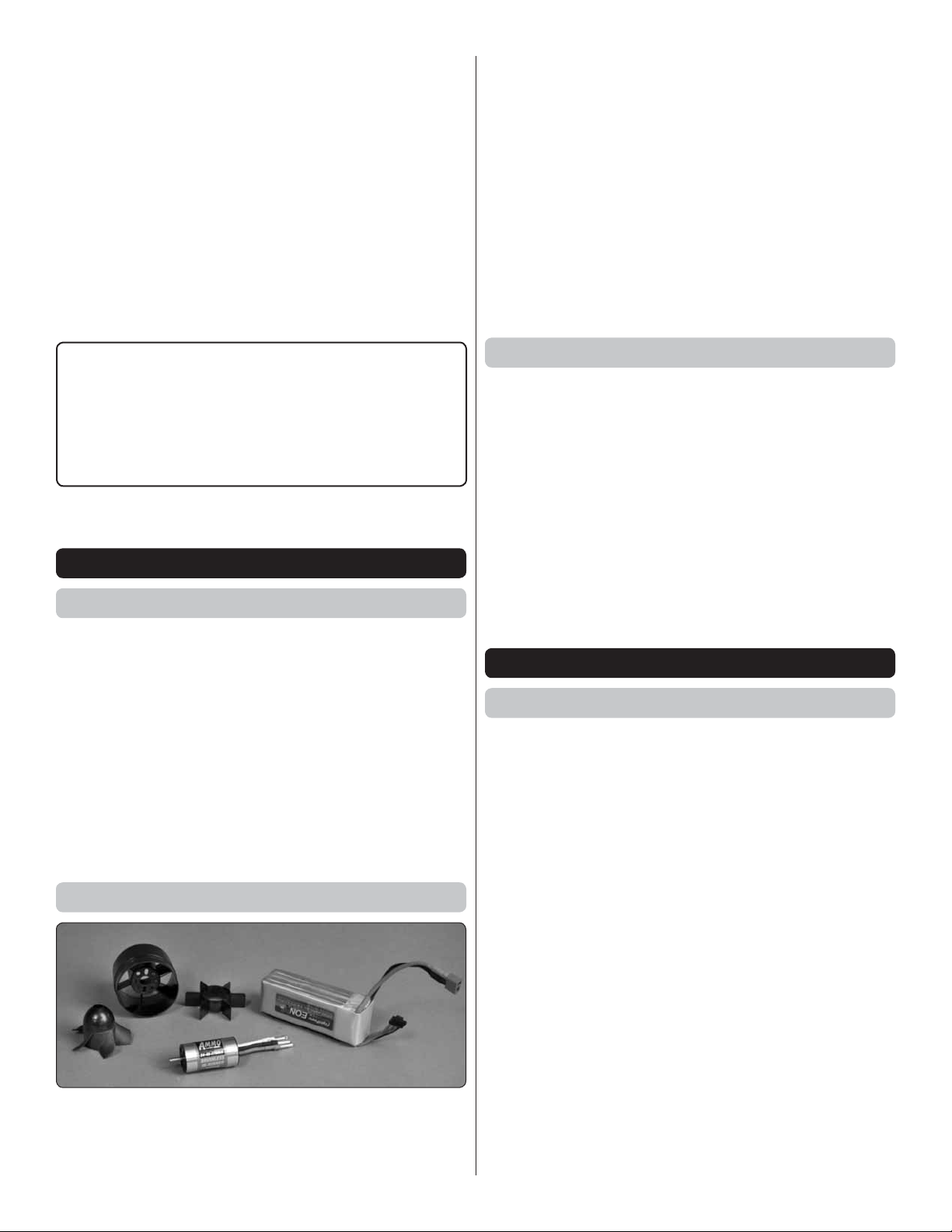
❍ The Phazer has also been designed to fl y with a 4S (14.8V)
LiPo battery in the 2200mAh, 30C range. Weighing 9.2 oz.
[260g] the Flight Power® 4S 2200mAh 30C EON-X™ LiPo
(FPWP6199) has a good combination of compact size,
reasonable weight and suitable power for fl ying the Phazer.
It can also be charged at up to 5C for quick turnaround
times to get you back into the air quickly!
Note: On a 4S 2200mAh 30C battery the Ammo motor/
HyperFlow fan unit draws approximately 32A on the ground
(static), about 30A in the air and consumes about 460mAh/
minute at full-throttle.
❍ The Great Planes ElectriFly SS (Silver Series) 35A brushless
ESC is also recommended. (GPMM1830)
We, as the kit manufacturer, provide you with a top quality,
thoroughly tested kit and instructions, but ultimately the
quality and fl yability of your fi nished model depends
on how you build it; therefore, we cannot in any way
guarantee the performance of your completed model, and
no representations are expressed or implied as to the
performance or safety of your completed model.
REMEMBER: Take your time and follow the instructions
to end up with a well-built model that is straight and true.
DECISIONS YOU MUST MAKE
Radio Equipment
Transmitter:
❍ Transmitter with elevon or ailevator mixing or any
other available programmable mix that can mix the
aileron and elevator channels.
Two micro servos in the 20 oz-in torque range:
❍ (2) Futaba® S3157 digital, micro, high-speed/torque
servos (FUTM0657)
Two 3" – 4" [75mm – 100mm] servo extension wires for
connecting the servos:
❍ (2) Futaba J-series 75mm extension slim leads
(FUTM3909)
Ducted Fan, Motor, Battery and ESC
Battery Charger
❍ A LiPo-capable battery charger is required. The Great
Planes ElectriFly Triton™ EQ AC/DC Charger (GPMM3155)
is recommended for a few reasons—it has built-in cell
balancing and an LCD screen that indicates individual cell
Voltage as well as fi nal charge capacity (which is valuable
for calculating fl ight times and other important data). The
Triton EQ can be powered either by a 110V AC power
source (wall plug-in) or external DC power source. For
fi eld-charging, the Great Planes 12V, 12A DC power supply
(GPMP0901) is suitable.
❍ For batteries that have a Deans connector, a Charge
Lead with banana plugs/Deans® Ultra® Male charge lead
(GPMM3148) is also required with the Triton EQ.
ADDITIONAL ITEMS REQUIRED
Adhesives and Building Supplies
Nothing extraordinary is required to assemble your Phazer.
Other than common hobby tools, here are the items required:
❍ 1/2 oz. Medium CA (GPMR6007)
❍ 1/2 oz. Thin CA (GPMR6001)
❍ CA applicator tips (HCAR3780)
❍ CA accelerator (GPMR6035)
❍ Threadlocker (GPMR6060)
❍ Great Planes Self Adhesive Lead Weights (GPMQ4485)
❍ Great Planes Pro™ 30-minute epoxy (GPMR6043) and
Top Flite® Microballoons (TOPR1090) for gluing on the
wings and installing the fan unit.
OR
❍ Zap Goo (PAAR3200) for gluing on the wings and
installing the fan unit.
❍ The Phazer has been designed to work with and includes
the Great Planes ElectriFly® HyperFlow™ 56mm ducted
fan system (GPMG3910) and the ElectriFly 24-45-3790kV
Ammo™ inrunner brushless motor (GPMG5185).
NOTE: Major wing repair or replacement will be easier if
they are not permanently attached. Zap Goo or RTV silicone
may be used for attaching the wings, yet can be removed
later if required.
Following are the colors of MonoKote® used on the Phazer:
❍ Jet White ❍ Missile Red ❍ Metallic Platinum
(TOPQ0204) (TOPQ0201) (TOPQ0408)
3
Page 4
KIT INSPECTION
Before starting to build, take an inventory of this kit to make
sure it is complete, and inspect the parts to make sure they
are of acceptable quality. If any parts are missing or are not
of acceptable quality, or if you need assistance with assembly,
contact Product Support. When reporting defective or missing
parts, use the part names exactly as they are written in the
Kit Contents list.
Great Planes Product Support
3002 N Apollo Drive, Suite 1 Ph: (217) 398-8970, ext. 5
Champaign, IL 61822 Fax: (217) 398-7721
E-mail: airsupport@greatplanes.com
Illinois and Nevada residents will also be charged sales tax. If
ordering via fax, include a Visa® or MasterCard® number and
expiration date for payment.
Mail parts orders Hobby Services
and payments by 3002 N Apollo Drive, Suite 1
personal check to: Champaign IL 61822
Be certain to specify the order number exactly as listed in the
Replacement Parts List. Payment by credit card or personal
check only; no C.O.D.
If additional assistance is required for any reason contact
Product Support by e-mail at productsupport@greatplanes.
com, or by telephone at (217) 398-8970.
ORDERING REPLACEMENT PARTS
Replacement parts for the Great Planes Phazer ARF are
available using the order numbers in the Replacement Parts
List that follows. The fastest, most economical service can be
provided by your hobby dealer or mail-order company.
To locate a hobby dealer, visit the Great Planes web site at
www.greatplanes.com. Select “Where to Buy” in the menu
across the top of the page and follow the instructions provided
to locate a U.S., Canadian or International dealer.
Parts may also be ordered directly from Hobby Services by
calling (217) 398-0007, or via facsimile at (217) 398-7721, but
full retail prices and shipping and handling charges will apply.
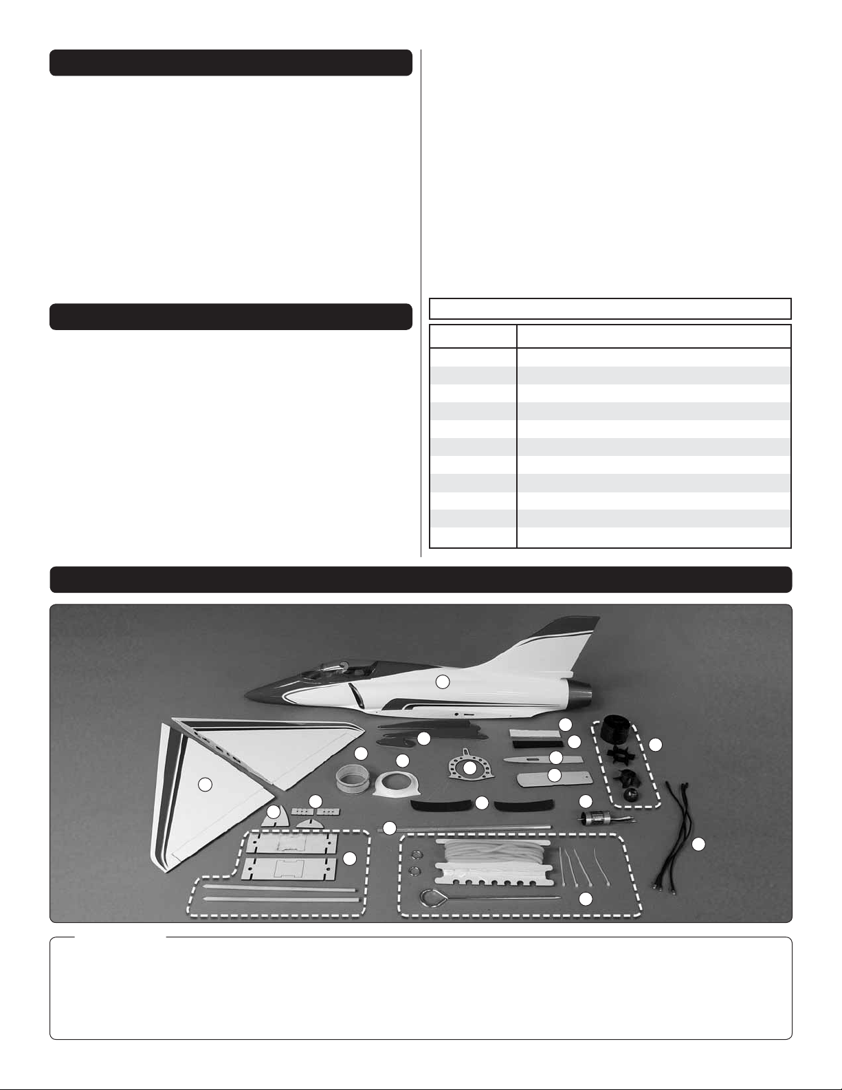
KIT CONTENTS
REPLACEMENT PARTS LIST
Order No. Description
GPMA4240
GPMA4241
GPMA4242
GPMA4243
GPMA4244
GPMA4245
GPMA4246
GPMA2885
GPMA2999
GPMG3910
GPMG5185
2
Fuselage
Wing
Canopy
Skid set
Flange/adapter set
Decal sheet
Wing joiner tube
Bungee launch set
Bungee hook/nut/washer
HyperFlow fan unit
24-45-3790 Ammo brushless motor
1
Kit Contents
1. Wing
2. Fuselage w/ Canopy
3. Skid Set
4. Cone Adapter
5. Front Housing Flange
4
18
19
12
17
6. Housing Mount
7. Fin Hole Cover
8. Battery Mount Plate
9. Velcro Battery Mount
10. Velcro Strap
3
5
6
11
11. Finger Grips
12. Wing Joiner Tube
13. Bungee Launch Kit
14. 24-45-3790 Ammo
Motor
4
9
10
7
8
14
13
16
15
15. Motor Extension Wires
16. HyperFlow Fan Unit
17. Balance Stand
18. Balance Gauge
19. C. G. Supports
Page 5
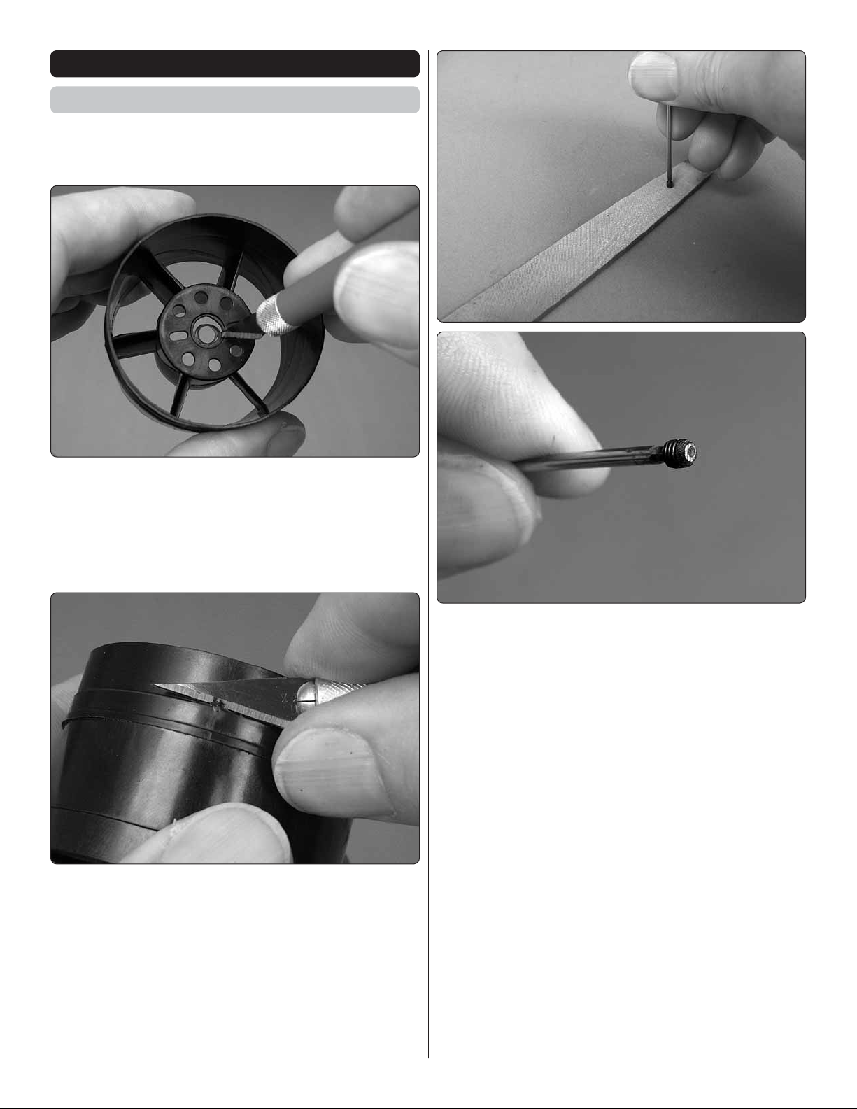
ASSEMBLY INSTRUCTIONS
Ducted Fan Assembly
Reference the separate HyperFlow instruction sheet as
necessary, but follow the instructions below for assembly/
installation into the Phazer.
1. Enlarge the hole in the fan housing to allow installation
❏
and removal of the motor without having to remove the brass
fan adapter.
2. As shown in the HyperFlow manual, trim the three
❏
alignment guides from inside the housing to accommodate
the motor.
4. Key one of the 3mm set screws (for fastening the brass
❏
fan rotor adapter to the motor shaft) onto a 1.5mm Allen
wrench—a basic “L” wrench is included if you don’t have one
of your own. Use a metal fi le to lightly fi le down the end of the
screw—it won’t take much—just a few passes to remove the
slightest fraction of an inch.
3. Trim any fl ashing from around the fan housing so the
❏
fi berglass cone adapter will fi t correctly.
5
Page 6
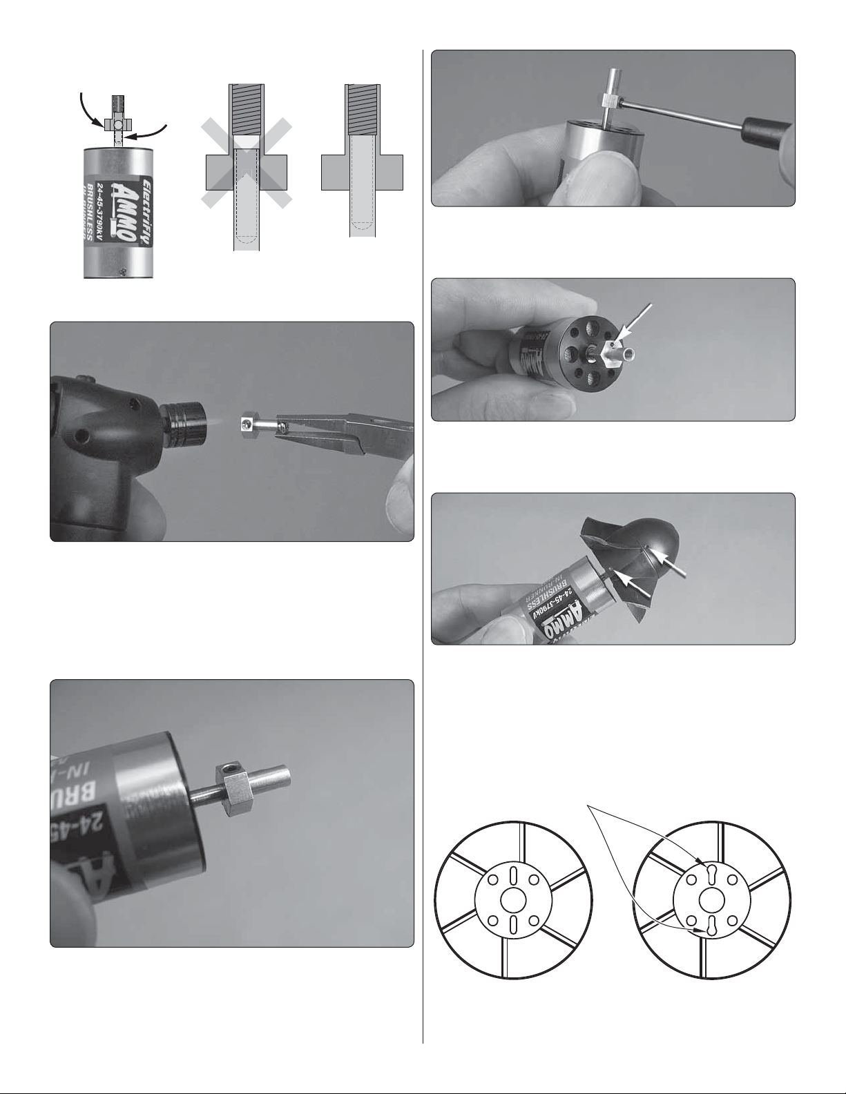
NO
FAN ROTOR
ADAPTER
(BRASS)
MOTOR
SHAFT
The adapter is
not all the way on.
The adapter is
all the way
down onto the
motor shaft up
to the threads.
YES
S
O
T
Enlarge to Fit
3 mm Screws
P
FLAT
7. Take out the set screws and lightly wet the threads with
❏
threadlocker. Then tighten them back into the adapter locking
it onto the shaft.
8. Use a felt-tip pen and/or drill a small dimple on top surface
❏
of the base of the adapter where shown. If necessary, this
will be used as an alignment cue for balancing the fan later.
❏
with the HyperFlow fan unit. Fit the adapter onto the motor
shaft with one of the set-screw holes in the adapter aligned
with the fl at spot on the shaft and make sure the adapter goes
all the way on up to the threads. If you can’t get the adapter
to go on all the way just by pressing it on, use a hobby torch
to heat the adapter fi rst.
5. Retrieve the brass fan rotor adapter that was packaged
9. Temporarily fi t the fan onto the adapter and the cone
❏
onto the fan. Use a 1/16" [1.6mm] twist drill, in a pin vise or
held in your fi ngers, to lightly dimple the side of the fan and
cone that align with the side of the adapter that also has the
dimple. Make sure all three dimples are in alignment. These
will all serve as temporary reference marks.
6. Test-fi t both set screws into the brass adapter on the
❏
shaft—the screw you fi led down goes into the hole that is not
over the fl at spot. Make sure the end of that screw is fl ush (or
slightly below) the surface of the adapter. If necessary, fi le
down the screw a little more.
10. Remove the cone and fan from the motor. Use a hobby
❏
knife to slightly enlarge the slots in the fan housing as shown
to accommodate the motor screws.
6
Page 7
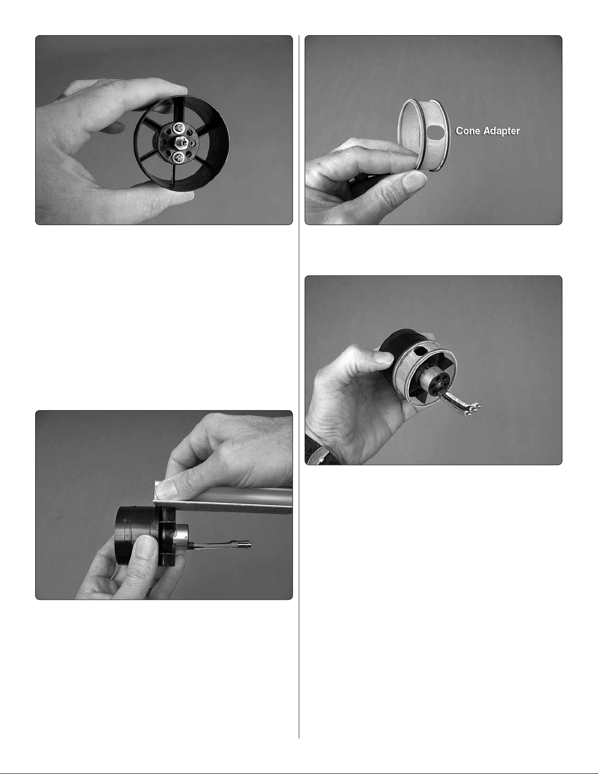
11. Mount the motor to the fan housing with two of the 3
❏
x 5mm screws packaged with the Ammo motor; one or two
washers for each screw; and a drop of threadlocker on the
threads. The washers will make sure the screws don’t bottom
out on the fi berglass insulator ring inside the motor.
12. As shown in step 6 in the HyperFlow manual, test-fi t
❏
the stator extension to the fan housing—make sure the little
notch in each stator blade allows the blade to fi t all the way to
the blades in the housing. If necessary, slightly enlarge any
notches that interfere for a proper fi t.
13. Once satisfi ed with the fi t of the stator extension, carefully
❏
glue it to the fan housing with CA—use CA sparingly so as
not to let excess run down inside the housing.
15. Use medium-grit sandpaper to smooth the rough edges
❏
around the motor wire hole in the fi berglass cone adapter so
it won’t damage the motor wires.
16. Test-fi t, but do not glue the cone adapter to the rear of
❏
the fan housing. Note that the hole in the housing should be
180 degrees from the side of the motor where the wires exit—
this will be the top of the unit. Once you have the housing and
adapter mated correctly, permanently glue the two together by
adding a few drops of thin CA to the seam around the outside.
Also apply a few drops of medium CA to each stator blade
where it contacts the inside of the adapter—again, use CA
sparingly so as not to cause excess to run down inside the fan.
14. Lightly sand the edge of each blade on the stator
❏
extension to remove any fl ashing and to make sure they are
even with the housing.
17. Fit the cone to the fan and the fan onto the adapter
❏
with all the dimples aligned. Secure the cone and fan to the
adapter with a 3mm screw and washer, but don’t use any
threadlocker yet.
7
Page 8
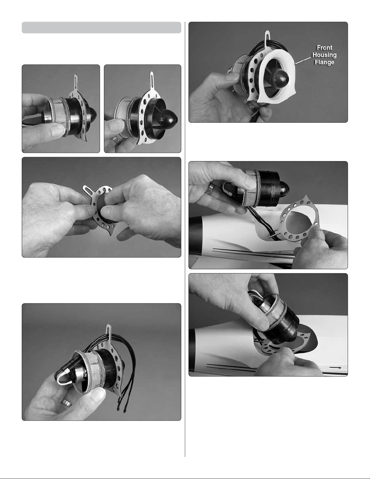
Mount the Fan in the Fuselage
Installation of the fan unit may takes a little “fi ne tuning” to
get the parts into position. Once glued in it is permanent, but
the motor and fan may still be removed if ever required later.
3. Test fi t the front housing fl ange into the fan housing
❏
just to make sure it fi ts—if necessary, trim or sand a slight
bevel inside the edge of the housing to easily accommodate
the fl ange.
1. Test fi t the plywood fan housing mount over the fan
❏
housing to make sure it fi ts—it should fi t slightly snug, but not
too tight because you’ll be installing the housing through the
mount while both parts are in the fuselage. If the mount fi ts too
tightly over the housing sand the inside of the mount so it fi ts.
2. Carefully bend the motor wires upward toward the hole in
❏
the fi berglass cone adapter, then connect the motor extension
wires through the hole. While you’re at it, position the plywood
housing mount and guide the motor wires through it.
4. Remove the fl ange and housing mount from the fan unit,
❏
but don’t take the wires out of the housing mount. With the
housing mount off the fan unit but the motor wires running
through the mount, fi t the mount and fan unit through the
cheater hole in the bottom of the fuselage. Key the fi berglass
adapter ring on the back of the fan unit around the inside of
the fi berglass tail cone in the fuselage, then fi t the plywood
housing mount over the fan housing. If you cannot get the
housing mount all the way into position do not force it. Proceed
to the next step.
8
Page 9

5. If necessary, use a pencil to mark the edges of the
❏
plywood housing mount where it requires any trimming to fi t.
Hint: You should be able to prop the fuselage vertically on
your workbench, making it easy to see. Mark any areas of the
housing mount that require trimming.
6. Take out the fan and housing mount, then trim the mount
❏
where you marked it for trimming. Continue to fi t and trim the
housing mount as necessary until you can get a good fi t.
8. Test-fi t the front housing fl ange, making sure it is keyed
❏
around the inside of the fan housing. Make any adjustments
for a good fi t.
9. Once satisfi ed with the fi t of the front housing fl ange
❏
take it out of the fuselage. Apply a bead of thick CA around
the lip where it fi ts into the housing, then reposition it into the
fuselage and housing. Immediately wipe away any excess CA.
7. Once you can get a good fi t, remove the housing mount
❏
and fan unit. Apply a fi llet of thick, slow-drying glue such as
30-minute epoxy mixed with microballoons or Zap Goo around
the end of the cone adapter ring. Install the fan unit and ply
housing mount into position, making certain the adapter ring
is keyed all the way around the inside of the tail cone. Wipe
off any excess glue, then use thick or medium CA to glue
the fan housing mount to the fuselage and the fan unit to the
fan mount.
10. After the CA has hardened, use 30-minute epoxy
❏
mixed with microballoons, Zap Goo or RTV silicone to make
a fi llet around the fl ange to the fuselage. Permanently glue
the fl ange into position.
9
Page 10

11. Bevel the edges around the balsa fi n hole cover, then
❏
fi t and glue into position.
12. Mount the bungee hook to the bottom of the fuselage
❏
with a 3mm nut, washer and threadlocker on the threads.
ASSEMBLE THE WING
2. Use a covering iron with a cover sock to go over the
❏
wings and servo hatches and remove any wrinkles. When you
do fi nd wrinkles, fi rst glide the iron over the area to shrink the
wrinkle. Allow to cool for a second or two, then go back over
the spot, pressing down to bond the covering to the wood. If
the wrinkles won’t go away and just bubble up, reduce the
heat of your iron.
1. Pull hard on both elevons to make sure the hinges and
❏
the elevons are secure. If any hinges come out or seem loose,
add a few drops of thin CA to the hinge in the gap, allow to
harden, and then test again.
3. Temporarily connect your servos, receiver, ESC and
❏
battery and power them up with your transmitter.
10
Page 11

Right Wing Servo
Right Aileron Control Input
Left Wing Servo
Right Wing Servo
“Up” Elevator Control Input
Left Wing Servo
4. Make sure all the trims and sub trims are “zeroed” in
Cut off
the unused
arms
Right Wing Servo Left Wing Servo
5°
5°
❏
your transmitter. Program the mixing in your transmitter so the
servos respond in the correct direction as illustrated.
6. Cut the 1/32" x 3/4" x 1- 9/16" [1 x 20 x 40mm] balsa
❏
sheet in half. Use medium-grit sandpaper to roughen the side
of each servo, then use medium CA to glue each balsa sheet
to the side of each servo. Caution: Do not use thin CA for
this step because it could wick into the servo through seams
in the case.
7. Use a #53 (.046" [1.2mm]) drill to enlarge the holes in
❏
your servo arms and the holes in the included control horns
to fi t the 1.2mm Z-bend pushrods. If you don’t have a drill you
can use a hobby blade, but do so carefully and don’t oversize
the holes or there will be free play in the linkages.
5. Mount the servo arms to your servos so the inward-
❏
opposing arms will have an approximately 5-degree angle
as shown. Cut off the unused arms.
8. Use a straightedge and a pencil to mark lines on across
❏
the inside of the hatch centered over the four screw holes. Glue
the servos to the hatches with medium CA, making sure the
servo doesn’t extend over any of the lines.
11
Page 12

9. Enlarge the four hatch mounting holes in each wing with
1/4"
[6−7 mm]
Outer Hole
❏
a 1/16" [1.6mm] drill.
12. Temporarily mate one of the short Z-bend pushrods
❏
to the long pushrod on the servo with two collars and set
screws, then fi t one of the aileron horns onto the pushrod
through the outer hole.
13. Cut an Aileron Horn Template from the back of the
❏
manual and align it with the trailing edge of the wing as shown.
Position the template so the pushrod will be directly behind
the servo arm and perpendicular to it.
10. Temporarily mount the hatches in the wings with the
❏
washer-head Phillips screws. Take out the screws, add a drop
or two of thin CA in each hole and allow to harden.
From here you can do one wing at a time, or work on them
both simultaneously.
11. Insert one of the long
❏
Z-bend pushrods through the
hole in the servo arm that
is closest to 1/4" [6 –7 mm]
out, then mount the arm to
the servo with the servo arm
screw and mount the hatch
to the wing.
14. Drill 3/32" [2.4mm] holes holes through the aileron
❏
where marked on the template (or use a 3/32" brass tube
sharpened on the end to cut perfectly clean holes).
12
Page 13

Mount the Wing Skids
1. The wing skids come pretty much ready to glue on, but
❏
if you want perfection you could true the factory-cut edges
a little with a bar-sander and 80-grit sandpaper followed by
320-grit fi nishing with 400-grit to smooth the edges.
2. Determine which skid is the right and which is the left
❏
by test-fi tting them onto the wing and seeing how they fi t best.
Let’s do the right one fi rst…
15. Loosen the collars to adjust the length of the pushrod
❏
assembly as necessary, then mount the horn to the aileron
with the retainer on the top. (Hint: Use a 1/8" brass tube
to tightly push the retainer over the posts on the top of the
aileron.) Use a small pin to poke holes around the base of
the retainer and the horn. Then apply thin CA to securely glue
the horn into place.
3. Position the right skid on the bottom of the right wing
❏
with the aft edge of the skid approximately 1/16" [1.5mm]
ahead of the wing trailing edge and the inner edge of the
skid approximately 1/16" [1.5mm] away from the edge of the
hatch. Holding the skid in position, use a fi ne-point felt-tip pen
to mark the outline of the skid onto the wing.
4. Use a small pin to poke pin holes through the covering
❏
all the way the inside edge of the line.
16. If you haven’t yet done so, hook up the other elevon
❏
the same way. Final elevon setup will be done later after the
wings have been attached to the fuselage, so don’t worry about
adjusting the pushrods and tightening the collars at this time.
13
Page 14

5. Use a piece of paper towel dampened with denatured
5-1/16" [129 mm] 5-1/16" [129 mm]
❏
alcohol to wipe off the ink lines. Position the skid aligned over
the pin holes so none of them are visible. Then permanently
glue the skid to the wing with thin CA.
6. Fit, then glue on the other wing skid the same way.
❏
Finish the Wings
is recommended with 10" [255mm] being the minimum, so
use whatever length extensions you need. For each Futaba
S3157 servo, a Futaba 75mm J-Series extension was used
(FUTM3909). Use tape or heat-shrink tubing to secure the
connection between the extension and the servo wire.
1. Fit, then use thin CA to glue the alignment pegs into
❏
the root of both wings near the leading and trailing edge.
2. Connect a servo wire extension to each aileron servo wire
❏
coming out of the wing—just enough wire is needed so you
can reach the plugs through the canopy hatch for plugging into
your receiver—a total of 10" to 12" [255mm—300mm] of wire
3. Accurately measure and mark the starting, recommended
❏
C.G. location on the root rib of both wings 5-1/16" [129mm]
back from the leading edge of each panel. Temporarily fi t
the wings together with the aluminum joiner tube, then use
a felt-tip pen and a straightedge to extend the lines partway
across the top of the wing as shown. (Don’t worry, the ink will
be wiped away later.)
14
Page 15

Mount the Wings to the Fuselage
1. Test-fi t one, then the other wing to the fuselage with the
❏
aluminum wing joiner tube. Make any adjustments necessary
for a good fi t.
It is desirable not to have the wings permanently glued to
the fuselage. If replacement or major repair is ever required,
having the wings easily removable will be a relief if the time ever
comes. RTV silicone is defi nitely suitable, but even though it
can be relatively easily cut through, it is diffi cult to remove from
the fi berglass fuselage. Zap Goo is another option because it
bonds well, yet can be peeled off when required.
FINAL ASSEMBLY
1. Connect the three motor wires to the ESC and temporarily
❏
power the system up just enough to see if the motor is turning
in the correct direction. If the motor is not turning the correct
direction switch any two of the motor wires with each other.
2. Attach the wings to the fuselage using whatever adhesive
❏
you prefer. Use masking tape to tightly hold the wings to the
fuselage while the glue dries.
3. While the fuselage is upside-down, center the nose skid
❏
on the bottom of the fuselage and glue it into position with
thin CA. The precise location isn’t critical, but try to get the
skid centered.
2. Disconnect the battery from the ESC. Determine where
❏
you will mount the ESC and receiver—the ESC can be mounted
just aft of the opening in one of the intake ducts and the
receiver can be attached to the bottom of the fuselage aft of
the battery platform. Use a piece of paper towel dampened
with denatured alcohol to clean the areas where you will
mount the ESC and receiver, then mount each one with the
included double-sided foam mounting tape.
15
Page 16

3. Use tape or the included plastic tube to position and mount
❏
the receiver antenna(s) inside the fuselage as recommended
by the manufacturer. For the Futaba R617FS one of the
antennas was guided forward under the battery fl oor and the
other was taped to the inside of the fuselage running up the
side and over the top.
4. Cut the rest of the way through the holes in the battery
❏
fl oor and remove the plywood pieces.
5. Connect the Velcro battery straps to each other and glue
❏
them to the bottom of the plywood battery mount plate. Also
apply the adhesive-back Velcro strips to the top of the battery
mount plate and the bottom of your battery—the rougher,
“hook” side goes on the mount plate and the softer, “loop” side
goes on the battery.
6. Mount the battery to the mount plate and strap it down
❏
with the strap.
7. Mount the battery and mount plate in the fuselage with
❏
the 3 x 10mm screw and washer. When mounting the battery
“for real” later when you are ready to fl y, you will be reminded
to add a few drops of threadlocker to the threads of the screw.
Apply the Decals
1. Apply the optional fi nger grips to both sides of the
❏
fuselage if desired. They aren’t necessary, but may help
modelers who have problems with gripping the fuselage.
2. Use scissors or a sharp hobby knife to cut the decals
❏
from the sheet.
16
Page 17

3. Be certain the model is clean and free from oily fi ngerprints
❏
and dust. Prepare a dishpan or small bucket with a mixture
of liquid dish soap and warm water—about one teaspoon of
soap per gallon of water. Submerse the decal in the soap and
water and peel off the paper backing. Note: Even though the
decals have a “sticky-back” and are not the water transfer type,
submersing them in soap & water allows accurate positioning
and reduces air bubbles underneath.
4. Position decals on the model where desired. Holding the
❏
decal down, use a paper towel to wipe most of the water away.
5. Use a piece of soft balsa or something similar to squeegee
❏
remaining water from under the decal. Apply the rest of the
decals the same way.
GET THE MODEL READY TO FLY
IMPORTANT INFORMATION: The Phazer is slightly
more sensitive to the C.G. location than other models, so be
certain to check and set the C.G. according to the instructions
in this manual. More than any other factor, the C.G. (center
of gravity/balance point) can have the greatest effect on
how a model fl ies and could determine whether or not your
fi rst fl ight will be successful. If you value your Phazer and
wish to enjoy it for many fl ights, DO NOT OVERLOOK THIS
IMPORTANT PROCEDURE. A model that is not properly
balanced may be unstable and possibly unfl yable.
2. Use regular tape or double-sided tape to securely, but
❏
temporarily hold the plywood C.G. supports to the wing
approximately 1/16" [1.5mm] from the fuselage.
1. Assemble and glue together the included balance stand
❏
and balance gauge.
3. With the Phazer in ready-to-fl y condition and the battery
❏
and all other components installed, key the pointed ends of
the posts on the balance stand into the middle holes in the
supports on the wing, then fl ip the assembly over placing the
stand on its base to see where the model balances.
This is where the Phazer should balance for the fi rst fl ights.
Later, you may experiment by shifting the C.G. 5/16"
[8mm] forward or 5/16" [8mm] back to change the fl ying
characteristics. Moving the C.G. forward will improve stability,
but will also decrease maneuverability. Moving the C.G. aft
will allow the Phazer to fl y slower, but it will then be less
stable and bleed off even more speed in turns. In any case,
start at the recommended balance point and do not at
any time balance the model outside the specifi ed range.
17
Page 18

4. See where the Phazer balances supported at the middle
FULL
THROTTLE
BOTH ELEVONS MOVE UP
RIGHT ELEVON MOVES UP
LEFT ELEVON MOVES DOWN
4-CHANNEL
RADIO SET UP
(STANDARD MODE 2)
❏
holes in the support guides. Shift the battery forward or back
as necessary and/or temporarily lay segments of lead ballast
over the nose to get it to balance. Our prototypes required
approximately .5 oz. in the nose to balance at the recommended
location, or no ballast to balance slightly aft.
5. Once you fi nd out how much (if any) ballast is required
❏
and/or where to position the battery on the mount plate, install
the weight inside the fuselage.
1. Turn on the transmitter and connect the motor battery.
❏
Double-check that the elevons respond in the correct direction
according to your transmitter stick movments. Adjust the
programming as necessary.
6. Double-check the C.G. with the gauge. Make any
❏
adjustments necessary by shifting the battery, then mark the
fi nal location of the battery onto the battery plate so you will
always know where to position it.
To ensure a successful fi rst fl ight it is important that the
Phazer is set up according to the control throws specifi ed
in this manual. The throws have been determined through
actual fl ight testing and accurate record-keeping allowing the
model to perform in the manner in which it was intended. If,
after you have become accustomed to the way the Phazer
fl ies, you would like to change the throws to suit your taste,
that is fi ne. However, too much control throw could make the
model too responsive and diffi cult to control, so remember,
“more is not always better.”
Set the Control Throws
2. With the trims and sub trims in your transmitter centered,
❏
loosen the collars and adjust the pushrods so the elevons will
have 1/32" to 1/16" [.8mm – 1.6mm] up trim relative to the
wing tip. This is the normally-trimmed condition which allows
the Phazer to fl y level.
3. One-at-a-time, remove the set screws in the collars,
❏
lightly wet the threads with threadlocker, then securely tighten
the screws.
18
Page 19

These are the recommended control surface throws:
ELEVATOR
LOW RATE
AILERONS
HIGH RATE
3/16"
[5mm]
9°
Up
1/8"
[3mm]
6°
Up
3/8"
[10mm]
17°
Up
3/16"
[5mm]
9°
Up
3/16"
[5mm]
9°
Down
1/8"
[3mm]
6°
Down
3/8"
[10mm]
17°
Down
3/16"
[5mm]
9°
Down
PREFLIGHT
Run-In the Fan
If possible perform this procedure outdoors. In any case, wear
eye and hearing protection and request that any observers
leave the room.
Follow the preparation and break-in procedures on the back
page of the HyperFlow instruction manual for running-in your
fan. Sometimes these HyperFlow fan units can emit a little
resonance while transitioning through the rpm range, which is
OK, but it must run smoothly at full-throttle. If the fan doesn’t
run smooth at full-throttle or if the resonance is more than you
are willing to tolerate, follow the procedure to balance the fan:
4. Now set the elevator and aileron throws according to the
❏
measurements below: (Hint: If necessary, use a scrap sheet
of balsa or cardstock to shim up your ruler, making it easier
to read the measurements.)
If your radio does not have dual rates, we recommend setting
the throws at the high rate settings.
NOTE: The throws are measured at the widest part of the
elevons (at the root end next to the fuselage).
IMPORTANT!: When giving an elevator command from
the control stick it is imperative that the defl ection of both
elevons is precisely identical to each other. Otherwise, the
Phazer may yaw toward or away from the ground in banked
turns, not to mention rolling out of loops. Spend time and
use your critical eye to make sure both elevons defl ect the
same when an elevator input is given.
1. Disconnect the battery from the ESC. Insert a #2 Phillips
❏
screwdriver into the cheater hole opening and into the fan cone.
Hold the fan with one fi nger while turning the screwdriver to
loosen the screw just enough to rotate the cone.
2. Using the dimple you made on the fan cone as an
❏
alignment cue, rotate the cone so the dimple aligns with the
next fan blade over. Tighten the Phillips screw, connect the
battery, then run up the fan again to see if it smooths out.
Continue the procedure, rotating the cone one blade at a time
until you can get it to run smoothly. If you cannot get the fan
to run smoothly, proceed to the next step.
19
Page 20

ROTOR PULLER
1" [25mm]
3-1/2" [90mm]
1/4" [6mm]
3. If you cannot get the fan unit to run smoothly by rotating
❏
the cone, perform the same procedure with the fan—use the
dimple you marked on the brass rotor adapter to rotate and
realign the fan “one hex at a time” until the unit runs smoothly.
You should be able to pull the fan with your fi ngers, but if
necessary you can make this “fan puller” from a piece of 1/16"
[1.6mm] pushrod wire or music wire. You should be able to
fi nd an alignment combination of the fan and cone to get the
unit to run smoothly.
4. When fi nished, be certain to securely tighten the Phillips
❏
screw with a drop of threadlocker.
Identify Your Model
No matter if you fl y at an AMA sanctioned R/C club site or if
you fl y somewhere on your own, you should always have your
name, address, telephone number and AMA number on or
inside your model. It is required at all AMA R/C club fl ying sites
and AMA sanctioned fl ying events. Fill out the identifi cation
tag on the decal sheet and place it on or inside your model.
Assemble the Bungee Launch
1. Loop one end of the rubber tubing and insert it through
❏
one of the metal rings.
2. Bend the loop down around the ring. Then pull the ring
❏
the rest of the way through the loop.
Charge the Batteries
Follow the battery charging instructions that came with your
radio control system to charge the batteries. You should always
charge your transmitter and receiver batteries the night before
you go fl ying, and at other times as recommended by the
radio manufacturer.
CAUTION: Unless the instructions that came with your
radio system state differently, the initial charge on new
transmitter and receiver batteries should be done for 15
hours using the slow-charger that came with the radio
system. This will “condition” the batteries so that the next
charge may be done using the fast-charger of your choice.
If the initial charge is done with a fast-charger the batteries
may not reach their full capacity and you may be fl ying with
batteries that are only partially charged.
3. Pull the tubing to tighten the knot and make sure it is
❏
secure.
Now attach the cord…
4. Loop one end of the cord through the ring.
❏
20
Page 21

5. Bring the loop in back over itself and the ring. You’ll have
❏
to pull the rest of the cord up all the way through the loop
before tightening it around the ring.
8. Attach the other end of the tubing to the stake and the
❏
other end of the cord to the other ring. Add another nylon tie
to the end of the tubing at the stake as well.
9. Now the bungee is ready to use. Wind it back up onto
❏
the plywood holder.
AMA SAFETY CODE
Read and abide by the following excerpts from the Academy
of Model Aeronautics Safety Code. For the complete Safety
Code refer to Model Aviation magazine, the AMA web site or
the Code that came with your AMA license.
General
1) I will not fl y my model aircraft in sanctioned events, air shows,
or model fl ying demonstrations until it has been proven to be
airworthy by having been previously, successfully fl ight tested.
2) I will not fl y my model aircraft higher than approximately
400 feet within 3 miles of an airport without notifying the
airport operator. I will give right-of-way and avoid fl ying in the
proximity of full-scale aircraft. Where necessary, an observer
shall be utilized to supervise fl ying to avoid having models fl y
in the proximity of full-scale aircraft.
6. Pull tightly on the tubing and the cord to make sure it is
❏
secure. Add a drop of thin or medium CA to the knot in the
cord over the ring.
3) Where established, I will abide by the safety rules for the
fl ying site I use, and I will not willfully and deliberately fl y my
models in a careless, reckless and/or dangerous manner.
5) I will not fl y my model unless it is identifi ed with my name
and address or AMA number, on or in the model. Note: This
does not apply to models while being fl own indoors.
7) I will not operate models with pyrotechnics (any device that
explodes, burns, or propels a projectile of any kind).
Radio Control
1) I will have completed a successful radio equipment ground
check before the fi rst fl ight of a new or repaired model.
2) I will not fl y my model aircraft in the presence of spectators
until I become a qualified flier, unless assisted by an
experienced helper.
3) At all fl ying sites a straight or curved line(s) must be
established in front of which all fl ying takes place with the
other side for spectators. Only personnel involved with fl ying
the aircraft are allowed at or in the front of the fl ight line.
Intentional fl ying behind the fl ight line is prohibited.
7. Secure the end of the tubing to the ring with one of the
❏
included small nylon ties.
4) I will operate my model using only radio control frequencies
currently allowed by the Federal Communications Commission.
5) I will not knowingly operate my model within three miles
of any pre-existing fl ying site except in accordance with
the frequency sharing agreement listed [in the complete
AMA Safety Code].
21
Page 22

9) Under no circumstances may a pilot or other person touch
a powered model in fl ight; nor should any part of the model
other than the landing gear, intentionally touch the ground,
except while landing.
CHECK LIST
During the last few moments of preparation your mind may
be elsewhere anticipating the excitement of the fi rst fl ight,
causing you to overlook certain checks and procedures.
Follow the check below to avoid this.
Here’s how to calculate your own fl ight times:
You need to know three things:
A. The target capacity you want to use from your battery
for a fl ight.
B. How long you fl ew.
C. How much capacity was used from the battery for that
fl ight.
To prevent over discharging your battery you should use
no more than 80% of your battery’s capacity. If using the
recommended 2200mAh battery that would be 1760mAh
(2200mAh x .8).
1. Confi rm that all controls operate in the correct direction.
❏
2. Make certain you’ve set the C.G. and the control throws
❏
according to the measurements provided in the manual.
3. Make sure the servo arms are secured with the screws
❏
that came with them and make sure the set screws in the
collars on the pushrods are tightened with threadlocker.
4. Make sure the elevon horns are secure and glued.
❏
5. Make sure the receiver antenna(s) are mounted per the
❏
manufacturer’s instructions.
6. Tug on the elevons to make sure all the hinges are
❏
securely glued in place.
7. Place your name, address, AMA number and telephone
❏
number on or inside your model.
8. Range check your radio when you get to the fl ying fi eld.
❏
FLYING
The Phazer is a great-fl ying model that fl ies smoothly and
predictably, but it possesses no self-correcting tendencies
what-so-ever and therefore, must be fl own only by reasonably-
experienced pilots who are able to decisively provide the
correct control inputs.
Ground Check and Range Check
Say for example, you fl ew for three minutes and it took 1275mAh
to recharge your battery. Since your limit is 1760mAh you still
had 485mAh to go, so lengthen your fl ight time accordingly. You
could also calculate that the consumption rate for that fl ight
was 425mAh per minute (1275mAh divided by 3 minutes).
Dividing your target capacity of 1760mAh/minute by 425mAh/
minute gives you a fl ight time of 4.1 minutes (4 min. 6 seconds—
virtually 4 minutes.)
Do this for several trials (or for every fl ight!) to calculate
accurate values for how long you can fl y!
Launching
Don't forget to install the 3mm battery plate screw with
threadlocker. This needs to be done only once every dozen
or so fl ights as residual threadlocker suffi ciently holds the
screw in place.
The Phazer may be hand-launched or bungee-launched by
an assistant or by the pilot. If you’re at all hesitant, the easiest
and surest way to get your Phazer airborne is to have an
assistant bungee launch it for you—at least for the maiden
fl ight. After that you can bungee-launch it yourself every time.
Experienced pilots who don’t feel like setting up the bungee
can defi nitely hand-launch the Phazer themselves, or have
an assistant hand-launch it for them. The bungee might be a
bit of a hassle to unwind, lay out and put away, but it’s a no-
brainer and guaranteed to get your Phazer in the air.
Perform an operational ground check of your radio following
the manufacturer’s instructions that came with your radio.
Set a Flight Timer
Prevent over discharging your LiPos and/or dead-stick landings
by using the timer in your transmitter (or a separate timer if
your transmitter doesn’t have one) to signal when it’s time to
land. If your transmitter has a timer built in, link the timer to
the throttle stick so it starts and stops when the stick is raised
to about 10% – that way you’ll be counting actual motor run
time, not total air time.
Until you have the data to make your own calculations, set
your timer to a conservative 3-minutes so you won’t go over.
To bungee-launch the Phazer, be sure the ground will hold the
stake securely, then push it all the way in at about a 45 degree
angle away from the launch spot. Unwind the bungee, laying it
out so the launch will be into the wind. As the bungee unwinds,
always inspect the tubing and cord to make sure there are no
cuts, cracks, tears or any other defects. Also make sure the
line and cord are securely connected to the rings and stake.
After you have the bungee laid out, but before stretching it
out, turn on your transmitter and connect the battery. As you
should always do before every fl ight, double-check that
the controls are responding properly and in the correct
direction, then arm the motor and run it up for a second to
make sure it is making full power.
22
Page 23

Stretch out the bungee, walking fi fteen to twenty steps away downward, from the stake. Then connect it to the hook on the
Throw the Phazor underhanded
− focus on keeping the wings level.
bottom of the plane. If using an assistant, inform him of your intentions and make sure he acknowledges, then go to full
throttle. Holding the Phazer at an approximately 30 degree angle, wings level, give it a good push into the air and let go.
The Phazer should lunge forward. Then it may descend slightly before it gets up to fl ying speed—this will all happen in about
a second, so you need to get your fi ngers back on the sticks right away! Fly the Phazer out of the launch and the bungee
will automatically release.
After you get a few bungee launches under your belt the only hard part will be remembering to wind it back up and bring it
back home with you!
With hand-launching, the main hurdle to overcome will be fl ying speed—the bungee gets the Phazer up to speed right away,
but the Phazer has to fl y away from a hand-launch and build speed on its own.
Whether the pilot or an assistant, hold the Phazer over the top of the fuselage so it can be thrown in an underhand fashion.
Though it is important to throw the Phazer hard, concentrate more on throwing it with the wings level and the nose pointed
up at about a 20 – 30-degree angle. When ready, go to full-throttle, then throw the Phazer into the air. Remember to focus on
keeping the wings level. Initially, the Phazer will have little fl ying speed, so the pilot won’t have much control (emphasizing the
importance of a good launch). The Phazer will gradually build up enough speed and fl y away, but as long as the wings are
level the worst thing that will happen is it will simply land! If the launch was poor and the wings are not level you have to hope
it can gain enough airspeed to fl y out of it. Otherwise your Phazer may go in with the wings banked, possibly causing damage.
Factors that help the hand-launch are launching on high rates, having the C.G. anywhere between the recommended location
and the aft location, and launching into a headwind. Same as with the bungee-launch, it’s best to have an assistant handlaunch the Phazer the fi rst time so you will know what to expect when you’re ready to try it yourself.
Bungee launches are consistent because most of the human factor has been taken out. But human error can cause the
hand-launch to go wrong, so make sure you (or your assistant) know what they’re doing before trying a hand-launch.
With a good launch the Phazer will eventually gain speed and easily fl y away. Then you’ll wonder what all the fuss was about!
23
Page 24

Flying
Simply stated, the Phazer is a “hoot” to fl y! It sounds pretty
cool, looks quirky and cute in the air and is actually quite docile
even though it’s pretty fast. But delta-wing airframes do have
a few peculiarities that you should anticipate. The Phazer is
unusually stable and will not stall and spin from turning too
sharply, but it does bleed off speed in tight turns—if you turn
too tightly for too long it will bleed off enough airspeed to lose
signifi cant altitude or the nose may rotate downward, so just
fl y it “large” for the fi rst minute until you get used to it. And
same as any jet, more time and distance are required to get
the Phazer back up to speed after throttling up, so you have
to fl y “ahead” of it some.
Those two concepts in mind, once airborne the primary
objective will be to get the Phazer trimmed for straight-andlevel fl ight. It’s not so fast that you won’t be able to fl y it full
throttle, but fl y it around at whatever speed you are comfortable
with while you are getting it trimmed. Also test how the Phazer
responds on high and low rates (but you’ll probably end up
fl ying it on high rates most of the time). Try some rolls, loops
and inverted fl ight. If you fi nd the nose of the Phazer yawing
downward in turns, the C.G. may be too far forward. Try moving
the C.G. aft.
your approaches a little shorter, or simply “drag” it in with some
throttle. If you end up coming in hot simply throttle up, fl y by
and go around again. When the Phazer does touch down it
safely glides along the grass before coming to a quick stop.
After every landing inspect the intake, fan and exhaust tube
and remove any grass or debris—and don’t forget to note
how long you fl ew on that battery so you can start calculating
your own fl ight times!
One fi nal note about fl ying your Phazer. Have a goal or fl ight
plan in mind for every fl ight. This can be learning a new
maneuver(s), improving a maneuver(s) you already know,
or learning how the model behaves in certain conditions
(such as on high or low rates). This is not necessarily to
improve your skills (though it is never a bad idea!), but more
importantly so you do not surprise yourself by impulsively
attempting a maneuver and suddenly fi nding that you’ve run
out of time, altitude or airspeed. Every maneuver should be
deliberate, not impulsive. For example, if you’re going to do a
loop, check your altitude, mind the wind direction (anticipating
rudder corrections that will be required to maintain heading),
remember to throttle back at the top, and make certain you
are on the desired rates (high/low rates). A fl ight plan greatly
reduces the chances of crashing your model just because
of poor planning and impulsive moves. Remember to think.
Landing
While at altitude and still with plenty of battery power, simulate
a few landing approaches by cutting the throttle and watching
how the Phazer glides. Then throttle up, go around and try
it again. You might notice that the Phazer bleeds off speed
a little faster than you expected. Knowing this you can make
Have a ball! But always stay in control
and fl y in a safe manner.
GOOD LUCK AND GREAT FLYING!
Name
Address
City, State, Zip
This model belongs to:
AMA Number
Phone Number
Aileron Horn Template
24
 Loading...