

Great Planes GPMA1801 User Manual
®
®
INSTRUCTION MANUAL
SPECIFICATIONS
Wingspan: 22.5 in [570 mm]
2
Wing Area: 166 in
Wing Loading: 27.8−29.5 oz/ft
[10.7 dm2]
2
[85−90 g/dm2]
Length: 34.5 in [875mm]
WARRANTY
Great Planes Model Manufacturing® Co. guarantees this kit to
be free from defects in both material and workmanship at the
date of purchase. This warranty does not cover any component
parts damaged by use or modification. In no case shall Great
Planes’ liability exceed the original cost of the purchased kit.
Further, Great Planes reserves the right to change or modify this
warranty without notice.
In that Great Planes has no control over the final assembly or
material used for final assembly, no liability shall be assumed nor
accepted for any damage resulting from the use by the user of
the final user-assembled product. By the act of using the
user-assembled product, the user accepts all resulting liability.
If the buyer is not prepared to accept the liability associated
with the use of this product, the buyer is advised to return
Weight Range: 32−34 oz
Radio: 4-channel,
™
,
[910−960 g]
Motor, ESC: 24-45-3790kV Ammo
35A ESC,
HyperFlow
™
56mm fan
4 micro servos,
mini receiver
this kit immediately in new and unused condition to the
place of purchase.
To make a warranty claim send the defective part or item to
Hobby Services at the address below:
Hobby Services
3002 N. Apollo Dr. Suite 1
Champaign IL 61822 USA
Include a letter stating your name, return shipping address, as
much contact information as possible (daytime telephone
number, fax number, e-mail address), a detailed description of
the problem and a photocopy of the purchase receipt. Upon
receipt of the package the problem will be evaluated as quickly
as possible.
READ THROUGH THIS MANUAL BEFORE STARTING CONSTRUCTION. IT CONTAINS IMPORTANT
INSTRUCTIONS AND WARNINGS CONCERNING THE ASSEMBLY AND USE OF THIS MODEL.
Entire Contents © 2011 Hobbico,® Inc. All rights reserved.
Champaign, Illinois
(217) 398-8970, Ext 5
airsupport@greatplanes.com
GPMA1801 Mnl
TABLE OF CO NTENTS
INTRODUCTION . . . . . . . . . . . . . . . . . . . . . . . . . . . . . . . . 2
Academy of Model Aeronautics . . . . . . . . . . . . . . . . . . 2
SAFETY PRECAUTIONS . . . . . . . . . . . . . . . . . . . . . . . . . 2
DECISIONS YOU MUST MAKE . . . . . . . . . . . . . . . . . . . . 3
Battery and ESC . . . . . . . . . . . . . . . . . . . . . . . . . . . . . 3
Servos, Receiver . . . . . . . . . . . . . . . . . . . . . . . . . . . . . 3
ADDITIONAL ITEMS REQUIRED. . . . . . . . . . . . . . . . . . . 4
Battery Chargers . . . . . . . . . . . . . . . . . . . . . . . . . . . . . 4
Adhesives and Building Supplies. . . . . . . . . . . . . . . . . 4
Optional Supplies and Tools . . . . . . . . . . . . . . . . . . . . 4
KIT INSPECTION . . . . . . . . . . . . . . . . . . . . . . . . . . . . . . . 4
ORDERING REPLACEMENT PARTS . . . . . . . . . . . . . . . 4
KIT CONTENTS. . . . . . . . . . . . . . . . . . . . . . . . . . . . . . . . . 5
ASSEMBLY INSTRUCTIONS . . . . . . . . . . . . . . . . . . . . . . 6
Assemble the Stand. . . . . . . . . . . . . . . . . . . . . . . . . . . 6
Prepare the HyperFlow Fan Unit . . . . . . . . . . . . . . . . . 6
Test Run the Motor/Fan Unit . . . . . . . . . . . . . . . . . . . . 8
Surface Preparation . . . . . . . . . . . . . . . . . . . . . . . . . . . 8
Install the Fan Unit . . . . . . . . . . . . . . . . . . . . . . . . . . . . 8
Assemble the Wing . . . . . . . . . . . . . . . . . . . . . . . . . . 10
Install the Wing Panels . . . . . . . . . . . . . . . . . . . . . . . 12
Install the Tail Section and Servos. . . . . . . . . . . . . . . 14
Finish the Model . . . . . . . . . . . . . . . . . . . . . . . . . . . . 17
Apply the Decals . . . . . . . . . . . . . . . . . . . . . . . . . . . . 18
GET THE MODEL READY TO FLY. . . . . . . . . . . . . . . . . 19
Set the Control Throws . . . . . . . . . . . . . . . . . . . . . . . 19
Balance the Model (C.G.) . . . . . . . . . . . . . . . . . . . . . 19
Balance the Model Laterally . . . . . . . . . . . . . . . . . . . 20
PREFLIGHT. . . . . . . . . . . . . . . . . . . . . . . . . . . . . . . . . . . 20
Identify Your Model . . . . . . . . . . . . . . . . . . . . . . . . . . 20
Charge the Batteries . . . . . . . . . . . . . . . . . . . . . . . . . 20
Assemble the Bungee Launch. . . . . . . . . . . . . . . . . . 20
AMA SAFETY CODE (excerpts) . . . . . . . . . . . . . . . . . . 21
General . . . . . . . . . . . . . . . . . . . . . . . . . . . . . . . . . . . 21
Radio Control . . . . . . . . . . . . . . . . . . . . . . . . . . . . . . . 21
CHECK LIST . . . . . . . . . . . . . . . . . . . . . . . . . . . . . . . . . . 21
FLYING . . . . . . . . . . . . . . . . . . . . . . . . . . . . . . . . . . . . . . 22
Ground Check and Range Check . . . . . . . . . . . . . . . 22
Takeoff . . . . . . . . . . . . . . . . . . . . . . . . . . . . . . . . . . . . 22
Hand-Launch . . . . . . . . . . . . . . . . . . . . . . . . . . . . . . . 22
Bungee-Launch . . . . . . . . . . . . . . . . . . . . . . . . . . . . . 23
Flying . . . . . . . . . . . . . . . . . . . . . . . . . . . . . . . . . . . . . 24
Landing . . . . . . . . . . . . . . . . . . . . . . . . . . . . . . . . . . . 24
INTRODUCTION
Thank you for purchasing the Great Planes F-16 EDF (electric
ducted fan) ARF. With average speeds approaching 100mph,
your jet will have onlookers’ full attention as it cuts across
the horizon like a full-scale F-16 on patrol. Execute a Split-S
to come in for a low, high-speed pass across the fl ight line.
The EDF’s whine at full-throttle will echo off nearby buildings,
reminding you to keep your fi ngers tight on the sticks — this
bird is moving fast! Fortunately, the F-16 is a very stable fl ier
and doesn’t require expert fl ying skills to pilot, but it’s not a
beginner’s jet. The recommended battery provides just the
right amount of fl ight time for a plane of this size and speed…
and when you do bring it in for a landing, it will slow nicely
on approach and simply “settle in” on the grass when it’s
done fl ying.
For the latest technical updates or manual corrections to the
F-16 visit the Great Planes web site at www.greatplanes.com.
Open the “Airplanes” link, then select F-16 ARF. If there is new
technical information or changes to this model a “tech notice”
box will appear in the upper left corner of the page.
Academy of Model Aeronautics
If you are not already a member of the AMA, please join! The
AMA is the governing body of model aviation and membership
provides liability insurance coverage, protects modelers’ rights
and interests and is required to fl y at most R/C sites.
Academy of Model Aeronautics
5151 East Memorial Drive
Muncie, IN 47302-9252
Tele. (800) 435-9262
Fax (765) 741-0057
Or via the Internet at: http://www.modelaircraft.org
IMPORTANT!!! Two of the most important things you can
do to preserve the radio controlled aircraft hobby are to avoid
fl ying near full-scale aircraft and avoid fl ying near or over
groups of people.
SAFETY PRE CAUTION S
Protect Your Model, Yourself & Others…
Follow These Important Safety Precautions
1. Your F-16 should not be considered a toy, but rather a
sophisticated, working model that functions very much like a
full-size airplane. Because of its performance capabilities, the
F-16, if not assembled and operated correctly, could possibly
cause injury to yourself or spectators and damage to property.
2
2. You must assemble the model according to the instructions.
Do not alter or modify the model, as doing so may result in an
unsafe or unfl yable model. In a few cases the instructions may
differ slightly from the photos. In those instances the written
instructions should be considered as correct.
3. You must take time to build straight, true and strong.
4. You must use an R/C radio system that is in good condition,
a correctly sized engine, and other components as specifi ed
in this instruction manual. All components must be correctly
installed so that the model operates correctly on the ground
and in the air. You must check the operation of the model and
all components before every fl ight.
5. If you are not an experienced pilot or have not fl own this type
of model before, we recommend that you get the assistance
of an experienced pilot in your R/C club for your fi rst fl ights.
If you’re not a member of a club, your local hobby shop has
information about clubs in your area whose membership
includes experienced pilots.
6. While this kit has been fl ight tested to exceed normal use,
if the plane will be used for extremely high stress fl ying, such
as racing, or if an engine larger than one in the recommended
range is used, the modeler is responsible for taking steps to
reinforce the high stress points and/or substituting hardware
more suitable for the increased stress.
7. WARNING: The fuselage and tail cone adapter included in
this kit are made of fi berglass, the fi bers of which may cause
eye, skin and respiratory tract irritation. Never blow into a
part to remove fi berglass dust, as the dust will blow back into
your eyes. Always wear safety goggles, a particle mask and
rubber gloves when grinding, drilling and sanding fi berglass
parts. Vacuum the parts and the work area thoroughly after
working with fi berglass parts.
and the
❍ Great Planes ElectriFly 24-45-3790kV Ammo inrunner
brushless motor (GPMG5185).
These components drop right in with no modifi cation.
The recommended battery is the:
❍ Great Planes ElectriFly 14.8V (4S) 2200mAh 25C
LiPo (GPMP0521).
Under “normal” fl ying conditions (mostly full throttle), this
provides average fl ight times of approximately 4 minutes
with approximately one more minute of motor run time for
additional landing attempts.
❍ The Great Planes ElectriFly SS-35 35 Amp brushless
ESC (GPMM1830) is also recommended.
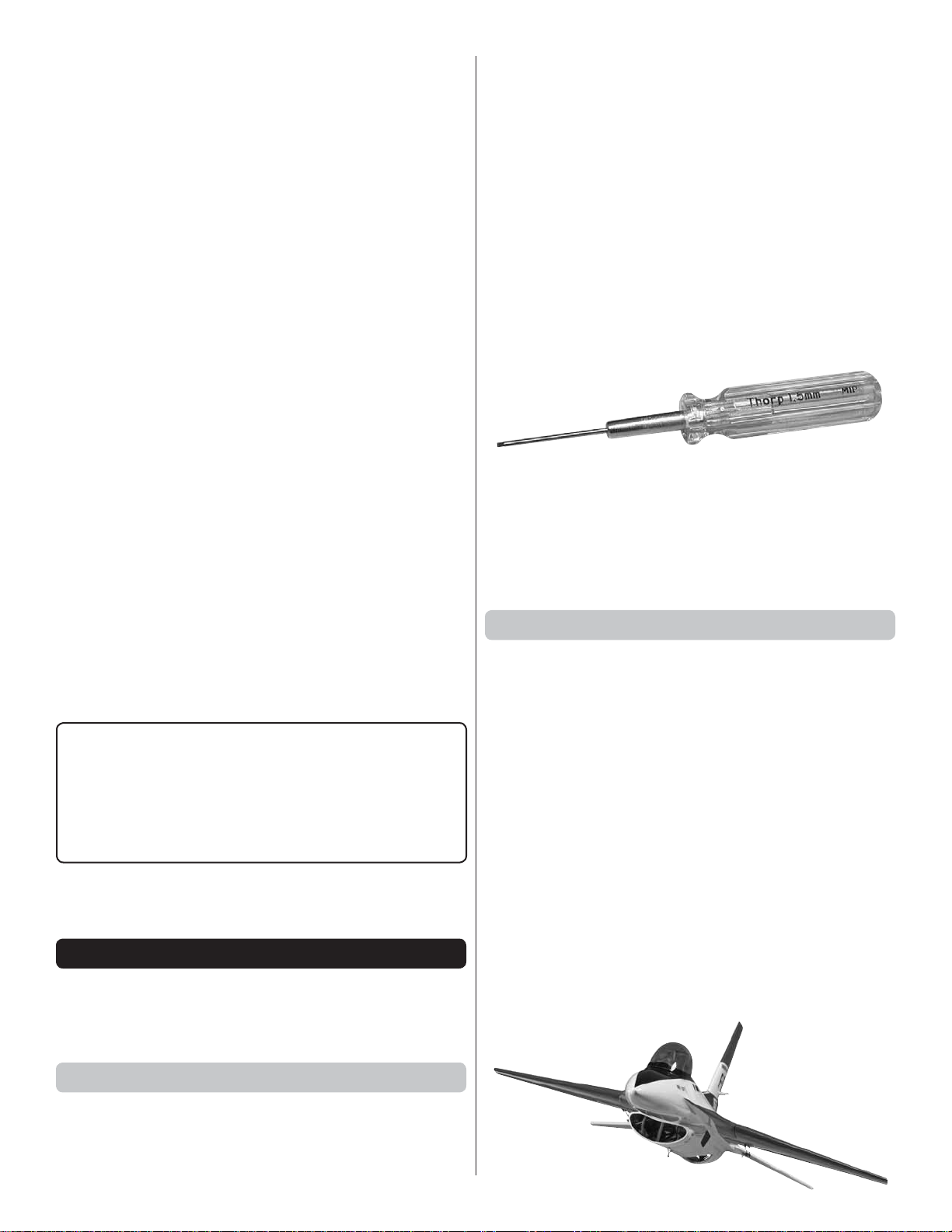
Note: A precision 1.5mm Allen wrench will be required for
tightening the set screws in the brass fan adapter. Do not
attempt to use an economy wrench. You may strip out the
wrench or set screws, making it impossible to securely tighten
or remove them for replacement. The 1.5mm MIP Thorp Hex
Driver (MIPR9007) is recommended.
Servos, Receiver
A small receiver and four micro servos in the 20 oz-in torque
range are required. Two 6" [152mm] servo extensions are also
required. Part numbers are provided below:
We, as the kit manufacturer, provide you with a top quality,
thoroughly tested kit and instructions, but ultimately the
quality and fl yability of your fi nished model depends
on how you build it; therefore, we cannot in any way
guarantee the performance of your completed model,
and no representations are expressed or implied as to the
performance or safety of your completed model.
Remember: T ake your time and follo w the instructions to
end up with a well-built model that is straight and true.
DECISI ONS YOU MUST MAKE
This is a partial list of items required to fi nish the F-16 that may
require planning or decision making before starting assembly.
Order numbers are provided in parentheses.
Battery and ESC
The F-16 was designed for and comes equipped with the:
❍ Great Planes ElectriFly HyperFlow 56mm ducted fan
system (GPMG3910)
Suitable servo choices (in order of preference) for Futaba®
servos include:
❍ S3107 (standard micro – FUTM0025)
(shown in manual)
❍ S3156 (digital, metal gear, high-torque) (FUTM0656)
❍ S3153MG (digital, metal gear – FUTM0652)
❍ S3153 (digital – FUTM0653)
❍ S3117 (high-torque – FUTM0417)
❍ Hobbico® 6" Extension Futaba J (HCAM2000)
If you install a 4-channel receiver, a Y-harness is needed to
join the aileron servos together (FUTM4130). The aileron
servos can also be mixed together using a computerized
transmitter and 5+ channel receiver such as the Futaba
R617FS 7-Channel 2.4GHz FASST™ Receiver (FUTL7627).
3

ADD ITIONAL ITEMS R EQ UI RE D
Battery Chargers
● A LiPo-capable battery charger and a power source for the
battery charger are required. One recommended charger
is the Great Planes ElectriFly Triton
(GPMM3155). The Triton EQ can be powered either by an AC
or DC power source and features a built-in LiPo cell balancer.
● Another suitable LiPo battery charger is the Great Planes
PolyCharge4™ DC LiPo charger (GPMM3015). The
PolyCharge4 can charge up to four LiPo batteries at the
same time, but requires separate LiPo cell balancers, so
for each LiPo battery you wish to charge simultaneously
(up to 4), one Great Planes Equinox™ LiPo Cell Balancer
(GPMM3160) will be required. Additionally, the Equinox
comes with 2S and 3S charge adapters, so a 4S charge
adapter (GPMM3162) must also be purchased separately.
Finally, the PolyCharge4 does not have AC capability, so if
wall-charging from home is a priority, a separate A/C 12-Volt
power source must also be purchased. A suitable power
supply then for the PolyCharge4 is the Great Planes 12V
12A DC power supply (GPMP0901).
™
EQ AC/DC Charger
Adhesives and Building Supplies
Other than common hobby tools this is the list of adhesives
and building supplies that are required to fi nish the F-16:
❍ 1/2 oz. [15g] Thin Pro™ CA (GPMR6001)
❍ 1/2 oz. [15g] Medium Pro CA+ (GPMR6007)
❍ Pro 30-minute epoxy (GPMR6047)
❍ Drill bits: #60 .040" [1.07mm], #56 .047"
[1.18mm],1/16" [1.6 mm], 3/32" [2.4 mm]
❍ #1 Hobby knife (RMXR6909)
❍ #11 blades (5-pack, RMXR6930)
❍ Denatured alcohol (for epoxy clean up)
❍ Threadlocker thread locking compound (GPMR6060)
❍ Top Flite® Microballoons Filler 8 oz (TOPR1090)
❍ 220 grit sandpaper
❍ Masking tape
❍ Metal fi le or rotary tool
Optional Supplies and Tools
Here is a list of optional supplies and tools that will help you
build the F-16 ARF:
❍ Great Planes Pro Epoxy 6-Minute Formula 4 oz
(GPMR6042)
❍ Epoxy brushes 6, (GPMR8060)
❍ Mixing sticks (GPMR8055)
❍ Mixing cups (GPMR8056)
❍ Pliers with wire cutter (HCAR0630)
❍ T.A. Emerald Performance Duster Compressed Air
(TAEC1060)
❍ Hobby Heat™ Micro Torch II (HCAR0755)
❍ AccuThrow™ Defl ection Gauge (GPMR2405)
❍ CG Machine™ (GPMR2400)
❍ Hobbico Flexible 18" Ruler Stainless Steel
(HCAR0460)
❍ Top Flite MonoKote® trim seal iron (TOPR2200)
❍ Top Flite MonoKote heat gun (TOPR2000)
❍ Hobbico Pin Vise 1/16 Collet w/6 Bits (HCAR0696)
❍ Great Planes 1/8" x 3/8" [3.2 x 9.5mm] single-sided
adhesive foam tape (GPMQ4224)
❍ Petroleum Jelly
● The wing and horizontal stabilizer of the F-16 are factory-
covered with Top Flite MonoKote fi lm. Should repairs ever
be required, MonoKote can be patched with additional
MonoKote purchased separately. MonoKote is packaged in
six-foot rolls, but some hobby shops also sell it by the foot. If
only a small piece of MonoKote is needed for a minor patch,
perhaps a fellow modeler would give you some. MonoKote
is applied with a model airplane covering iron, but in an
emergency a regular iron could be used. A roll of MonoKote
includes full instructions for application. Following are the
colors used on this model and order numbers for six foot rolls.
White TOPQ0204 True Red TOPQ0227
KIT IN SPE CTIO N
Before starting to build, take an inventory of this kit to make
sure it is complete, and inspect the parts to make sure they
are of acceptable quality. If any parts are missing or are not
of acceptable quality, or if you need assistance with assembly,
contact Pr oduct Support. When reporting defective or missing
parts, use the part names exactly as they are written in the
Kit Contents list.
Great Planes Product Support
3002 N Apollo Drive, Suite 1 Ph: (217) 398-8970, ext. 5
Champaign, IL 61822 Fax: (217) 398-7721
E-mail: airsupport@greatplanes.com
❍ Hobbico® Hobby Syringe 12cc Curved Tip
(HCAR3785)
❍ 1/2 oz. [15g] Thick Pro CA- (GPMR6013)
❍ 2 oz. [57g] spray CA activator (GPMR6035)
❍ 4 oz. [113g] aerosol CA activator (GPMR6034)
❍ CA applicator tips (HCAR3780)
❍ CA debonder (GPMR6039)
ORDERING REPLACEM ENT PARTS
Replacement parts for the Great Planes F-16 ARF are available
using the order numbers in the Replacement Parts List that
follows. The fastest, most economical service can be provided
by your hobby dealer or mail-order company.
4
To locate a hobby dealer, visit the Great Planes web site at
www.greatplanes.com.
Select “Where to Buy” in the menu across the top of the page
and follow the instructions provided to locate a U.S., Canadian
or International dealer.
Parts may also be ordered directly from Hobby Services by
calling (217) 398-0007, or via facsimile at (217) 398-7721, but
full retail prices and shipping and handling charges will apply.
Illinois and Nevada residents will also be charged sales tax. If
ordering via fax, include a Visa® or MasterCard® number and
expiration date for payment.
Mail parts orders Hobby Services
and payments by 3002 N Apollo Drive, Suite 1
personal check to: Champaign IL 61822
Be certain to specify the order number exactly as listed in the
Replacement Parts List. Payment by credit card or personal
check only; no C.O.D.
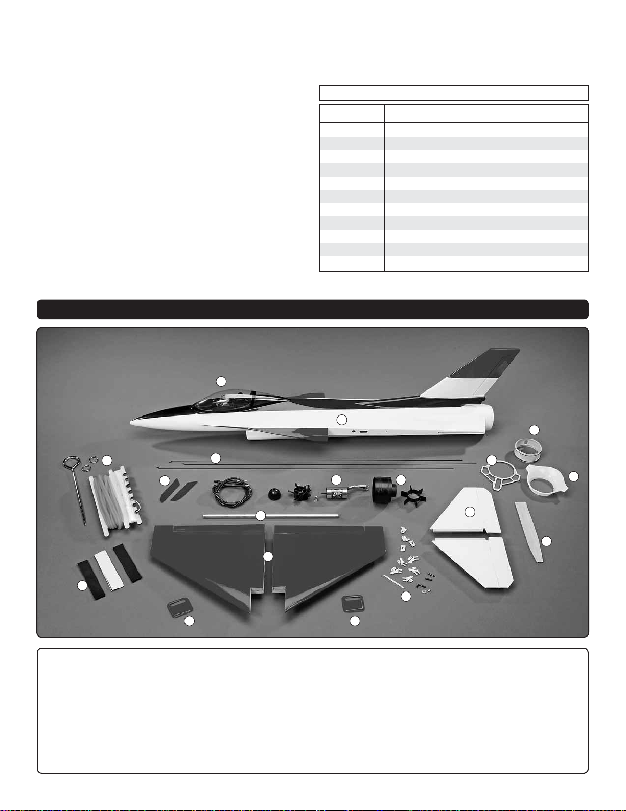
KIT CONTENTS
If additional assistance is required for any reason contact
Product Support by e-mail at productsupport@greatplanes.
com, or by telephone at (217) 398-8970.
REPLACEMENT PARTS LIST
Order No. Description
GPMA4250
GPMA4251
GPMA4252
GPMA4253
GPMA4254
GPMA4255
GPMA4256
GPMA4257
GPMG5185
GPMG3910
GPMA2885
Fuselage F-16 EDF ARF
Wing F-16 EDF ARF
Tail Surfaces F-16 EDF ARF
Cone Adapter F-16 EDF ARF
Front Flange F-16 EDF ARF
Hatch F-16 EDF ARF
Decals F-16 EDF ARF
Bungee Hook F-16 EDF ARF
Ammo 24-45-3790 In-Runner Brushless Motor
Hyperflow 370 EP Ducted Fan w/o Motor
Bungee Launcher Set
5
11
1. Fuselage
2
8
9
10
3
12 12
7. Hyperfl ow Fan (EDF)
1
15
6
7
4
13
14
16
17
13. Hardware
2. Canopy Hatch
3. Wing Panels
4. Horizontal Stabilizers
5. Bungee Launch
6. Ammo Motor
8. Pushrods
9. Grip Tape
10. Wing Tube
11. Hook & Loop
12. Aileron Servo Covers
5
14. Tail Cone Adapter
15. Plywood Former
16. Front Housing Flange
17. Fin Cover
ASS EM BLY IN STRUCTIO NS
NO
Fan Rotor Adapter
(Brass)
Motor
Shaft
The adapter is
not all the way on.
The adapter is
all the way
down onto the
motor shaft up
to the threads.
YES
S
OT
will allow removal of the motor without having to remove the
brass fan adapter.
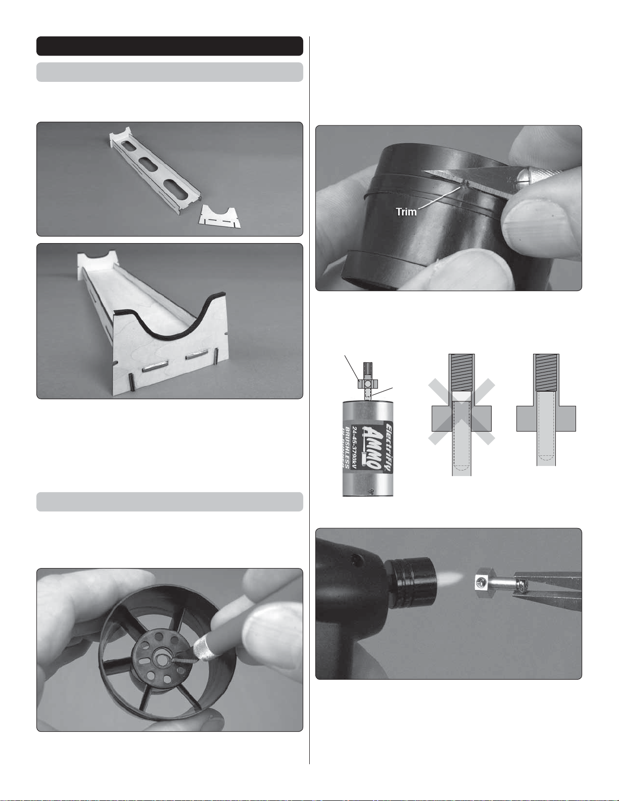
Assemble the Stand
The included plywood stand is used to support your F-16
during assembly and transport.
3. As shown in the HyperFlow manual, trim the three
❏
alignment guides from inside the fan housing. (Also as noted
in the HyperFlow manual, a rotary tool with a sanding drum
makes this easier.)
4. Trim any fl ashing from around the fan housing so the
❏
fi berglass cone adapter will fi t well.
Test-fi t, then glue together the plywood parts of the stand as
shown in the photos. The stand may be used as-is, or you
could add foam tape cut into 1/8" [3mm] wide strips that can be
adhered to the forward and aft saddles. The foam will adhere
best if you fi rst sand the edges of the stand, then seal with
medium CA before applying the foam.
Prepare the HyperFlow Fan Unit
1. Review steps 1 through 6 for Installing a Brushless
❏
Motor on pages 6 and 7 of the separate HyperFlow instruction
manual, but don’t perform any of the steps yet.
2. Enlarge the hole in the fan housing as shown. Once the
❏
fan unit and motor have been installed in the fuselage, this
P
FLAT
5. Press the brass fan rotor adapter onto the motor shaft—
❏
make sure one of the set screw holes in the adapter is aligned
with the fl at spot on the shaft and make certain the adapter
goes on all the way up to the threads. If you can’t get the
adapter to go all the way, use a hobby torch to heat the adapter
fi rst. Then, slide it into the shaft.
6
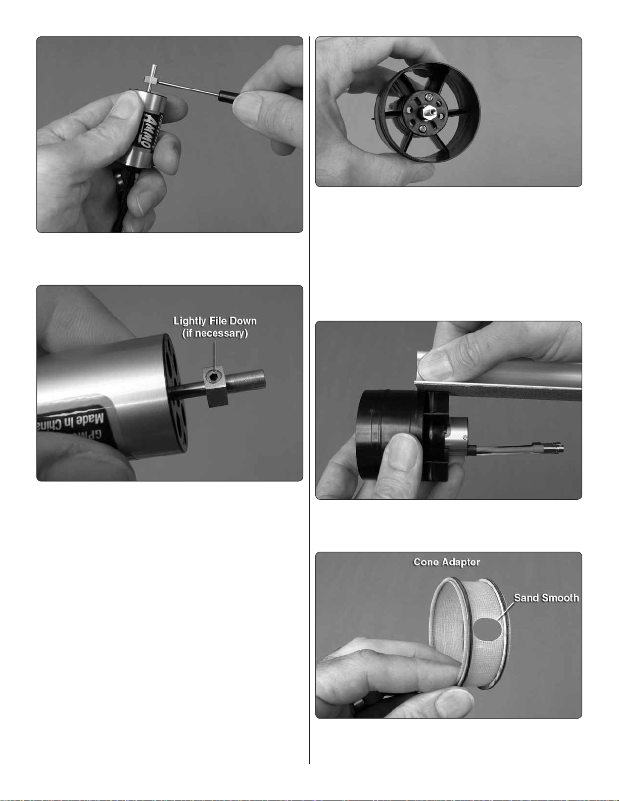
6. Add a small drop of threadlocker to the threads on the
❏
set screws for the adapter. Then, use a quality 1.5mm Allen
wrench to tighten set screws.
10. Mount the motor to the fan housing–you can use the
❏
3 x 5mm screws included with the Ammo motor (and a drop
of threadlocker on the threads). Any set of holes in the fan
housing that align with the holes in the motor may be used,
but we used the outer holes in the motor. Use care not to
overtighten the screws so much that you damage the plastic.
11. Glue the stator extension to the fan housing as shown
❏
in the HyperFlow manual. Make sure the little notches in the
stator fi t around the housing.
7. Test fi t only the fan rotor to the rotor adapter. If the head
❏
of the set screw opposite the fl at spot is protruding from the
adapter and making it diffi cult to install the fan rotor, cover the
front of the motor with a cloth or paper towel and use a metal
fi le to fi le down the screw so the fan will fi t properly.
8. Test mount the fan rotor to the adapter with the rotor
❏
cone, the 3mm Phillips screw and the 3mm washer that came
with the fan unit—the HyperFlow instructions specify using
a 3mm x 8mm screw, but the 3 x 5mm screw included with
the fan may be used.
Hint: For optimal performance it is desirable for the fan rotor
to turn as concentrically (“true”) as possible. T est fi t the rotor
in different orientations around the adapter, spinning it b y hand
each time. When y ou fi nd the orientation that is the truest, use
a hobby knife to lightly scratch a small “X” at the base of the
rotor where it aligns with the fl at spot on the motor. When you
mount the rotor later, do so in this orientation.
9. Remove the cone and rotor and set them aside.
❏
12. Lightly sand the edge of each blade on the stator
❏
extension to remove any fl ashing and to make sure they are
even with the fan housing.
13. Use medium-grit sandpaper to smooth the rough edges
❏
around the motor wire hole in the fi berglass tail cone adapter
so it won’t damage the motor wires.
7
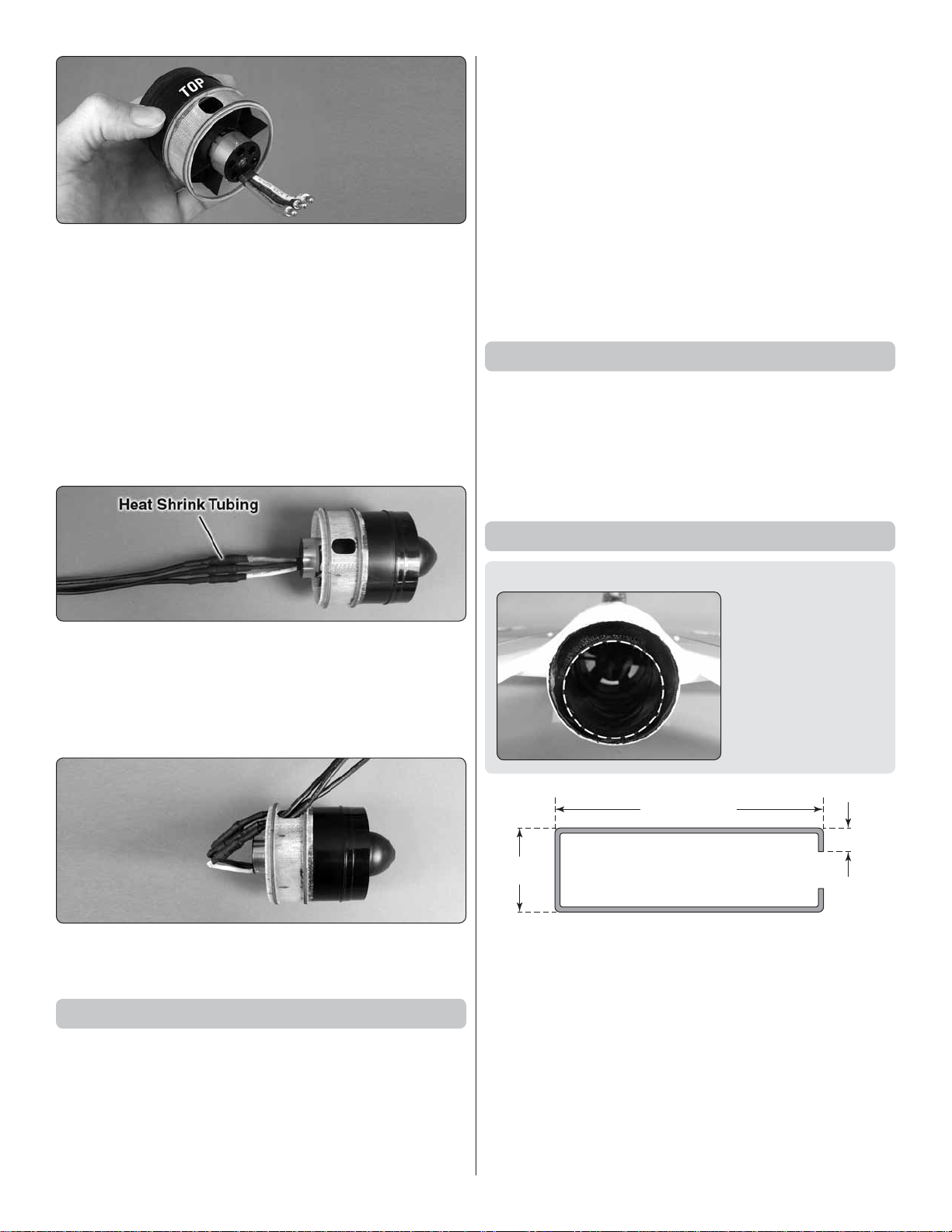
14. Test fi t but do not glue the cone adapter to the rear of
ROTOR PULLER
1" [25mm]
3-1/2" [90mm]
1/4" [6mm]
❏
the fan housing. Note that the hole in the housing should be
180° from the side of the motor where the wires exit—this will
be the top of the unit. Once you have the housing and adapter
mated correctly, permanently glue the two together by adding
a few drops of thin CA to the seam around the outside. Also
apply a few drops of medium CA to each stator blade where
it contacts the inside of the adapter. Note: Apply the CA
sparingly and with care. Otherwise it will run all over the place.
15. Install the fan rotor onto the motor noting the orientation
❏
you marked earlier (for minimal run out)—be certain to use
a small drop of thread locking compound on the 3mm screw.
2. Follow all the precautions and run the motor at no more
❏
than 1/4 throttle as described by the “PREPARE TO RUN
THE FAN” instructions on the back cover of the HyperFlow
fan instructions. (If the motor is turning backwards switch any
two of the motor wires with each other.) Check for vibration
and/or unusual noises and do not proceed until resolving
any problems.
3. Continue with the rest of the break-in procedure until
❏
the system is fully broken-in. Or, if you’re satisfi ed with the
way the unit is performing, stop now and mount the unit in
the fuselage as described in the next section. Be certain to
complete the break-in procedure before fl ying your F-16 for
the fi rst time.
Surface Preparation
There are several steps in this manual that require you to
glue parts to the fi berglass fuselage. Anytime this is done,
the fi berglass should fi rst be cleaned with a cloth dampened
with denatured alcohol, sanded with 220 grit sandpaper, then
cleaned again with denatured alcohol. Doing this will ensure
a strong glue bond.
16. Cut the included heat shrink tubing into three equal
❏
lengths. Connect the motor lead extensions to the motor wires.
Slide the heat shrink pieces onto the motor lead extensions
and use a heat source (heat gun or lighter) to shrink the
tubing around the connections in order to prevent them from
becoming inadvertently disconnected.
17. Carefully slide the motor lead wires through the hole
❏
in the top of the cone adapter as shown.
Test Run the Motor/Fan Unit
1. You may perform either a brief test-run of the motor/fan
❏
unit, or do the complete break-in procedure as described on
the back cover of the HyperFlow instruction manual. In either
case prepare to run the motor by connecting the ESC to
your receiver and to the motor wires coming from the motor.
Reverse the throttle channel in your transmitter and turn on
the transmitter. Connect your motor battery to the ESC.
Install the Fan Unit
DESIGNER NOTE: The aft end of the tail cone is not
centered within the aft
end of the fuselage and
this can be seen by
looking at the plane
from the back side. This
is an intentional part of
the design to maximize
fl ight performance of
the aircraft.
It’s a good idea to test fi t the fan without glue so you can
make sure it fi ts properly. Once permanently installed, the
fan unit will not be possible to remove. However, the motor
may be removed by taking off the fan rotor, unscrewing the
motor mounting screws and taking the motor out the back
through the tail cone. Once out the tail cone, the motor wires
can be disconnected. If you can’t get a good enough grip with
your fi ngers to pull the fan rotor off the adapter, make a rotor
puller from an 8-1/2" [215mm] piece of 2-56 pushrod wire
by bending it as shown. Insert the short hooks on the ends
of the puller under the fan hub and pull.
8
 Loading...