

Page 1
™
SPECIFICATIONS
Wingspan:
Wing Area:
Weight:
GLIDER WING
Wing
Loading:
55.5 in
[1410mm]
2
400 in
[25.8 dm2]
28 – 29.5 oz
[795–835 g]
10.1 – 10.6 oz/ft
[31–32 g/dm2]
2
Wingspan:
Wing Area:
Weight:
SPORT WING
Wing
Loading:
31.5 in
[800mm]
219 in
[14.1 dm2]
22.5 – 24.0 oz
[640 –680 g]
14.8 – 15.8 oz/ft
[45–48 g/dm2]
WARRANTY
Great Planes® Model Manufacturing Co. guarantees this kit to
be free from defects in both material and workmanship at the
date of purchase. This warranty does not cover any component
parts damaged by use or modification. In no case shall Great
Planes’ liability exceed the original cost of the purchased kit.
Further, Great Planes reserves the right to change or modify this
warranty without notice.
In that Great Planes has no control over the final assembly or
material used for final assembly, no liability shall be assumed nor
accepted for any damage resulting from the use by the user of
the final user-assembled product. By the act of using the
user-assembled product, the user accepts all resulting liability.
If the buyer is not prepared to accept the liability associated
with the use of this product, the buyer is advised to return
INSTRUCTION
MANUAL
2
2
this kit immediately in new and unused condition to the
place of purchase.
To make a warranty claim send the defective part or item to
Hobby Services at the address below:
Include a letter stating your name, return shipping address, as
much contact information as possible (daytime telephone
number, fax number, e-mail address), a detailed description of
the problem and a photocopy of the purchase receipt. Upon
receipt of the package the problem will be evaluated as quickly
as possible.
Length: 34.5 in
[875mm]
Radio:
4-Channel with 6 micro servos
and standard receiver
Motor, ESC,
Battery
Hobby Services
3002 N. Apollo Dr. Suite 1
Champaign IL 61822 USA
24-33-4040 Ammo
11.1V 1800 – 2200mAh LiPo
™
, 25A ESC
READ THROUGH THIS MANUAL BEFORE STARTING CONSTRUCTION. IT CONTAINS IMPORTANT
INSTRUCTIONS AND WARNINGS CONCERNING THE ASSEMBLY AND USE OF THIS MODEL.
Champaign, Illinois
(217) 398-8970, Ext 5
airsupport@greatplanes.com
© 2011 Hobbico®, Inc. GPMA1581 Mnl
Page 2

TABLE OF CONTENTS
AMA
INTRODUCTION . . . . . . . . . . . . . . . . . . . . . . . . . . . . . . . .2
AMA . . . . . . . . . . . . . . . . . . . . . . . . . . . . . . . . . . . . . . . . . .2
SAFETY PRECAUTIONS . . . . . . . . . . . . . . . . . . . . . . . . .2
ADDITIONAL ITEMS REQUIRED . . . . . . . . . . . . . . . . . . .3
ORDERING REPLACEMENT PARTS . . . . . . . . . . . . . . . .4
KIT INSPECTION. . . . . . . . . . . . . . . . . . . . . . . . . . . . . . . .5
ASSEMBLE THE WINGS . . . . . . . . . . . . . . . . . . . . . . . . . .6
Install the Servos . . . . . . . . . . . . . . . . . . . . . . . . . . . . .6
Hook up the Ailerons . . . . . . . . . . . . . . . . . . . . . . . . . .7
Finish the Wing . . . . . . . . . . . . . . . . . . . . . . . . . . . . . .8
Mark the C.G. (Balance Point) . . . . . . . . . . . . . . . . . .10
ASSEMBLE THE FUSELAGE . . . . . . . . . . . . . . . . . . . . . 11
Install the Landing Gear. . . . . . . . . . . . . . . . . . . . . . . 11
Attach the Horizontal and Vertical Stabilizers . . . . . .11
Install the Servos . . . . . . . . . . . . . . . . . . . . . . . . . . . .12
Assemble the Ducted Fan . . . . . . . . . . . . . . . . . . . . .13
Test Run the Motor. . . . . . . . . . . . . . . . . . . . . . . . . . .15
FINAL PREPARATIONS . . . . . . . . . . . . . . . . . . . . . . . . .17
Mount the Receiver and ESC. . . . . . . . . . . . . . . . . . .17
Check the Control Directions . . . . . . . . . . . . . . . . . . . 17
Check the Control Throws . . . . . . . . . . . . . . . . . . . . .18
Balance the Model (C.G.). . . . . . . . . . . . . . . . . . . . . .18
Identify Your Model . . . . . . . . . . . . . . . . . . . . . . . . . . .19
Charge the Battery . . . . . . . . . . . . . . . . . . . . . . . . . .19
FLYING THE SYNCRO . . . . . . . . . . . . . . . . . . . . . . . . . .19
Find a Suitable Flying Site . . . . . . . . . . . . . . . . . . . . .19
Ground Range Check . . . . . . . . . . . . . . . . . . . . . . . .19
Set a Flight Timer. . . . . . . . . . . . . . . . . . . . . . . . . . . .20
Take Off . . . . . . . . . . . . . . . . . . . . . . . . . . . . . . . . . . .20
Hand-Launch . . . . . . . . . . . . . . . . . . . . . . . . . . . . . . .20
ROG (Rise off Ground) . . . . . . . . . . . . . . . . . . . . . . . 21
Flying . . . . . . . . . . . . . . . . . . . . . . . . . . . . . . . . . . . . .21
Landing . . . . . . . . . . . . . . . . . . . . . . . . . . . . . . . . . . . 21
After Flight . . . . . . . . . . . . . . . . . . . . . . . . . . . . . . . . .21
INTRODUCTION
Thank you for purchasing the Syncro. The Syncro includes
both a “glider” wing and a “sport” wing. With the glider wing,
the Syncro is more stable and forgiving. This configuration
is better suited to beginners and pilots with little flight
experience, giving them more time to think and react. When
you’re ready to graduate from the glider wing, the sport wing
transforms the Syncro into a more nimble, faster “jet-like”
craft perfect for boring holes in the sky!
For the latest technical updates or manual corrections to the
Syncro visit the Great Planes web site at greatplanes.com.
Open the “Airplanes” link, then select the Syncro. If there is
new technical information or changes to this model, a “tech
notice” box will appear in the upper left corner of the page.
Academy of Model Aeronautics: If you are not already a
member of the AMA, please join! The AMA is the governing
body of model aviation and membership provides liability
insurance coverage, protects modelers’ rights and interests
and is required to fly at most R/C sites.
Academy of Model
Aeronautics
5151 East Memorial Drive
Muncie, IN 47302-9252
Tele. (800) 435-9262
Fax (765) 741-0057
modelaircraft.org
IMPORTANT!!!
Two of the most important things you can do to preserve the
radio controlled aircraft hobby are to avoid flying near fullscale aircraft and avoid flying near or over groups of people.
PROTECT YOUR MODEL, YOURSELF
& OTHERS… FOLLOW THESE
IMPORTANT SAFETY PRECAUTIONS
1. Your Syncro should not be considered a toy, but rather a
sophisticated, working model that functions very much like
a full-size airplane. Because of its performance capabilities,
the Syncro, if not assembled and operated correctly, could
possibly cause injury to yourself or spectators and damage
to property.
2. You must assemble the model according to the instructions.
Do not alter or modify the model, as doing so may result in
an unsafe or unflyable model. In a few cases the instructions
may differ slightly from the photos. In those instances the
written instructions should be considered as correct.
3. If you are not an experienced pilot or have not flown
this type of model before, we recommend that you get
the assistance of an experienced pilot in your R/C club for
your first flights. If you’re not a member of a club, your local
hobby shop has information about clubs in your area whose
membership includes experienced pilots.
4. While this kit has been flight tested to exceed normal use,
if the plane will be used for extremely high stress flying, such
as racing, or if an engine larger than one in the recommended
range is used, the modeler is responsible for taking steps to
reinforce the high stress points and/or substituting hardware
more suitable for the increased stress.
We, as the kit manufacturer, provide you with a top quality,
thoroughly tested kit and instructions, but ultimately the
quality and fl yability of your fi nished model depends
on how you build it; therefore, we cannot in any way
guarantee the performance of your completed model,
and no representations are expressed or implied as to the
performance or safety of your completed model.
2
Page 3

ADDITIONAL ITEMS REQUIRED
Adhesives
There are a couple of adhesives recommended for gluing
the special type of foam from which the Syncro is made:
One kind is either foam-safe or regular CA (cyanoacrylate
or “super glue”). CA is best for modelers that already have
experience with it because CA requires special handling. CA
must be used with adequate ventilation and it can harden
quickly, possibly causing some modelers to glue their fingers
to the parts or to each other. Another kind is “canopy glue,”
a craft glue specially formulated for plastics. Canopy glue is
recommended for most builders because it is water soluble,
easy to clean up, emits no fumes and is easier to work with
because it takes longer to dry:
CANOPY GLUES
Zap Adhesives Ric 560 (PAAR3300), OR
❏
J&Z R/C-56 (JOZR5007)
❏
If using canopy, glue Great Planes epoxy brushes (6)
(GPMR8060) are also recommended for spreading the glue.
long as you desire. And the same applies to the 2200mAh
“T-Rex” battery. With this battery the motor draws slightly
more current @ 22 Amps, but will still fall to or below the
maximum rated constant current when in the air. However,
the motor should not be run on the ground with either battery
at full power for more than 30 seconds. Otherwise, the motor
may overheat causing damage.
If using batteries other than the ones recommended, keep
in mind that batteries with higher capacity (mAh) and/or “C”
rating could cause the motor to operate over its maximum
current limit. The recommended 2200mAh 25C battery, is
capable of providing 55 Amps (2.2 Amps x 25 C = 55A). So, if
you were to switch to, say a larger, 2500mAh 25 C battery it
will be capable of 62.5 Amps. This may be okay as long as the
motor does not draw more than 28 Amps, but then the Syncro
should probably not be flown full throttle for extended periods
without lowering the throttle allowing the motor to cool.
If experimenting with batteries different than the ones
recommended, the best way to know if you are operating
the motor within its limits is to connect a Watt meter
(REPL0100) in-line between the ESC and the battery.
This will tell you how much current the motor is drawing
with the battery you are using.
CA AND ACCESSORIES
1 oz. [30g] Medium Pro
❏
2 oz. [57g] spray CA activator (GPMR6035)
❏
CA applicator tips (HCAR3780)
❏
CA debonder (GPMR6039)
❏
™
CA+ (GPMR6008)
Motor and ESC
The motor and ESC (electronic speed control) recommended
for the Syncro are these:
Great Planes 24-33-4040 Ammo Inrunner Brushless
❏
Motor (GPMG5165)
Great Planes Silver Series SS-25 25A Brushless ESC
❏
(GPMM1820)
Note: The recommended 24-33-4040kV Ammo motor is
rated for 18 Amps constant current and 28 Amps surge
current. This means the motor can be run indefinitely as long
as it is not drawing more than 18 Amps, but can be run for no
longer than 30 seconds if drawing the maximum of 28 Amps
before you have to back off the throttle and allow the motor to
sufficiently cool. The closer to 18 Amps the motor operates
the longer it can be run until it gets too hot. And the closer to
28 Amps the motor operates the shorter it may be run until it
gets too hot (again, before reducing the throttle allowing the
motor to cool). The motor must never be operated over 28
Amps. The ElectriFly batteries recommended in this manual
will allow the motor to operate within the specified range:
With the 1800mAh 11.1V (3S) 25C battery, the motor will
draw about 21 Amps on the ground (static) at full-throttle.
Although this is slightly over the constant current limit (of
18 Amps), it will drop to or below this limit when the plane
is in the air, so the Syncro may be flown full-throttle for as
Batteries
There are a couple of batteries recommended for the Syncro.
The ElectriFly 1800mAh 11.1V 25C LiPo (lithium-polymer)
battery (GPMP0515) is smaller, lighter weight and less
expensive, while the ElectriFly 2200mAh 11.1V 25C “T-Rex”
LiPo (GPMG0520) is slightly larger for slightly longer flight time.
Radio Control System
The Syncro requires a 4-channel radio control system with
Futaba S3107 micro servos (or similar). For beginners who
may not already have a suitable radio control system, the
Futaba 6EX 6-channel radio is recommended (FUTK6900).
It features the latest 2.4GHz technology for reliability and
eliminates the need for frequency sharing with other pilots
who may be flying at the same time.
The 6EX does not come with servos, so six servos will also
be required (two for each wing and two for the elevator and
rudder controls in the fuselage). Futaba S3107 micro servos
(FUTM0025) are recommended and illustrated in the manual,
but any servo that is the same size (7/8" x 7/16" x 13/16"
[22mm x 11mm x 20mm]) and torque rating could also be
used. ElectriFly ES-50 Nano servos (GPMM1210) are also
suitable.
A 6" [152mm] servo extension wire (HCAM2000 for Futaba)
will also be required.
3
Page 4
Charging System
ORDERING REPLACEMENT PARTS
The LiPo batteries recommended for your Syncro require a
special charger capable of charging LiPos. LiPo batteries must
also be “balance charged” so that each of the three individual
cells making up the complete battery are charged evenly.
For pilots who wish to charge several batteries
simultaneously (reducing down time and optimizing flight
time), the Great Planes PolyCharge4™ DC-powered LiPo
charger (GPMM3015) is recommended. The PolyCharge4
can charge up to four LiPo batteries at once. But the
PolyCharge4 does not have an internal LiPo cell balancer,
so for each LiPo battery you wish to charge simultaneously,
one Great Planes Equinox™ LiPo Cell Balancer (GPMM3160)
will also be required. Finally, the PolyCharge4 does not have
AC capability, so if wall-charging from home is important,
a separate A/C 12-Volt power source must be purchased
separately. A suitable power supply for the PolyCharge4 is
the Great Planes 12V 12A DC power supply (GPMP0901).
Another viable battery charging option is the Triton™ EQ
(GPMM3155) featuring the required built-in LiPo cell
balancing. The Triton EQ also features a built-in AC adapter
and wall cord so it can charge batteries from either a wall
outlet or a 12V source. The Triton EQ can charge only one
battery at a time.
Replacement parts for the Syncro are available using the
order numbers in the Replacement Parts List that follows.
The fastest, most economical service can be provided by
your hobby dealer or mail-order company.
To locate a hobby dealer, visit the Great Planes web site
at greatplanes.com. Choose “Where to Buy” at the
bottom of the menu on the left side of the page. Follow the
instructions provided on the page to locate a U.S., Canadian
or International dealer.
Parts may also be ordered directly from Hobby Services
by calling (217) 398-0007, or fax at (217) 398-7721, but full
retail prices and shipping and handling charges will apply.
Illinois and Nevada residents will also be charged sales tax.
If ordering via fax, include a Visa
and expiration date for payment.
Mail parts orders and payments by personal check to:
Hobby Services
3002 N. Apollo Drive, Suite 1
Champaign, IL 61822
Be certain to specify the order number exactly as listed in
the Replacement Parts List. Payment by credit card or
personal check only; no C.O.D.
®
or MasterCard® number
Tools and Accessories
Other than common hobby tools such as screwdrivers,
needle-nose pliers, etc., here is the list of items illustrated
in this instruction manual required to assemble the Syncro.
Thread-locking cement (GPMR6060)
❏
Great Planes stick-on lead weight (GPMQ4485)
❏
Masking tape
❏
A standard “L-bend” hex key is included with this kit for
tightening the set screws in the fan rotor adapter (see
page 13), but it’s really only a “one-time” use tool. For any
future disassembly and reassembly, and even for this firsttime assembly, a high-quality 1.5mm hex wrench such as
the DuraTrax® 1.5mm Ultimate Hex Driver (DTXR0288) is
suggested.
If additional assistance is required for any reason, contact
Product Support by telephone at (217) 398-8970, or by
e-mail at productsupport@greatplanes.com.
REPLACEMENT PARTS LIST
Order No. Description
GPMA4190
GPMA4191
GPMA4192
GPMA4193
GPMA4194
GPMA4195
GPMA4196
GPMA4197
GPMA4198
GPMA4199
NOTE
Fuselage Set
Glider Wing Set
Sport Wing Set
Tail Set
Foam Fan Duct
Landing Gear Set
Hardware Pack
Canopy Hatch
Ducted Fan Unit
Ducted Fan Rotor
Full-size plans are not available.
You can download a copy of this
manual at www.greatplanes.com.
4
Page 5
KIT INSPECTION
Before starting to build, take an inventory of this kit to make sure it is complete, and inspect the parts to make sure they
are of acceptable quality. If any parts are missing or are not of acceptable quality, or if you need assistance with assembly,
contact Product Support. When reporting defective or missing parts, use the part names exactly as they are written in the
Kit Contents list.
Great Planes Product Support:
3002 N Apollo Drive, Suite 1
Champaign, IL 61822
Telephone: (217) 398-8970, ext. 5
Fax: (217) 398-7721
E-mail: airsupport@greatplanes.com
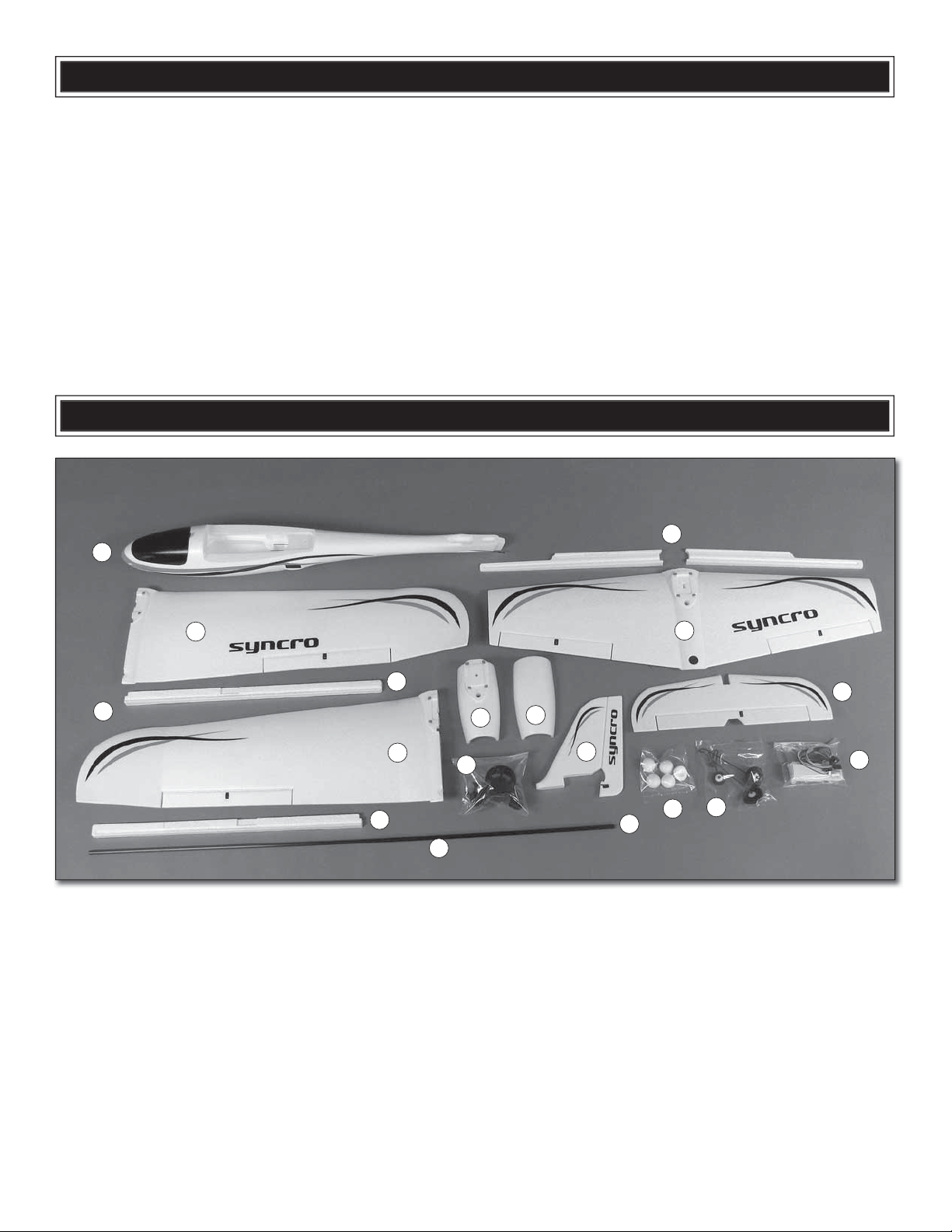
KIT CONTENTS
1
2
17
1. Fuselage/canopy hatch
2. Glider wing halves (R&L)
3. Glider wing spar
4. Glider wing spar covers
5. Jet wing
6. Jet wing spar covers
7. Horizontal stabilizer with elevators
8. Vertical stabilizer with rudder
9. Fan duct (top, bottom)
10. Fan assembly (fan housing, rotor, tail cone)
11. Foam fan cones (5)
6
5
4
9
2
10
4
16
9
8
12
11
3
12. Landing gear (R&L main landing gear, 40mm wheels,
nose gear, 25mm nose wheel)
13. Hardware (Glider wing dowel plate, adhesive-back hook
& loop (2), long (450mm) Y-harness, short (240mm)
Y-harness, motor wire extensions, aileron pushrods, Fan
duct mounting bolt, wing bolt collar, Phillips wing screw,
pinned hinge, 10mm wood screws (2), 3mm fl at washer (for
wing screw), micro screw-locks (4), Faslinks (6), retainers
for screw-locks (6), screws for screw-locks (8),
rotor adapter w/set screws, 5mm hex nut, 3x4mm fl athead motor mount screws (2)
7
13
2mm fan
5
Page 6
ASSEMBLE THE WINGS
After the spar covers are permanently glued into place,
the ends of the Y-connector for the aileron servos will no
longer be accessible. The servos may still be removed by
pulling the wires out of the wing, but the wing will no longer
be functional because it will not be possible to re-connect
new servos. So make sure your servos are working properly
before permanently gluing in the spar covers because
there’s no going back.
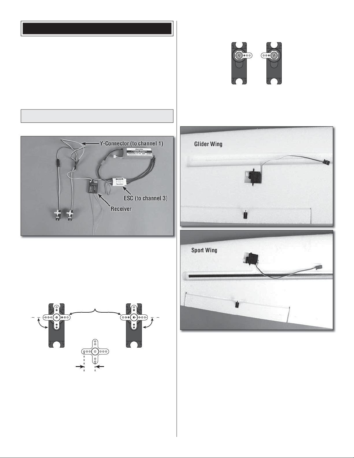
Install the Servos
Refer to this photo for the next two steps.
Cut off the unused arms
3. Use small wire cutters to cut off the unused arms so
❏
you have two, opposing servo arms. Fasten the arms to the
servos with the servo arm screws that came with your servos.
1. If assembling the glider wing, connect the two servos
❏
you will be using for the ailerons to the longer Y-connector. If
assembling the sport wing, connect the aileron servos to the
shorter Y-connector. Connect the ESC to the throttle channel
in the receiver (channel 3 for Futaba) and the Y-connector to
the aileron channel (channel 1). (If using the ElectriFly SS25 ESC, note that the brown wire is the negative lead.)
Longer, 3-hole arms
90°
5/16" [8mm]
2. Turn on your transmitter and center the trims. Connect
❏
the motor battery to the ESC to power the servos. Use servo
arms with holes that are approximately 5/16" [8mm] from
center (which are the arms included and shown for the
Futaba servos recommended). Position the arms on the
servos so they will be 90°, or as close to 90° as possible to
the sides of the servo.
90°
4. Disconnect the servos from the Y-connectors. Test-
❏
fi t, then glue the servos into the wings as illustrated for the
wing you are working on: It is recommended to use canopy
glue because the servos will be easier to remove later if ever
necessary (for transferring to another model). Hint: You can
skip ahead to step 1 on page 12 and glue in the elevator and
rudder servos too. Then, you won’t have to wait for the glue to
dry when you get to that part of assembly.
6
Page 7
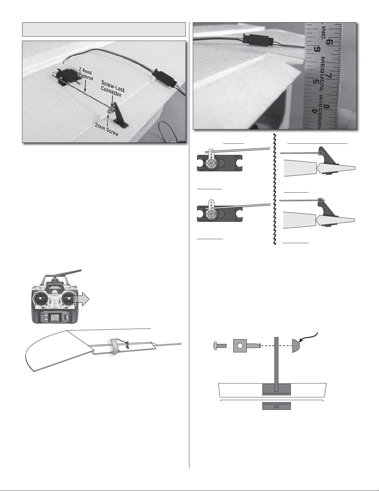
Hook up the Ailerons
1. If working on the glider wing (pictured), connect one of
❏
the shorter Z-bend pushrods to the outer hole of the servo
arm on the servo in the right wing panel. Insert a screw-lock
connector into the bottom hole in the aileron control horn
and fi t the pushrod into the connector.
If working on the sport wing, connect one of the longer
Z-bend pushrods into the outer hole of the servo arm on
the servo in the right side of the wing. Insert a screw-lock
connector into the outer hole in the aileron control horn and
fi t the pushrod into the connector.
2. Same as when you were fi tting the servo arms to the
❏
servos, temporarily connect the aileron servo to the receiver
and power up the system so you can move the servo with
the transmitter. Holding the aileron centered, temporarily lock
the pushrod to the screw-lock connector with a 2mm screw.
Move the aileron control
stick to the right
SERVO CONTROL SURFACE
Moving the pushrod outward
increases the control throw
Moving the pushrod inward
decreases the control throw
Move the aileron stick all the way to the right. Measure how
far from center the trailing edge of the aileron moved. For the
glider wing, the aileron should move 3/8" [10mm] up and
3/8" [10mm] down. For the sport wing, the aileron should
move 5/16" [8mm] up and 5/16" [8mm] down. If the aileron
does not move the specifi ed distance, move the pushrod
to another hole in the servo arm or to another hole in the
aileron horn to increase or decrease the throw until you can
get it as close as possible (+/- 1/16" [1.5mm] is acceptable).
Moving the pushrod inward
increases the control throw
Moving the pushrod outward
decreases the control throw
Right aileron deflects
toward the top of the wing
3. Use the control stick on the transmitter to move the
❏
aileron servo. Make sure the servo is moving in the correct
direction; when you move the stick to the right the aileron
should defl ect toward the top of the wing (downward, since
we are working on the wing upside-down). If the aileron
does not respond in the correct direction, reverse the servo
direction in the transmitter.
4. Once we’ve confi rmed that the servo direction is
❏
correct, check the control throw as follows to make sure the
model responds correctly in the air—if the throw is too much
you will end up over-controlling it—if the throw is not enough
the model will respond too slowly.
Retainer
5. Once you have the pushrods where you want them and
❏
the control throw set, press a nylon retainer onto the screw-
lock connector securely holding it to the control horn—be
certain the retainer fi ts tightly and goes all the way on. If you
feel the retainer slipped on too easily, discard that retainer
and replace it with another—a couple of spare retainers are
included with this kit.
7
Page 8
6. Still with the radio on, remove the screw in the screw-
❏
lock connector, wet the threads with threadlocker, reinstall
the screw and tighten it securely making sure the aileron
remains centered.
7. Connect the other pushrod to the other aileron and
❏
servo the same way.
Finish the Wing
GLIDER WING:
1. Keep a couple of paper towels handy for wiping glue
❏
from your fi ngers and the wing—remember, canopy glue is
preferred because it will be easier to clean up. You’ll also
need some masking tape for holding the halves together
until the glue dries. If using canopy glue, lightly wet the
paper towels with water or window cleaner to make it easier
to wipe up glue.
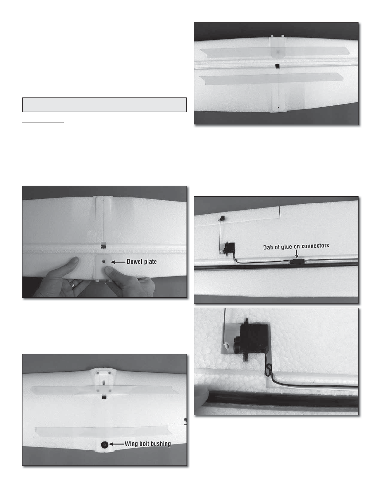
4. Mate the halves and install the dowel plate. Use strips
❏
of masking tape on the top and bottom of the wing to pull
the halves together. Make certain the dowel plate remains
in position helping to keep the wings aligned. Also install
the wing bolt bushing to align the trailing edges. Use your
paper towels to wipe excess glue from the wing and from
your fi ngers as necessary. Do not disturb the wing until the
glue has set (overnight if using canopy glue).
2. Test-fi t the wing halves using the dowel plate to help
❏
assure alignment.
3. Get ready to glue the wings together. Apply glue to all
❏
joining surfaces of both wing halves—you don’t need much—
just a fi lm, but all surfaces that touch should have glue.
5. After the glue from joining the wing halves has dried,
❏
remove the masking tape and get ready to glue in the spar
and the spar covers. Test-fi t, but do not glue in the spar. Also
connect the Y-connector to the servos. Use a dab of glue to
hold the connectors in the channel so they won’t move around
and interfere with the fi t of the spar covers. If the servo wires
are too long you can double them back into the servo cavity.
8
Page 9

6. Test-fi t, but do not glue in the spar covers. Once you see
❏
that the spar and spar covers fi t well, remove and apply glue all
the way around the spar—an epoxy brush is great for spreading
the glue. Place the spar in the wing. Coat the channel and the
spar covers with glue, then fi t them into the wing.
7. Wipe away excess glue with paper towels and make
❏
certain the spar covers remain in position until the glue
dries—they shouldn’t require clamps or tape, but just
monitor the spar covers for a few minutes pressing them
back down into the wing if necessary. After a few minutes the
glue should set well enough to hold them into position until
you can handle the wing after the glue has completely dried.
SPORT WING:
1. Connect the short Y-connector to the aileron servo wires.
❏
Use a drop of glue to hold the connectors in the channel so
they won’t move around and interfere with the fi t of the spar
covers when gluing them in.
2. Test fi t the spar covers—they should fi t all the way down
❏
until they are fl ush and even with the bottom of the wing.
3. Remove the spar covers. Apply glue to one of the spar
❏
covers and in the corresponding channel in the wing—make
especially sure that you get glue on the spar and in the
groove in the spar cover for the spar. Hint: An epoxy brush
will make it easier to evenly distribute the glue.
4. Insert the spar cover and wipe away excess glue with
paper towels. Glue in the other spar cover the same way.
Wipe away excess glue with paper towels and make certain
the spar covers remain in position until the glue dries—they
shouldn’t require clamps or tape, but just monitor the spar
covers for a few minutes pressing them back down into the
wing if necessary. After a few minutes the glue should set
well enough to hold them into position until you can handle
the wing after the glue has completely dried.
9
Page 10

Mark the C.G. (Balance Point)
GLIDER WING:
4" [102mm]4" [102mm]
Balance Lines
SPORT WING:
4" [102mm] 4" [102mm]
Balance Lines
2-3/4" [70mm]
2-1/2" [64mm]2-1/2" [64mm]
2-3/4" [70mm]
2-3/4" [70mm]
2-1/4" [57mm]
1. Use a fi ne-point felt-tip pen to mark the balance lines
❏
2-3/4" [70mm]
2-1/4" [57mm]
on the bottom of the wing 4" [102mm] out from them middle
of the wing and 2-1/2" [64mm] back from the leading edge
where shown. Mark two more lines 1/4" [6.4mm] ahead and
1/4" [6.4mm] behind the lines you marked.
3-1/8" [79mm]
2-3/8" [60mm]
1. Use a fi ne-point felt-tip pen to mark the balance lines
❏
3-1/8" [79mm]
2-3/8" [60mm]
on the bottom of the wing 4" [102mm] out from them middle
of the wing and 2-3/4" [70mm] back from the leading edge
where shown. Mark two more lines 3/8" [10mm] ahead and
3/8" [10mm] behind the lines you marked.
2. Apply narrow strips of tape approximately 1/16"
❏
[1.5mm] wide over the lines so you will be able to feel them
with your fi ngers when balancing the plane later. If you don’t
have any narrow tape you could simply cut whatever tape
you do have into strips.
2. Apply narrow strips of tape approximately 1/16"
❏
[1.5mm] wide over the lines so you will be able to feel them
with your fi ngers when balancing the plane later. If you don’t
have any narrow tape you could simply cut whatever tape
you do have into strips.
10
Page 11

ASSEMBLE THE FUSELAGE
Install the Landing Gear (Optional)
The landing gear for the Syncro is optional. If you prefer the
streamlined appearance of a glider (with the glider wing) or the
jet-like appearance with the landing gear retracted (with the
sport wing) you may simply leave the landing gear off. Of course
your Syncro will then have to be hand-launched and landed on
soft terrain so as not to damage the bottom of the fuselage.
Press-fi t the main and nose landing gear into the molded-
❏
in landing gear mounts. It doesn’t matter which way the main
gear goes in (there isn’t a right or a left), but the nose gear
should be installed with the wire “bending” back as illustrated.
Attach the Horizontal and
Vertical Stabilizers
2. Temporarily fi t the vertical stabilizer (fi n) to the horizontal
❏
stabilizer (stab) and fi t the assembly to the fuselage. Also
temporarily fi t the pushrods into the middle holes of each
control horn. If necessary, carefully use a sharp hobby knife
to enlarge the holes in the horns so the pushrods will fi t.
3. Remove the pushrods from the horns and separate the
❏
fi n and stab from the fuselage and from each other.
1. Bend the elevator up and down several times to free up
❏
the hinge. Do the same with the rudder.
4. The fuselage will be easier to work on if the battery is in
❏
position to hold the nose down, so apply the softer, “loop” side
of the included hook-and-loop material to your battery.
11
Page 12

5. Apply the rougher, “hook” side to the bottom of the
❏
battery compartment inside the fuselage. (If more Velcro is
ever required for more batteries, you can purchase Great
Planes adhesive-back Velcro separately (GPMQ4480)—or,
you could cut the included strip in half and have enough for at
least two batteries.)
8. Remove the wing. Test-fi t, then glue the pinned hinge
❏
into the bottom of the rudder and the fuselage—use care not
to get any glue into the hinge pin. As a precaution, you could
add a dab of petroleum jelly or plastic-compatible oil to the
hinge joint. Note: if the rudder control horn down inside the
rudder interferes with the fi t of the hinge keeping it from going
all the way in, it’s okay to nip a little corner off the hinge to
clear the horn.
Install the Servos
6. For alignment purporses, temporarily mount one of the
❏
wings to the fuselage with the 1-3/8" [35mm] Phillips sheet
metal screw and washer.
7. Apply glue to all joining surfaces and fi t the fi n and stab
❏
into position. (Again, using canopy glue will make clean up
easier with damp paper towels.) Working quickly, see if the
stab is parallel with the wing. If necessary, align the stab with
the wing and do not disturb the assembly until the glue dries.
1. The same as was done with the aileron servos, glue
❏
the elevator and rudder servos into position.
12
Page 13

2. Fit the pushrods into the middle hole in the elevator
❏
control horn and into the lowest hole—the one closest to the
surface of the rudder—in the rudder control horn. Secure the
pushrods with micro Faslinks—sometimes it’s easiest fi rst
to slide the Faslinks over the pushrods, then to insert the
pushrod in the control horn. Then, holding the Faslink on the
pushrod, slide the Faslink forward and fi t it over the L-bend
in the pushrod.
Assemble the Ducted Fan
1. Remove the female “bullet” connectors from the ducted
❏
fan motor (not included). These will not be used because
the recommended SS-25 ESC already has connectors on
the wires.
Flat Spot
1/2" [12mm–13mm]
Cut off the unused arms
3. Prepare the servo arms for the elevator and rudder
❏
servos—this time, make a 1/2" [12mm – 13mm] servo arm
for the rudder so you can get the correct control throw.
Rudder Elevator
2. Fit the brass fan adapter shaft over the motor shaft—be
❏
certain one of the two holes in the adapter for the set screws
is aligned over the fl at spot on the motor shaft. Also be certain
the adapter is pressed all the way onto the motor shaft.
4. Fasten the screw-lock connectors to the servo arms
❏
where shown with the retainers and temporarily lock the
pushrods to the retainers with the small screws.
3. Barely wet the threads of both 3mm set screws with
❏
threadlocker and thread them into the adapter. Making sure
the longer of the two set screws goes over the fl at spot on
the motor shaft, use the included 1.5mm hex key wrench (or
a high-quality hex key wrench as recommended in the front
of the manual) to tighten the screws.
13
Page 14

4. Use a hobby knife to enlarge the hole in the fan housing
❏
to accommodate the adapter shaft on the motor.
6. Fit the fan onto the adapter shaft keying the notches in
❏
the back of the fan over the set screws protruding from the
shaft. Make certain the fan is all the way down onto the shaft—
if you can thread the nut over the shaft with a little of the shaft
protruding from the nut, then the fan is all the way on.
7. Remove the nut, add a drop of threadlocker to the
❏
threads, then install and tighten the nut with an 8mm or 5/16"
wrench or pliers.
5. Use threadlocker to wet the threads of both 3mm fl at-
❏
head Phillips screws and mount the motor in the fan housing
with the screws through the slotted holes. Note that the wires
coming out of the back of the motor should be perpendicular
to the mounting tabs on the housing. The side with the wires
will be the “top” of the unit.
8. OPTIONAL: The optional tail cone may provide
❏
a few additional miles-per-hour, but it won’t be anything
monumental. If you prefer not to take the time to install the
tail cone simply skip this step. To install the cone, cut a slot
in the cone to accommodate the motor wires, then tack-glue
14
Page 15

it into position with four to six drops of medium CA. Note that,
if ever the motor requires removal, the tail cone will have to
be broken free from the fan housing. This should not prove to
be diffi cult as long as it was just tack-glued into place.
Test Run the Motor
Before mounting the fan cone and proceeding with the rest
of assembly, test-run the motor to make sure everything is
working properly. You’ll need your transmitter, receiver, ESC
and battery again.
1. If you haven’t yet done so, charge your motor battery
❏
following the instructions, warnings and cautions included
with the battery and charger.
9. Connect the three motor extension wires to the motor
❏
wires coming from the motor and guide them down through
the hole in the bottom half of the fan duct while simultaneously
keying the fan housing into position. Secure the housing to
the duct with the two small Phillips-head screws.
2. Temporarily connect the three motor wires coming from
❏
the ESC to the three motor extension wires coming from
the motor. Connect the ESC to the throttle channel in the
receiver (channel 3 for Futaba).
3. Turn on your transmitter. If using the ElectriFly SS-25
❏
ESC set the throttle servo direction in your transmitter to
“reverse” (this is channel 3 for Futaba).
4. Be certain the throttle stick on your transmitter is all the
❏
way down. Connect the battery to the ESC. With the top of the
fan duct in position, hold the unit in one hand and advance
the throttle stick just enough to get the motor to turn. Make
certain the motor is turning in the correct direction by checking
to see that air is blowing out the back of the fan. If the fan is
turning the wrong way, disconnect the battery and swap any
two of the three motor wires with each other. With the throttle
stick all the way down, re connect the battery and operate the
motor to confi rm that it is turning in the correct direction.
15
Page 16

CAUTION: In the next step we will be running the fan
to full power, so proceed with great care and wear
hearing protection and eye protection.
5. Once you have confi rmed that the motor is running
❏
in the correct direction, put on your hearing protection and
safety glasses. Advise anybody else in the area to do the
same (or ask them to leave the area).
6. Firmly holding the fan duct in your hand, point the
❏
intake away from anything that could get sucked into it and
point the exhaust in an area where nothing will get blown
off the workbench or blown around the room. Checking your
surroundings, advance the throttle to about 1/3 stick. If the
motor and fan run smoothly hold the throttle in this position for
one minute. Continue the test-running procedure as described
step 10. If you detect any unusual noise or vibration cut the
throttle, disconnect the battery and turn off the transmitter.
10. Once you can get the motor and fan to run smoothly
❏
at 1/3-throttle for one full minute, advance the throttle to 2/3
stick and run for another minute, then fi nally to full power for
30 seconds.
11. After you have confi rmed smooth operation of the
❏
motor and fan unit all the way to full-throttle, disconnect the
battery, ESC and receiver. Use a few drops of CA or canopy
glue to tack glue one of the foam fan cones to the fan.
7. With the power disconnected, remove the top of the fan
❏
duct and inspect the fan and housing for any signs of rubbing
or wear. If necessary, remove the fan and use a hobby knife
to remove any plastic that may have been deposited on the
fan blades or in the housing. If you can’t pull the fan off with
your fi ngers, you can make a “fan puller” from 1/16" [1.6mm]
pushrod wire as shown.
8. Remount the fan 180° from the way it was, then reinstall
❏
the nut with threadlocker. Run the motor as described in step 6
to see if the problem has been solved. If there is still vibration
or rubbing, remove the fan again. This time also remove the
adapter shaft from the motor—this will also require removal
of the motor from the fan housing. (Or you could drill a 3/32"
[2.4mm] hole through the housing 5/8" [16mm] back from the
front edge. Then, you can insert your hex key wrench down
through the hole instead of removing the motor.)
12. Guide the motor wires down through the hole in the
❏
wing and attach the fan duct to the top of the wing with the
magnets.
9. Reinstall the adapter shaft onto the motor 180-degrees
❏
from the original position and remount the fan with the nut.
Once more run up the motor to 1/3-throttle.
13. Secure the fan duct to the wing with the nylon bolt.
❏
16
Page 17

FINAL PREPARATIONS
Mount the Receiver and ESC
1. Apply the remaining “hook” side of the included hook-
❏
and-loop strip to the bottom of the fuselage in the radio
compartment in front of the servos. Connect a 6” [150mm]
servo extension in the aileron channel in your receiver (so
it will be easier to connect and disconnect the aileron servo
wire when installing/removing the wing). Connect the rest
of the servos and the ESC to the receiver and mount the
receiver and ESC in the bottom of the fuselage with the
other side of the hook-and-loop.
2. Turn on the transmitter and receiver. Add a drop of
❏
threadlocker to the 2mm screws in the screw-lock connectors
on the elevator and rudder servos and lock the pushrods
down making sure the elevator and rudder are centered.
4. Place the wing on the fuselage making sure none of
❏
the wires are pinched between the bottom of the wing and
the fuselage. Bolt the wing to the fuselage with the 35mm
Phillips sheet metal screw and the 3mm washer—do not
over-tighten the screw—just about 1 to 1-1/2 turns after the
bolt is seated on the collar.
Check the Control Directions
The instructions already guided you how to set up the
controls, but it is always a good idea to double-check that
the controls are responding in the correct direction once the
model is all together. With the wing mounted to the fuselage
turn on the transmitter, then connect the battery.
4-CHANNEL RADIO SET UP
(STANDARD MODE 2)
3. Connect the three motor wires coming out of the wing
❏
to the three wires coming from the ESC and connect the
Y-connector for the ailerons coming from the wing to the
servo extension in the aileron channel in the receiver. Before
mounting the wing to the fuselage, turn on the transmitter
and connect the battery to the ESC. Run the motor briefl y to
make sure it is running in the correct direction—it should be
blowing air out the back. If the motor is turning the wrong way,
same as before when conducting initial test runs, swap any
two of the motor wires to get the motor running the right way.
RIGHT AILERON
RUDDER
MOVES
RIGHT
FULL
THROTTLE
Confi rm that the controls are responding in the correct
direction as illustrated.
17
MOVES UP
LEFT AILERON
MOVES DOWN
ELEVATOR
MOVES DOWN
Page 18

Check the Control Throws
Balance the Model (C.G.)
You were also already guided how to connect the pushrods
to get the recommended throws, but because the control
throw has such a great effect on how a model fl ies the throws
should be checked again. You should also program the lowrate throws so you can switch between rates in-fl ight to suit
your taste and the conditions.
It is best to get the throws as close as possible to the
recommended measurements specifi ed below fi rst by
relocating the pushrods on the servo arms and/or on the
control horns on the control surfaces. Once the throws are
close, then you can adjust the end points or ATV’s in your
transmitter as necessary. Moving the pushrods inward on
the servos or outward on the control surfaces will provide
less throw. Moving the pushrods outward on the servos or
inward on the control surfaces will provide more throw.
These are the recommended control surface throws:
HIGH RATE LOW RATE
ELEVATOR
Up
3/8"
[10mm]
17°
Down
3/8"
[10mm]
17°
Up
1/4"
[6.5mm]
11°
Down
1/4"
[6.5mm]
11°
The C.G. (Center of Gravity) is the location on the wing
where the model balances. Same as the control throws,
the C.G. has a profound effect on the way the model fl ies.
If the C.G. is too far aft (tail heavy), the model will be too
responsive. If the C.G. is too far forward (nose-heavy), the
model will not be responsive enough. Follow the balance
procedure to make sure the model is properly balanced
and the C.G. is in the correct location.
IMPORTANT! If balancing your Syncro with the Sport
wing, it will have to be re balanced again if you install the
Glider wing. And the same is true for the opposite—be
certain to re balance your Syncro after switching wings.
1. On page 10 you were already instructed to mark the
❏
balance lines on the bottom of the wings. Mount the wing
and Install the motor battery. All the rest of the parts of the
model should be installed including the fan duct with the
motor, landing gear, battery hatch and all the servos and
radio components.
Right
RUDDER
AILERONS
(Glider Wing)
AILERONS
(Sport Wing)
Note that the aileron throws for the glider wing and the
sport wing are different, but all the rest of the throws are
the same for both models.
5/8"
[16mm]
22°
Up
3/8"
[10mm]
18°
Up
5/16"
[8mm]
13°
Left
5/8"
[16mm]
22°
Down
3/8"
[10mm]
18°
Down
5/16"
[8mm]
13°
Right
3/8"
[10mm]
13°
Up
1/4"
[6.5mm]
12°
Up
3/16"
[5mm]
8°
Left
3/8"
[10mm]
13°
Down
1/4"
[6.5mm]
12°
Down
3/16"
[5mm]
8°
2. Place your fi ngers on the middle balance lines and
❏
lift the model. If the fuselage remains level (balances), your
Syncro is perfectly balanced—it may be helpful to have an
assistant view the model from the side if you can’t tell for sure.
If the fuselage does not rest level try moving your fi ngers
under the wing, making certain to keep them between the
forward and aft lines. If you can get the fuselage to rest
level with your fi ngers between the forward and aft balance
lines, it is within the recommended balance range and could
be fl own, but it’s really best to get the model to balance
directly on the middle lines as recommended. This is where
the Syncro will fl y best. Balance the model as instructed in
the following steps.
18
Page 19

Identify Your Model
No matter if you fl y at an AMA sanctioned R/C club site or
if you fl y somewhere on your own, you should always have
your name, address, telephone number and AMA number
on or inside your model. It is required at all AMA R/C club
fl ying sites and fl ying events and simply is a good idea no
matter where you are fl ying. Write the information directly on
the model or on a strip of tape and place it on or in the model.
Charge the Battery
Be certain to refer to the instructions that accompany the
charger and battery to properly and safely charge the battery.
FLYING THE SYNCRO
3. If the tail sits low the plane is tail-heavy and ballast
❏
will be required in the nose. If the nose is low the plane is
nose-heavy and ballast will be required on the tail. If using
a smaller battery it is likely that nose weight will be required
and this is not at all unusual. Determine how much weight
will be required by temporarily placing segments of Great
Planes stick-on lead (GPMQ4485) in the nose or on the tail
and lifting the wing on the middle balance lines until you can
get the model to balance. Once you have determined how
much weight is required peel off the backing and securely
attach it to the model. Nose weight can be conveniently
attached to the inside of the canopy hatch. Tail weight can be
stuck to the side of the fuselage or bottom of the horizontal
stabilizer next to the fuselage—just make sure it doesn’t
interfere with any of the controls.
4. Recheck the C.G. to make certain the model still
❏
balances where required. Once fi nished, remove the battery.
5. Later, once you become an expert at fl ying your Syncro,
❏
you can change the fl ying characteristics by changing the
balance point—but do not go beyond the marks you made
on the bottom of the wing. Moving the C.G. forward (adding
nose weight or removing tail weight) will make the model
more stable which may be better for windier days, but this
will also make it less maneuverable. Moving the C.G. back
(adding tail weight or removing nose weight) will make the
Syncro more maneuverable which is good for experienced
pilots who wish to perform aerobatics. In any regard, start
at the recommended balance point and never fl y the model
with the C.G. outside of the recommended range.
Following are some basic fl ying guidelines intended for
beginners who already have at least a little fl ight experience.
These guidelines are not a substitute for having an R/C fl ight
instructor, which is essential to learning to fl y safely and
properly without destroying your Syncro.
Pilots with little experience should initially fl y their Syncro with
the glider wing. The glider wing will enable the Syncro to fl y
slowly and be more “forgiving.” After you have mastered fl ying
the Syncro with the glider wing you can switch to the sport
wing which will fl y faster and be more responsive. Whichever
wing you use, don’t forget to re-check the balance (C.G.)
before fl ying your Syncro with the other wing.
Find a Suitable Flying Site
Find a fl ying site clear of buildings, trees, busy streets, power
lines and other obstructions. Until you have mastered fl ying
your Syncro and know how much area will be required, a
site at least the size of two or three football fi elds should be
used—a fl ying fi eld specifi cally intended for R/C planes is
by far the best. Never fl y your Syncro near or over people—
especially around children who can wander unpredictably.
Ground Range Check
Follow the manufacturer’s instructions that came with your
radio control system to perform a ground range test to check
the operational control range of your radio. If your radio
control system does not pass a ground range test you could
lose control in the air.
19
Page 20

Set a Flight Timer
Hand Launch
Use a stopwatch, the timer or alarm in your wrist watch or
the timer in your transmitter (if your transmitter has one) to
tell you when it’s time to land before the battery gets too low
causing the motor to quit. When the batteries get too low the
ESC will automatically cut power to the motor, but there will
still be power to control your radio so you can operate the
controls to land. Still, if the motor quits unexpectedly you
could end up landing your Syncro far away or you may even
possibly crash.
Before you have fl own your Syncro a few times you can not
know for certain how long it will fl y, so you’ll have to take
an educated guess based on our recommendation. There
are too many variables that can determine the fl ight time
such as the size, condition and brand of your batteries,
how much throttle you use and even how windy it is (more
throttle is usually used on windy days). Since it’s impossible
to precisely predict, you should err on the side of caution.
Most of the batteries suitable for your Syncro should provide
5 – 8 minutes of fl ight time. Initially then, set your timer to
four minutes. Until you get pretty good at fl ying your Syncro
you should land when the timer goes off. There are a few
ways to fi nd out the maximum fl ight time. For one, you can
simply continue to fl y around until the motor fi nally quits.
With planning, altitude and a little skill you should have no
trouble making a “dead-stick” landing, but you get only one
chance, so dead-stick landings are for experienced pilots
only. Another way is to fl y around until you notice a signifi cant
drop in motor performance. Then, the batteries are getting
low and will probably quit soon, so go ahead and land at
this time. In either case note the fl ight time and subtract a
minute to tell you your overall maximum fl ight time (giving
you approximately an extra minute until the motor quits).
If your LiPo charger permits, note how much capacity it takes
to fully recharge the battery. It should not be any more than
75% to 80% of the total capacity. Otherwise, you are fl ying
too long and draining your batteries too much. Then, you
should shorten your fl ight time even more.
It’s easy to hand-launch your Syncro, but it’s even easier to
have an assistant launch it—especially for the fi rst time.
Ducted fans don’t develop thrust as quickly as propellers,
so the Syncro will require a pretty good toss to give it
enough velocity to remain airborne. But usually, the harder
one throws a model, the less control they have—possibly
resulting in a poor launch with the wings banked or the nose
too high or too low. So ask your assistant to concentrate on
keeping the wings level and make sure he throws it directly
into the wind. Have your assistant hold the fuselage under
the wing. Let him know when you’re ready and make sure
he acknowledges, then advance the throttle to full power
before the throws it. The Syncro will initially ascend, then
climb once it gains enough fl ying speed. Hold just enough
“up” elevator to start climbing and use the ailerons to keep
the wings level.
Take Off
Until you are confi dent fl ying your Syncro, do not fl y if
the wind speed is greater than 10 mph [16 kph].
One fi nal check before takeoff; check the control response
to your transmitter inputs—this should be done before
every fl ight! Be certain the ailerons, elevator, rudder and
throttle respond correctly and that none of the controls have
inadvertently become reversed.
Your Sycnro may takeoff from short grass or pavement. For
beginners, short grass is usually best because it stabilizes
the wheels making it easier to keep the plane rolling straight
ahead. But if the grass is too tall or there is no suitable
runway, the Syncro may also be hand-launched. Handlaunching is easiest with the glider wing because it requires
less air speed to fl y.
20
Page 21

Rise Off Ground (ROG)
NO!
Too steep!
turns by using the ailerons to bank the wings and the elevator
to control pitch. It may also be a good idea to throttle back to
slow the Syncro, giving you a little more time to think.
One thing for beginner pilots to keep in mind is that when
the plane is fl ying away from you, moving the aileron stick
to the right will make the plane bank to your right. However,
when the model is fl ying toward you, moving the aileron stick
to the right will make the plane move to your left. Of course,
the plane is still responding the same way, it’s just that your
orientation is reversed. Keep this in mind while learning to fl y
(this is another great reason to take fl ight lessons from an
experienced pilot!).
To establish a turn, “up” elevator (pulling back on the stick) is
usually required along with aileron input to get the model into
a bank. To stop the turn, apply a small amount of opposite
aileron.
OKAY!
10° – 15°
Good climb angle
(no more than 15°)
Place the Syncro on the ground with the nose pointing
directly into the wind—taking off into the wind reduces the
ground speed required for takeoff and helps stabilize the
plane keeping it moving straight ahead. Smoothly but rapidly
advance the throttle. Use the left control stick (rudder) to
keep the Syncro going straight and use the right control
stick (ailerons) to keep the wings level. Once the plane
becomes “light” smoothly apply just enough “up” elevator to
allow the model to rise into the air—all this will happen in a
few seconds. Do not “yank” up on the elevator stick—rather,
be smooth and allow the plane to establish a gentle climb
as illustrated.
Flying
Remember to keep the model high enough to give your self
time to make corrections, but don’t let it get too far away or
else it will be too diffi cult to see what it is doing. Continue to
fl y your Syncro, getting used to how it responds before fi nally
coming in to land.
One fi nal check before landing; see how the model will react
when you cut the power. While at altitude, cut the motor
power. The model should establish a gentle, downward glide
path. This is how it will react when it’s actually time to land.
Add power and climb back to your original altitude. Practice
a few of these “climb and glides” to judge how the Syncro
will respond.
Landing
To land, fl y down-wind past the landing area. Gently turn into
the wind and reduce the throttle so that the airplane initiates
an ascending glide path. If necessary, add power to extend
the glide path to reach the runway. As the model approaches
and loses altitude, gradually and proportionally, add “up”
elevator to control the glide path and altitude. Continue to
apply elevator until the model touches down at which time
you should be holding full, or nearly full up elevator. This will
cause the airplane to slow and settle to the ground.
Once the Syncro has become airborne continue a gentle
climb and keep the wings level until it has reached an altitude
of approximately 100’ [30m] when you can make your fi rst
turn away from yourself.
If you already have some fl ight experience and are relatively
comfortable fl ying your Syncro, the fi rst thing you should
do is adjust the trims so the plane will fl y straight-and-level
when the control sticks are centered.
If you fi nd yourself in a little over your head and are having
diffi culty controlling the Syncro, your fi rst priority will be
simply to keep it airborne. Concentrate on making smooth
After Flight
Disconnect the battery and remove it from the airplane, then
turn off the transmitter. Inspect the airplane to make sure
nothing has become loose or damaged—inspect all the
connectors on the pushrods. Allow the battery to cool before
recharging, or allow the motor to cool for a few minutes
before installing another charged battery and fl ying again.
Always inspect the model after every fl ight to make sure it is
airworthy and ready for the next fl ight.
21
Page 22

NOTES
22
Page 23

OTHER ITEMS AVAILABLE FROM GREAT PLANES
ElectriFly™ by Great Planes Ammo™ 24-33-4040kV Brushless Inrunner Motor
Brushless, slotless Ammo In-runner motors offer almost twice the efficiency of brushed motors, more value than other Inrunners and the advantage of a 2-year Satisfaction Guarantee. Ideal for both direct- or gear-drive use, Ammo motors offer an
incredible power-to-weight advantage for everything from indoor flyers to giant scale stars. Powered by rare-earth Neodymium
magnets for premium performance and unmatched heat resistance, they're highly efficient and virtually maintenance-free.
Bearings are double-shielded and there are no brushes to burn out. Installed, gold-plated bullet connectors are compatible
with brushless ElectriFly ESCs. (GPMG5165)
™
ElectriFly
ElectriFly by Great Planes Silver Series SS-25 Brushless Electronic Speed Control
Input Voltage: 7.2-14.8V
Max. Continuous Current: 25A
BEC: 5V/2.0A
Dimensions: 1.58 x 0.31 x 1.02 in (40 x 8 x 26 mm)
Weight: 0.92 oz (26g)
Battery Connector: Deans® Ultra Plug
Silver Series ESCs are compatible with NiCd, NiMH, and LiPo batteries, with automatic low-voltage cut-off for all. The SS25
features fully proportional forward and smooth throttle response with on/off brake. Connectors are installed and a 180-day
warranty is included. (GPMM1820)
®
Futaba® S3107 Micro Servo
Dimensions: 0.8 x 0.4 x 0.8 in (20 x 10 x 20mm)
Weight: 3.0 oz (85g)
Speed @ 4.8V: 0.12 sec/60°
Torque @ 4.8V: 16.7 oz/in (1.2kg/cm)
No matter what the application, there's a quality Futaba servo with the right size, strength and speed to master it. For small
aircraft, the S3107 micro servo is a new favorite, designed to fit easily inside small spaces. It weighs only 9 grams, yet
delivers excellent torque and speed! (FUTM0025)
23
Page 24

 Loading...