

Great Planes GPMA1225 User Manual
WARRANTY
Great Planes®Model Manufacturing Co.
guarantees this kit to be free from defects in both material and workmanship at the date of purchase. This
warranty does not cover any component parts damaged by use or modification.In no case shall Great Planes’liability exceed the original cost of
the purchased kit. Further, Great Planes reserves the right to change or modify this warranty without notice.
In that Great Planes has no control over the final assembly or material used for final assembly, no liability shall be assumed nor accepted for any
damage resulting from the use by the user of the final user-assembled product. By the act of using the user-assembled product, the user accepts all
resulting liability.
If the buyer is not prepared to accept the liability associated with the use of this product, the buyer is advised to return this kit immediately
in new and unused condition to the place of purchase.
To make a warranty claim send the defective part or item to Hobby Services at the address below:
Hobby Services
3002 N. Apollo Dr., Suite 1
Champaign, IL 61822
USA
Include a letter stating your name, return shipping address, as much contact information as possible (daytime telephone number, fax number, e-mail
address), a detailed description of the problem and a photocopy of the purchase receipt.Upon receipt of the package the problem will be evaluated as
quickly as possible.
READ THROUGH THIS MANUAL BEFORE ST A RTING
CONSTRUCTION. IT CONTAINS IMPORTANT
INSTRUCTIONS AND WARNINGS CONCERNING
THE ASSEMBLY AND USE OF THIS MODEL.
GPMZ1225 for GPMA1225 V1.0Entire Contents © Copyright 2006
Champaign, IL
(217) 398-8970, Ext. 5
airsupport@greatplanes.com
INSTRUCTION MANUAL
Wingspan: 73 in [1855mm]
Wing Area: 1880 sq in [121dm2]
Weight: 16 – 18 lb [7710 – 8135g]
Wing Loading: 20 – 22 oz/sq ft [60 – 67g/dm2]
Length: 63 in [1600mm]
Radio: Minimum required 6-channel radio,
6 standard servos with 70+ oz-in of torque
Engine: 1.6 – 2.13 cu in [26 – 35cc] two-stroke (Glow)
1.8 – 3.7 cu in [30 – 60cc] (Gas)
INTRODUCTION................................................................2
AMA ...................................................................................2
SAFETY PRECAUTIONS..................................................2
DECISIONS YOU MUST MAKE ........................................3
Radio Equipment.........................................................3
Engine Recommendations...........................................4
ADDITIONAL ITEMS REQUIRED.....................................4
Hardware & Accessories .............................................4
Adhesives & Building Supplies....................................4
Optional Supplies & Tools............................................5
IMPORTANT BUILDING NOTES.......................................5
ORDERING REPLACEMENT PARTS...............................6
COMMON ABBREVIATIONS............................................6
METRIC CONVERSIONS..................................................6
KIT INSPECTION...............................................................7
KIT CONTENTS .................................................................7
CHECK KIT CONTENTS...................................................8
WING ASSEMBLY.............................................................8
Attach the Ailerons.......................................................8
Install the Aileron Servos.............................................9
Join the Bottom Wing.................................................10
Join the Top Wing......................................................11
Connect the Aileron Pushrods...................................11
ASSEMBLE THE FUSELAGE.........................................13
Attach the Tail Surfaces.............................................13
Attach the Rudder & Tailwheel...................................14
Attach the Main Landing Gear ...................................15
SERVO INSTALLATION ..................................................16
Elevator Servo Installation.........................................16
Rudder Servo Installation ..........................................17
ENGINE INSTALLATION.................................................17
Mount the Gas Engine...............................................17
Fuel Tank Assembly (Gas Engine) ............................19
Mount the Glow Engine.............................................19
Fuel Tank Assembly (Glow Engine) ...........................20
Install the Fuel Tank...................................................20
Install the Throttle Servo & Pushrod (Gas Engine).......21
Install the Throttle Servo & Pushrod (Glow Engine).....22
MOUNT THE COWL ........................................................22
ATTACH THE WINGS & CABANES................................23
Connect the Aileron Joiner Rods ...............................24
FINAL DETAILS...............................................................25
Install the Pilot (Optional) & Canopy..........................25
Mount the Receiver & Battery....................................25
Apply the Decals ........................................................25
GET THE MODEL READY TO FLY..................................25
Check the Control Directions.....................................25
Set the Control Throws..............................................26
Balance the Model (C.G.)..........................................26
Balance the Model Laterally......................................27
PREFLIGHT.....................................................................27
Identify Your Model.....................................................27
Charge the Batteries ..................................................27
Balance the Propellers...............................................27
Ground Check............................................................27
Range Check.............................................................27
ENGINE SAFETY PRECAUTIONS.................................28
AMA SAFETY CODE (excerpts)....................................28
IMAA SAFETY CODE (excerpts)...................................29
CHECK LIST ....................................................................30
FLYING.............................................................................31
Fuel Mixture Adjustments..........................................31
Takeoff .......................................................................31
Flight..........................................................................31
Landing......................................................................31
Congratulations on your purchase of the Great Planes Giant
Aeromaster
™
ARF! This classic Great Planes kit is now
brought to life in Giant-Scale in an easy to build ARF form!
For the latest technical updates or manual corrections to the
Giant Aeromaster ARF visit the Great Planes web site at
www.greatplanes.com.Open the “Airplanes” link, and then
select the Giant Aeromaster ARF. If there is new technical
information or changes to this model a “tech notice” box will
appear in the upper left corner of the page.
We urge you to join the AMA (Academy of Model
Aeronautics) and a local R/C club. The AMA is the
governing body of model aviation and membership is
required to fly at AMA clubs. Though joining the AMA
provides many benefits, one of the primary reasons to join
is liability protection. Coverage is not limited to flying at
contests or on the club field.It ev en applies to flying at public
demonstrations and air shows. Failure to comply with the
Safety Code (excerpts printed in the back of the manual)
may endanger insurance coverage. Additionally, training
programs and instructors are available at AMA club sites to
help you get started the right way. There are over 2,500
AMA chartered clubs across the countr y. Contact the AMA
at the address or toll-free phone number below.
IMPORTANT!!! T w o of the most important things you can do
to preserve the radio controlled aircraft hobby are to avoid
flying near full-scale aircraft and avoid flying near or over
groups of people.
1.Your Giant Aeromaster ARF should not be considered a
toy, but rather a sophisticated, working model that functions
very much like a full-size airplane. Because of its
performance capabilities, the Giant Aeromaster ARF, if not
assembled and operated correctly, could possibly cause
injury to yourself or spectators and damage to property.
PRO TECT YOUR MODEL,YOURSELF
& OTHERS...FOLLOW THESE
IMPORTANT SAFETY PRECAUTIONS
Academy of Model Aeronautics
5151 East Memorial Drive
Muncie, IN 47302-9252
Tele: (800) 435-9262
Fax (765) 741-0057
Or via the Internet at:
http://www.modelaircraft.org
AMA
INTRODUCTIONTABLE OF CONTENTS
2
2. You must assemble the model according to the
instructions. Do not alter or modify the model, as doing so
may result in an unsafe or unflyable model. In a few cases
the instructions may differ slightly from the photos.In those
instances the written instructions should be considered
as correct.
3.You must take time to build straight, true and strong.
4. You must use an R/C radio system that is in first-class
condition, and a correctly sized engine and components
(fuel tank, wheels, etc.) throughout the building process.
5. You must correctly install all R/C and other components
so that the model operates correctly on the ground and in
the air.
6.You must check the operation of the model before every
flight to insure that all equipment is operating and that the
model has remained structurally sound. Be sure to check
clevises or other connectors often and replace them if they
show any signs of wear or fatigue.
7. If you are not an experienced pilot or have not flown this
type of model before, we recommend that you get the
assistance of an experienced pilot in your R/C club for your
first flights.If you’ re not a member of a club , y our local hobb y
shop has information about clubs in your area whose
membership includes experienced pilots.
8.While this kit has been flight tested to exceed normal use, if
the plane will be used for extremely high-stress flying, such as
racing, or if an engine larger than one in the recommended
range is used, the modeler is responsible for taking steps to
reinforce the high-stress points and/or substituting hardware
more suitable for the increased stress.
9. WARNING: The cowl, wheel pants and wing struts
included in this kit are made of fiberglass, the fibers of which
may cause eye, skin and respiratory tract irritation. Never
blow into a part (wheel pant, cowl) to remove fiberglass
dust, as the dust will blow back into your eyes.Always wear
safety goggles, a particle mask and rubber gloves when
grinding, drilling and sanding fiberglass parts. Vacuum the
parts and the work area thoroughly after working with
fiberglass parts.
Remember:Take your time and follow the instructions to
end up with a well-built model that is straight and true.
This is a partial list of items required to finish the Giant
Aeromaster ARF that may require planning or decision
making before starting to build.Order numbers are provided
in parentheses.
The Giant Aeromaster ARF has different setup options for
the ailerons and elevator functions that will alter the radio
gear required for completion. Below is a quick reference of
the BASIC radio gear needed for each setup.There may be
many other options depending on your radio of choice.
Note: If you are using a gas engine instead of glow powered
for this model, we recommend using a PCM dual conv ersion
receiver to help alleviate interference.
Option 1:Two wing servos.This option will require the following:
❏ 4-channel radio
❏ Six standard size servos capable of at least 70 oz-in of
torque, such as Futaba®S9202 (FUTM0090) or S3050
Digital servos (FUTM0300)
❏ Reversing Y-harness for elevator servos (FUTM4150)
for elevators
❏ Dual servo extension for bottom wing aileron
servos (FUTM4130)
❏ Two 20" [508mm] minimum length servo extensions
(FUTM4147 for bottom wing servos)
❏ FM or PCM Dual Conversion receiver
Option 2: Four Wing Servos. This option will require the
following in addition to or upgraded from the above items:
❏ 6-channel computerized radio (mixing features will
be required)
❏ Two additional servos, standard size capable of at least
50 oz-in of torque for top wing servos, such as Futaba
S9001 (FUTM0075)
❏ Two 20" [508mm] minimum length servo extensions
(FUTM4147 for top wing servos)
❏ Y-Harness for the top wing aileron servos (HCAM2751
for Futaba)
❏ Minimum 6-channel FM or PCM receiver for basic setup
Option 3: All-Out Computerized Option. This is for those
with advanced mixing function radio setups.
❏ 9-channel computerized radio with 9-channel dual
conversion FM or PCM RX
❏ Eight servos total, (4-aileron, 2-elevators, 1-rudder,
1-throttle)
❏ Six 20" [508mm] minimum length servo extensions for
top and bottom wing servos (FUTM4147)
• two connected to top wing aileron servo leads to
exit wing
Radio Equipment
DECISIONS YOU MUST MAKE
We, as the kit manufacturer, provide you with a top quality,
thoroughly tested kit and instructions, but ultimately the
quality and flyability of your finished model depends on how
you build it; therefore, we cannot in any way guarantee the
performance of your completed model, and no
representations are expressed or implied as to the
performance or safety of your completed model.
3

• two connected to separate channels on RX to connect
to top wing servo leads
• two connected to bottom wing aileron servo leads to
exit wing
❏ Two 6" [153mm] servo extensions for connecting the
bottom aileron servos to the RX
Whichever option you choose, a battery pack with a
minimum of 1,000mAh should also be used for the RX! For
a gas model, a battery pack with a minimum 600mAh rating
should be used for the ignition. When flying giant-scale
models such as this, you should ALWAYS check the battery
condition before each flight.
The recommended engine size range for the Giant
Aeromaster ARF is specified on the cover of this manual.All
engines within the specified range will power this model
well. Never fly the Giant Aeromaster ARF with an engine
larger than one in the specified range because it has not
been designed or tested for larger engines. Powered by a
two-stroke glow engine such as the O.S.®BGX-1 3500
(OSMG0352), the Giant Aeromaster ARF performs like any
60-size sport plane with the added stability and durability of
any well-designed giant plane.If flying the Giant Aeromaster
ARF with a glow engine, the kit includes a plywood engine
mount plate to facilitate the use of a 1.20 to 1.60 adjustable
engine mount.
If you haven’t yet built a model with a gas engine, but are
considering using one, two of the benefits are fuel economy
(not only is gas cheaper than glow fuel, but gas engines
typically burn less fuel as well) and considerably cleaner
exhaust residue.Most gas engines, however , are heavier than
glow engines and require premixing gas and oil.
Here are the order numbers for O.S. MAX, SuperTigre
®
and Fuji-Imvac™engines:
• O.S. 1.60 FX 1.60 cu in 2-Stroke Glow Engine (OSMG0661)
• SuperTigre G-3250 1.98 cu in 2-Stroke Glow
Engine (SUPG0268)
• O.S. BGX-1 3500 2.13 cu in 2-Stroke Glow
Engine (OSMG0352)
• Fuji-Imvac BT-43EI Electric Ignition Gas Engine (FJIG0143)
Per the IMAA Safety Code, magneto spark-ignition engines
must have a coil-grounding switch on the aircraft to stop the
engine and prevent accidental starting.The switch must be
operated manually (without the use of the transmitter) and
be accessible by the pilot and assistant. For use with the
Fuji-Imvac engine shown, the manually-operated switch
was made from a .3 Amp slide switch, 16-gauge wire and a
covered, crimp-on connector purchased at the local Radio
Shack®. Slightly different hardware may be required if using
a different spark-ignition engine. All of the components
required are available at any hardware or homeimprovement store.
In addition to the items listed in the
“Decisions Y ou Must
Make”
section, following is the list of hardware and
accessories required to finish the Giant Aeromaster ARF.
Order numbers are provided in parentheses.
❏ Propeller and spare propellers suitable for your engine
❏ R/C foam rubber (1/4" [6mm] – HCAQ1000, or 1/2"
[13mm] – HCAQ1050)
❏ Stick-on segmented lead weights (GPMQ4485)
In addition to common household tools and hobby tools, this
is the “short list” of the most important items required to
build the Giant Aeromaster ARF.
Great Planes Pro™CA and
Epoxy glue are recommended.
❏ Great Planes Pro 1/2 oz. [14g] Thin Pro
CA (GPMR6001)
❏ Great Planes Pro 1/2 oz. [14g] Medium Pro
CA+ (GPMR6007)
❏ Great Planes Pro 30-minute epoxy (GPMR6047)
❏ Denatured alcohol (for epoxy clean up)
❏ Hobbico
®
CA applicator tips (HCAR3780)
❏ Great Planes Threadlocker
™
thread-locking
compound (GPMR6060)
❏ Drill bits: 1/16" [1.6mm], 3/32" [2.4mm], 1/8" [3.2mm],
3/16" [4.8mm], 13/64" [5.2mm], 15/64 [6mm], 1/4"
[6.4mm], 9/32" [7.1mm]
❏ Great Planes 8-32 tap and drill set (GPMR8103)
-or-
❏ 8-32 tap and #29 drill
❏ Great Planes tap handle (GPMR8120)
❏ Small metal file
❏ Great Planes Silver Solder w/flux (GPMR8070)
❏ Hobbico #1 hobby knife (HCAR0105)
❏ Hobbico #11 blades (5-pack, HCAR0211)
❏ 21st Century
®
sealing iron (COVR2700)
❏ 21st Century iron covers (COVR2702)
Adhesives & Building Supplies
Hardware & Accessories
ADDITIONAL ITEMS REQUIRED
Engine Recommendations
4
Here is a list of optional tools mentioned in the manual that
will help you build the Giant Aeromaster ARF.
❏ Great Planes Pro 6-minute epoxy (GPMR6045)
❏ Great Planes Pro 2 oz. [57g] spray CA
activator (GPMR6035)
❏ Great Planes Pro 4 oz. [113g] aerosol CA
activator (GPMR634)
❏ Great Planes Pro CA debonder (GPMR6039)
❏ 3M 75 repositionable spray adhesive (MMMR1900)
❏ Great Planes epoxy brushes (6, GPMR8060)
❏ Great Planes mixing sticks (50, GPMR8055)
❏ Great Planes mixing cups (GPMR8056)
❏ Hobbico Builder’s Triangle Set (HCAR0480)
❏ Hobbico 36" metal ruler (HCAR0475)
❏ Hobbico large T-pins (100, HCAR5200)
❏ Robart Super Stand II (ROBP1402)
❏ Rotary tool such as Dremel
®
❏ Great Planes rotary tool reinforced cut-off
wheel (GPMR8200)
❏ Hobbico Hobby Heat
™
Micro Torch II (HCAR0755)
❏ Great Planes Dead Center
™
Hole Locator (GPMR8130)
❏ Great Planes AccuThrow
™
Deflection Gauge (GPMR2405)
❏ Great Planes CG Machine
™
(GPMR2400)
❏ Precision Magnetic Prop Balancer
™
(TOPQ5700)
❏ 3/8" [9.5mm] Heat-shrink tubing (GPMM1060)
• Sheet Metal Screws (SMS) are designated by a
number and a length. For example #6 x 3/4" [19mm].
This is a number six screw that is 3/4" [19mm] long.
• Machine Screws (MS) are designated by a number,
threads per inch, and a length. For example 4-40 x
3/4" [19mm].
This is a number four screw that is 3/4" [19mm] long
with forty threads per inch.
Socket Head Cap Screws (SHCS) are designated by a
number, threads per inch, and a length. For example 4-40 x
1-1/2" [38mm].
This is a number four screw that is 1-1/2" [38mm] long
with forty threads per inch.
• When you see the term
test fit
in the instructions, it
means that you should first position the part on the
assembly without using any glue, and then slightly modify
or
custom fit
the part as necessar y for the best fit.
• Whenever the term
glue
is written you should rely upon
your experience to decide what type of glue to use.When a
specific type of adhesive works best for that step, the
instructions will make a recommendation.
• Whenever just
epoxy
is specified you may use either
30-minute (or 45-minute) epoxy or 6-minute epoxy. When
30-minute epoxy is specified it is highly recommended that
you use only 30-minute (or 45-minute) epoxy, because you
will need the working time and/or the additional strength.
• Harden all holes with thin CA after drilling and
inserting screws.
•
Photos
and
sketches
are placed before the step they
refer to. Frequently you can study photos in following steps
to get another view of the same parts.
• The Giant Aeromaster ARF is factory-covered with Top
Flite®MonoKote®film. Should repairs ever be required,
MonoKote can be patched with additional MonoKote
purchased separately. MonoKote is packaged in six-foot rolls,
but some hobby shops also sell it by the foot. If only a small
piece of MonoKote is needed for a minor patch, perhaps a
fellow modeler would giv e you some .MonoKote is applied with
a model airplane covering iron, but in an emergency a regular
iron could be used.A roll of MonoKote includes full instructions
for application. Following are the colors used on this model
and order numbers for six foot rolls.
True Red – TOPQ0227
Jet White – TOPQ0204
Black – TOPQ0208
• The stabilizer and wing incidences and engine thrust
angles have been f actory-built into this model.However , some
technically-minded modelers may wish to check these
measurements anyway.To view this information, visit the web
site at www.greatplanes.com and click on “Technical Data.”
Due to manufacturing tolerances which will have little or no
effect on the way your model will fly, please expect slight
deviations between your model and the published values.
IMPORTANT BUILDING NOTES
Optional Supplies & Tools
5

Replacement parts for the Great Planes Giant Aeromaster
ARF are available using the order numbers in the
Replacement Parts List that follows. The fastest, most
economical service can be provided by your hobby dealer or
mail-order company.
To locate a hobby dealer, visit the Hobbico web site at
www.hobbico.com. Choose “Where to Buy” at the bottom
of the menu on the left side of the page. Follow the
instructions provided on the page to locate a U.S., Canadian
or International dealer.
Parts may also be ordered directly from Hobby Services by
calling (217) 398-0007, or via facsimile at (217) 398-7721,
but full retail prices and shipping and handling charges will
apply. Illinois and Nevada residents will also be charged
sales tax. If ordering via fax, include a Visa®or MasterCard
®
number and expiration date for payment.
Mail parts orders and payments by personal check to:
Hobby Services
3002 N. Apollo Dr ive, Suite 1
Champaign, IL 61822
Be certain to specify the order number exactly as listed in
the Replacement Parts List. Payment by credit card or
personal check only; no C.O.D.
If additional assistance is required for any reason contact Product
Support by e-mail at productsupport@greatplanes.com,
or by telephone at (217) 398-8970.
Description How to Purchase
Missing pieces Contact Product Support
Instruction manual Contact Product Support
Full-size plans Not available
Kit parts listed below Hobby Supplier
Replacement Parts List
GPMA2665 ..........Fuselage
GPMA2666 ..........Top Wing
GPMA2667 ..........Bottom Wing
GPMA2668 ..........Tail Set
GPMA2669 ..........Cabanes
GPMA2670 ..........Interplane (“N”) Struts
GPMA2671 ..........“N” Strut Brackets
GPMA2672 ..........Cowl
GPMA2673 ..........Landing Gear
GPMA2674 ..........Wheel Pants
GPMA2675 ..........Canopy
GPMA2676 ..........Decal
Fuse = Fuselage
Stab = Horizontal Stabilizer
Fin = Ver tical Fin
LE = Leading Edge
TE = Trailing Edge
LG = Landing Gear
Ply = Plywood
" = Inches
mm = Millimeters
SHCS = Socket Head Cap Screw
1" = 25.4mm (conversion factor)
METRIC CONVERSIONS
COMMON ABBREVIATIONSORDERING REPLACEMENT PARTS
6
1/64" = .4mm
1/32" = .8mm
1/16" = 1.6mm
3/32" = 2.4mm
1/8" = 3.2mm
5/32" = 4.0mm
3/16" = 4.8mm
1/4" = 6.4mm
3/8" = 9.5mm
1/2" = 12.7mm
5/8" = 15.9mm
3/4" = 19.0mm
1" = 25.4mm
2" = 50.8mm
3" = 76.2mm
6" = 152.4mm
12" = 304.8mm
18" = 457.2mm
21" = 533.4mm
24" = 609.6mm
30" = 762.0mm
36" = 914.4mm
7
KIT INSPECTION
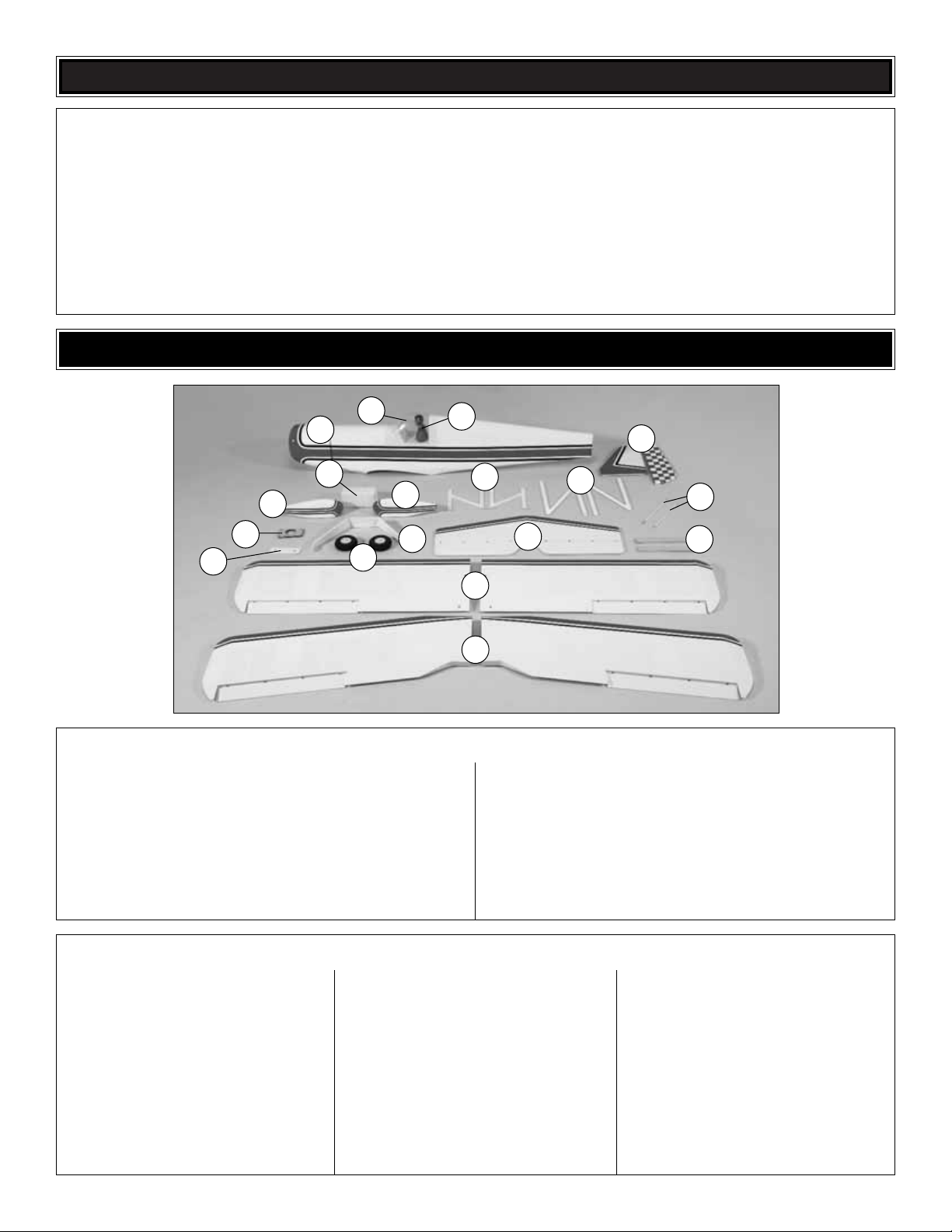
KIT CONTENTS
Before starting to build, take an inventory of this kit to make sure it is complete, and inspect the parts to make sure they
are of acceptable quality. If any parts are missing or are not of acceptable quality, or if you need assistance with assembly,
contact Product Support. When reporting defective or missing parts, use the part names exactly as they are written in
the Kit Contents list.
Great Planes Product Support
3002 N. Apollo Drive, Suite 1
Champaign, IL 61822
Telephone: (217) 398-8970, ext. 5
Fax: (217) 398-7721
E-mail: airsupport@greatplanes.com
1. Fuselage
2. Wheel Pants (L&R)
3. Fuel Tank
4. Cabanes (2)
5. “N”Struts (2)
6. Fin and Rudder
7. Aileron Joiner Rods (2)
8. Plywood Engine Mount Plate
9. Wing Bolt Plate
10. Main Landing Gear
11. Main Wheels (2)
12. Stabilizer and Elevators
13. Wing Joiners (2)
14. Bottom Wing Panels (L&R)
15. Top Wing Panels (L&R)
16. Canopy
17. Pilot
(1) Brass Threaded Coupler
(11) 4-40 Steel Clevis Threaded
(7) Solder Clevis
(2) 3/16" x 2" [4.8 x 51mm] Bolt-On Axle
(1) Screw-Lock Pushrod Connector
(11) 4-40 Hex Nut
(2) 5/16" [8mm] x 24 Lock Nut
(8) 4-40 Lock Nut
(4) White Nylon Control Horn
(4) Nylon 1/4-20 x 2" [51mm] Bolt
(1) Nylon Clevis
(1) Nylon FasLink
(7) Black Heavy-Duty Control Horn
(1) 24" [610mm] White Plastic Inner Pushrod Tube
(20) Silicone Clevis Retainer
(42) 4 x 1/2" [13mm] SMS
(4) 6-32 x 1/4" [6.4mm] Socket Head Bolt
(2) 4-40 x 1/8" [3.2mm] Set Screw
(8) #2 x 3/8" [9.5mm] Phillips Screw
(4) 8-32 x 3/4" [19mm] SHCS
(8) 4-40 x 3/8" [9.5mm] Round Head Phillips Screw
(16) 4-40 x 1/2" [13mm] SHCS
(8) 8-32 x 1-1/4" [32mm] SHCS
(4) 8-32 x 1" [25.4mm] SHCS
(1) 3/32" [2.4mm] Wheel Collar
(4) 3/16" [4.8mm] Wheel Collar
(1) 2-56 x 36" [914mm] Pushrod – Thread One End
(2) 2-56 x 4" [102mm] Pushrod – Threaded One End
(4) 4-40 x 12" [305mm] Pushrod – Threaded One End
(3) 4-40 x 36" [914mm] Pushrod – Threaded One End
(20) #4 Lock Washer
(34) #4 Flat Washer
(4) #2 Flat Washer
(20) #8 Lock Washer
(20) #8 Flat Washer
(1) Glow Fuel Tank Hardware Bag
(1) Gas Fuel Tank Hardware Bag
(1) Engine Mounts (L&R)
(1) Tailwheel Assembly
(2) 2 x 80mm Rubber Bands
(6) 20 x 120mm Hook & Loop Material
(8) Strut Braces
(1) Nylon Retainer (for Screw-Lock Pushrod Connector)
(4) Hardwood Cowl Mounting Blocks
Kit Contents (Not Photographed)
Kit Contents
1
3
5
6
2
2
4
10
11
17
16
15
14
13
12
7
9
8
❏ 1. If you have not done so already, remove the major
parts of the kit from the box (wings, fuselage, cowl, tail
parts, etc.) and inspect them for damage. Be sure to label
the ailerons in some way to remind you of which wing panel
they belong to.If any parts are damaged or missing, contact
Product Support at the address or telephone number listed
on page 7.
❏ 2. Remove the masking tape and separate the ailerons
from the wing, the elevators from the stab, and the rudder
from the fin. Use a covering iron with a covering sock on
high heat to tighten the model’s cov ering if necessary. Apply
pressure over sheeted areas to thoroughly bond the
covering to the wood.
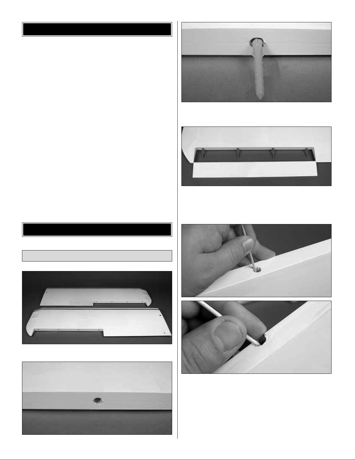
❏ ❏ 1. Locate the two bottom wing panels.
❏ ❏ 2. There are four holes drilled in each wing panel to
accept the hinges.Test fit each hinge in the wing.
❏ ❏ 3.Test fit the aileron to the wing.
❏ ❏ 4. Remove the hinges from the wing and aileron and
set them aside.
❏ ❏ 5. Mix up some 30-minute epoxy and Microballoons
(if using mixing cups, approximately 1/4 oz. [7g] of
Microballoons added to 1/4 oz. [7g] of mixed epoxy is
recommended). Use a toothpick to thoroughly apply the
mixture in the holes in the wing and aileron. Use the
toothpick to get the epoxy out of the outer edge of the
opening of the holes in the aileron so it doesn’t get into the
hinge pins.Wipe away any epoxy around the outside of the
holes with a paper towel.
Attach the Ailerons
WING ASSEMBLY
CHECK KIT CONTENTS
8
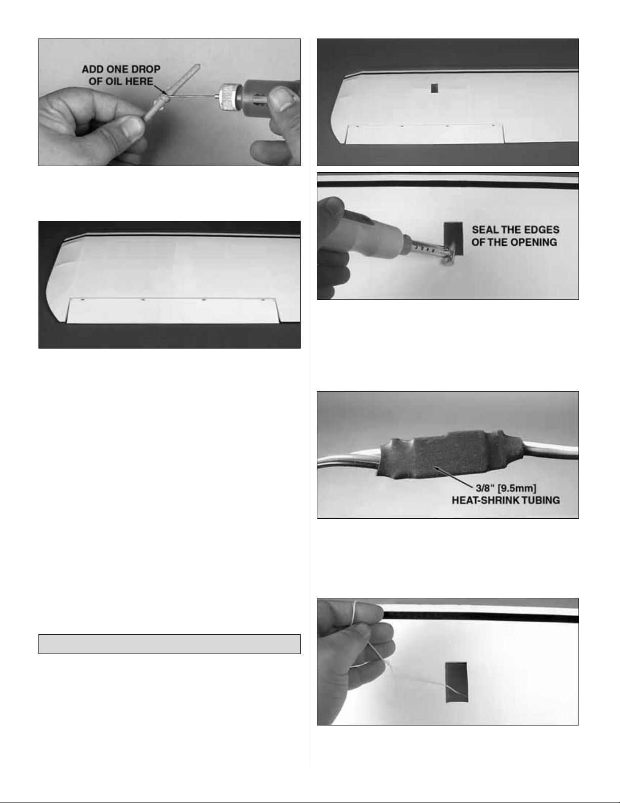
❏ ❏ 6.Before inserting the hinge in the hole, apply a drop of
oil to the hinge.This will serve to smooth the operation of the
hinge and also help prevent epoxy from binding the hinge.
❏ ❏ 7. Reattach the aileron. There should be a gap just
small enough to see through when the aileron is properly
attached as shown in the second photo.Caution: DO NOT
move the aileron until the epoxy has cured completely.
Doing so may work epoxy into the hinge and cause it to
bind! Use masking tape to hold the aileron in place until the
epoxy has completely cured.
❏ 8.Repeat steps 2-7 for the other top and bottom wing panels.
Note: There are two options for aileron installation on the
Giant Aeromaster ARF. One option is to use two bottom
aileron servos to drive all four ailerons.The second option is
to install an aileron servo for each of the four ailerons.You
will repeat the following steps f or the top wing if you choose
to use four aileron servos. If you choose to use the two
servo option, later in the manual after the wings are
mounted, you will join the two ailerons on each side.
❏ ❏ 1. Locate the aileron servo bay in the bottom of the
wing panel. Remove the covering from the opening using a
sharp hobby knife.Seal down the edges of the opening with
a sealing iron after cutting.
❏ ❏ 2. Attach a 36" [914mm] ser vo extension to the aileron
servo and seal the connection using 3/8" [9.5mm] heatshrink tubing as shown (not included).
❏ ❏ 3. Inside the cutout for the servo there is a length of
string taped to the interior of the wing. Carefully pull this
string up and out of the aileron servo bay.
Install the Ailerons Servos
9
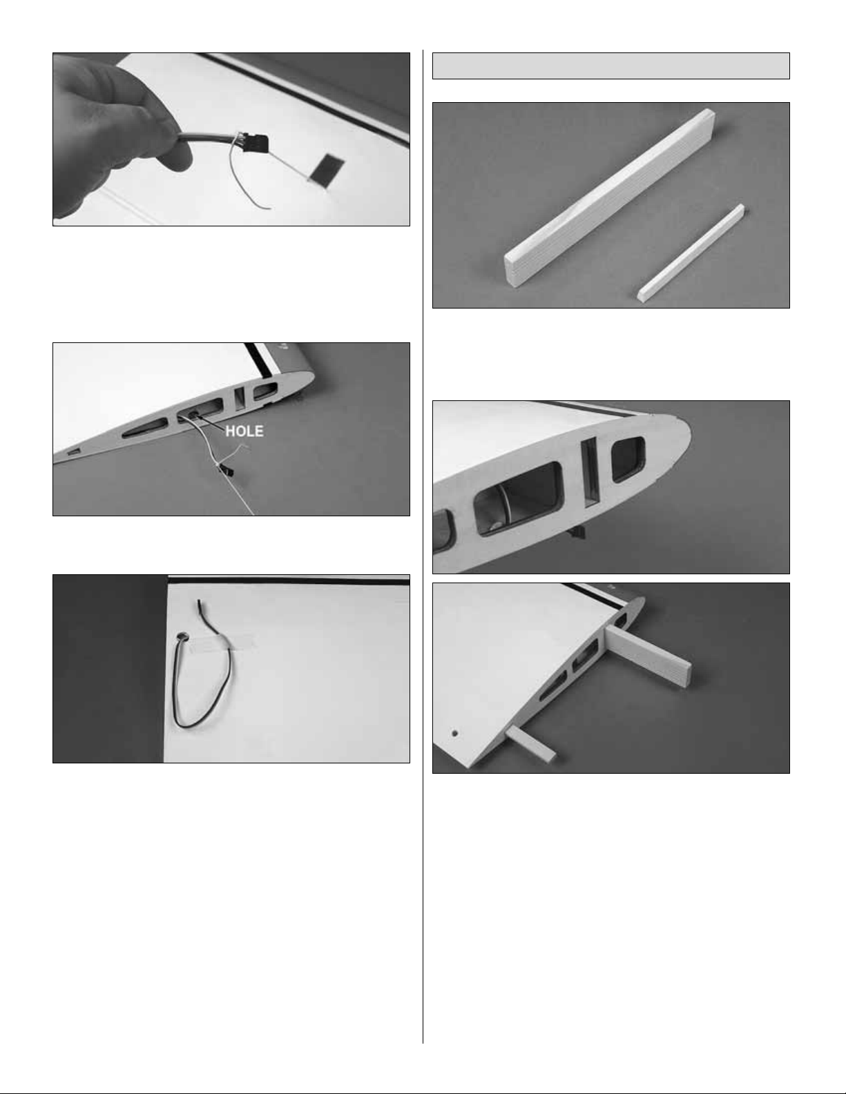
❏ ❏ 4. Securely attach the string to the end of the servo
lead.The other end of the string is attached with tape on the
inside of the wing near the root.Pull this end of the string up
and through the small 1/2" [13mm] hole in the top of the
wing panel.You will need to remove the covering from this
small hole using a sharp hobby knife.
❏ ❏ 5. Pull the string to route the servo lead through the
wing and out the small hole in the top of the wing.
❏ ❏ 6.Attach the servo lead to the wing panel with a small
piece of masking tape.
❏ ❏ 7. Mount the ser vo to the wing using the hardware
provided by your manufacturer. The output shaft spline will
face the LE of the wing.Remove the servo mounting screws
after installing the servo and harden the screw holes by
wicking some thin CA into them and allowing it to harden.
Then reinstall the servo mounting screws.
❏ 8. Repeat steps 1 to 7 for the other wing panel.
❏ 9. If using a four servo setup, you will repeat steps 1 to
7 above for the top wing. The 1/2" [13mm] holes for the
servo leads to exit the bottom of the top wing are located
further in from the center of the wing than as on the bottom
wing. Remove the covering from these holes only if using
the aileron servos in the top wing.
❏ 1. Locate the large wing joiners for the bottom wing.
These will be the large rectangular joiner and the larger of
the two small angled joiners.Measure and mark the centers
of the joiners.
❏ 2. Test fit the wing joiners into one wing panel. Sand the
wing joiners as needed for a good fit.
❏ 3. Slide the other wing panel onto the wing joiners. Sand
the wing joiners as needed for a good fit. The wing roots
should be flush with little or no gap present.
❏ 4. Separate the wing panels and remove the wing joiners.
❏ 5. Mix a large batch of 30-minute epoxy (if using mixing
cups, 1 oz. [28g] of mixed epoxy is a good amount.)
❏ 6.
Thoroughly
coat the inside of the wing joiner pockets
and wing roots with 30-minute epoxy.
❏ 7. Apply epoxy to each of the wing joiners and insert
them into the pockets in one wing panel.
Join the Bottom Wing
10
 Loading...