

Page 1
WARRANTY
Great Planes®Model Manufacturing Co.
guarantees this kit to be free from defects in both material and workmanship at the date of purchase. This
warranty does not cover any component parts damaged by use or modification. In no case shall Great Planes’ liability exceed the original cost of the
purchased kit. Further, Great Planes reserves the right to change or modify this warranty without notice.
In that Great Planes has no control over the final assembly or material used for final assembly, no liability shall be assumed nor accepted for any
damage resulting from the use by the user of the final user-assembled product. By the act of using the user-assembled product, the user accepts all
resulting liability.
If the buyer is not prepared to accept the liability associated with the use of this product, the buyer is advised to return this kit immediately in new and
unused condition to the place of purchase.
To make a warranty claim send the defective part or item to Hobby Services at the address below:
Hobby Services
3002 N. Apollo Dr., Suite 1
Champaign, IL 61822
USA
Include a letter stating your name, return shipping address, as much contact information as possible (daytime telephone number, fax number, e-mail
address), a detailed description of the problem and a photocopy of the purchase receipt.Upon receipt of the package the problem will be evaluated as
quickly as possible.
READ THROUGH THIS MANUAL BEFORE STAR TING
CONSTRUCTION. IT CONTAINS IMPORTANT
INSTRUCTIONS AND WARNINGS CONCERNING
THE ASSEMBLY AND USE OF THIS MODEL.
GPMZ0197 for GPMA1224 V1.0Entire Contents © Copyright 2005
Champaign, IL
(217) 398-8970, Ext. 5
airsupport@greatplanes.com
INSTRUCTION MANUAL
Wingspan: 80.5 in [2045mm]
Wing Area: 1518 sq in [97.9 dm2]
Weight: 13-15 lb [5900–6800g]
Wing Loading: 20–23 oz/sq ft [61–70 g/dm2]
Length: 54.5 in [1385mm]
Radio: 4 or 5-channel, 7 to 8 ser vos
Engine: 1.2–1.6 cu in [19.5–26.0cc] two-stroke,
1.2–1.8 cu in [19.5–29.5cc] four-stroke,
1.5–2.1 cu in [25–35cc] gas
™
Page 2
INTRODUCTION................................................................2
AMA ...................................................................................2
IMAA ..................................................................................3
SAFETY PRECAUTIONS..................................................3
DECISIONS YOU MUST MAKE ........................................3
Engine Recommendations...........................................3
Fuel Tank Setup...........................................................4
Spinner.........................................................................4
Building Stand..............................................................4
Flap & Aileron Setup....................................................4
Radio Equipment.........................................................4
ADDITIONAL ITEMS REQUIRED.....................................5
Hardware & Accessories .............................................5
Adhesives & Building Supplies....................................5
Optional Supplies & Tools............................................5
IMPORTANT BUILDING NOTES.......................................5
ORDERING REPLACEMENT PARTS ...............................6
METRIC CONVERSIONS..................................................6
KIT INSPECTION...............................................................7
PREPARATIONS................................................................8
ASSEMBLE THE WINGS ..................................................8
Mount the Servos.........................................................8
Hinge the Flaps & Ailerons..........................................9
Hook Up the Flaps & Ailerons .....................................9
Finish the Wings........................................................11
ASSEMBLE THE FUSELAGE.........................................12
Mount the Stab ..........................................................12
Mount the Fin .............................................................13
Mount the Landing Gear............................................15
Mount the Engine.......................................................16
Glow Engine........................................................16
Gas Engine (Fuji BT-32)......................................16
Install the Fuel Tank...................................................18
Hook up the Throttle & Nose Gear Steering..............19
Hook up the Elevator & Rudder Servos.....................20
GET THE MODEL READY TO FLY..................................20
Mount the Receiver & Battery....................................20
Center the Servos ......................................................21
Check the Control Directions.....................................21
Set the Control Throws..............................................22
Balance the Model (C.G.)..........................................22
Balance the Model Laterally......................................23
PREFLIGHT.....................................................................23
Identify Your Model.....................................................23
Charge the Batteries ..................................................23
Balance the Propellers...............................................23
Ground Check............................................................24
Range Check.............................................................24
ENGINE SAFETY PRECAUTIONS.................................24
AMA SAFETY CODE (excerpts)....................................24
IMAA SAFETY CODE (excerpts)...................................25
CHECK LIST ....................................................................26
FLYING.............................................................................27
Take Off......................................................................27
Flight..........................................................................28
Landing......................................................................28
ENGINE MOUNTING TEMPLATES.................................31
Thank you for purchasing the Great Planes Giant Big Stik
™
ARF. Due to the popularity of the “Stik” series of models, it
was only a matter of time before Great Planes released a
giant version. And this Stik, like all of its predecessors, is
simple and rugged.The Giant Big Stik ARF can be powered
by either a spark-ignition “gas” engine or a glow engine.
Refer to
“Engine Recommendations”
under the
“DECISIONS YOU MUST MAKE”
section of this manual for
information that may help you decide how to power your
Giant Big Stik ARF.
For the latest technical updates or manual corrections to the
Great Planes Giant Big Stik ARF visit the Great Planes web
site at
www.greatplanes.com
. Open the “Airplanes” link,
then select the Giant Big Stik ARF. If there is new technical
information or changes to this model, a “tech notice”box will
appear in the upper left corner of the page.
We urge you to join the AMA (Academy of Model
Aeronautics) and a local R/C club. The AMA is the
governing body of model aviation and membership is
required to fly at AMA clubs. Though joining the AMA
provides many benefits, one of the primary reasons to join
is liability protection. Coverage is not limited to flying at
contests or on the club field. It even applies to flying at
public demonstrations and air shows.Failure to comply with
the Safety Code (excerpts printed in the back of the
manual) may endanger insurance coverage. Additionally,
training programs and instructors are available at AMA club
sites to help you get started the right way. There are over
2,500 AMA chartered clubs across the countr y.Contact the
AMA at the address or toll-free phone number below.
IMPORTANT!!! Two of the most important things you can
do to preserve the radio controlled aircraft hobby are to
avoid flying near full-scale aircraft and avoid flying near or
over groups of people.
Academy of Model Aeronautics
5151 East Memorial Drive
Muncie, IN 47302-9252
Tele: (800) 435-9262
Fax (765) 741-0057
Or via the Internet at:
http://www.modelaircraft.org
AMA
INTRODUCTIONTABLE OF CONTENTS
2
Page 3

The Great Planes Giant Big Stik ARF is an excellent sportscale model and is eligible to fly in IMAA events.The IMAA
(International Miniature Aircraft Association) is an
organization that promotes non-competitive flying of giantscale models. If you plan to attend an IMAA event, obtain a
copy of the IMAA Safety Code by contacting the IMAA at
the address or telephone number below, or by logging on to
their web site.
IMAA
205 S. Hilldale Road
Salina, KS 67401
(913) 823-5569
www.fly-imaa.org/imaa/sanction.html.
1.Your Giant Big Stik ARF should not be considered a toy,
but rather a sophisticated, working model that functions
very much like a full-size airplane. Because of its
performance capabilities, the Giant Big Stik ARF, if not
assembled and operated correctly, could possibly cause
injury to yourself or spectators and damage to property.
2. You must assemble the model according to the
instructions. Do not alter or modify the model, as doing so
may result in an unsafe or unflyable model. In a few cases
the instructions may differ slightly from the photos.In those
instances the written instructions should be considered
as correct.
3.You must take time to build straight, true and strong.
4. You must use an R/C radio system that is in first-class
condition, and a correctly sized engine and components
(fuel tank, wheels, etc.) throughout the building process.
5.You must correctly install all R/C and other components
so that the model operates correctly on the ground and in
the air.
6.You must check the operation of the model before every
flight to insure that all equipment is operating and that the
model has remained structurally sound. Be sure to check
clevises or other connectors often and replace them if they
show any signs of wear or fatigue.
7. If you are not an experienced pilot or have not flown this
type of model before, we recommend that you get the
assistance of an experienced pilot in your R/C club for your
first flights. If you’re not a member of a club, your local
hobby shop has information about clubs in your area whose
membership includes experienced pilots.
8.While this kit has been flight tested to exceed normal use, if
the plane will be used for extremely high stress flying, such as
racing, or if an engine larger than one in the recommended
range is used, the modeler is responsible for taking steps to
reinforce the high stress points and/or substituting hardware
more suitable for the increased stress.
Remember:Take your time and follow the instructions to
end up with a well-built model that is straight and true.
This is a partial list of items required to finish the Giant Big
Stik ARF that may require planning or decision-making
before starting to build. Order numbers are provided
in parentheses.
The recommended engine size range for the Giant Big Stik
ARF is specified on the cover of this manual. All engines
within the specified range will power this model well.Never
fly the Giant Big Stik ARF with an engine larger than one in
the specified range because it has not been designed or
tested for larger engines. Powered by a two-stroke glow
engine such as the O.S.®MAX 1.60 FX, the Giant Big Stik
ARF performs like any .60-size sport plane with the added
stability and durability of any well-designed giant plane. If
flying the Giant Big Stik ARF with a spark-ignition gas
engine, the kit includes a plywood engine mount plate and
engine mount standoffs to facilitate the Fuji Engines
™
BT-32. If using another brand of gas engine, use the
instructions as a guide for how to mount yours.
If you haven’t yet built a model with a gas engine, but are
considering using one, two of the benefits are fuel economy
(not only is gasoline cheaper than glow fuel, but gas engines
typically burn less fuel as well) and considerably cleaner
exhaust residue. Most gas engines, however, are heavier
than glow engines and require premixing gas and oil.
Here are the order numbers for O .S.MAX and Fuji engines:
❏ O.S.1.60 FX ringed with muffler (OSMG0660)
❏ O.S.1.60 FX ringed without muffler (OSMG0661)
Engine Recommendations
DECISIONS YOU MUST MAKE
We, as the kit manufacturer, provide you with a top
quality, thoroughly tested kit and instructions, but
ultimately the quality and flyability of your finished model
depends on how you build it;therefore, we cannot in any
way guarantee the performance of your completed
model, and no representations are expressed or implied
as to the performance or safety of your completed model.
PRO TECT YOUR MODEL,YOURSELF
& OTHERS...FOLLOW THESE
IMPORTANT SAFETY PRECAUTIONS
IMAA
3
Page 4
❏ #5010 muffler for O.S. 1.60 FX engine (OSMG2846)
❏ Fuji BT-32S R/C gas engine (FJIG0033)
Per the IMAA Safety Code, magneto spark-ignition engines
must have a coil-grounding switch on the aircraft to stop the
engine and prevent accidental starting.The switch must be
operated manually (without the use of the transmitter) and
be accessible by the pilot and assistant. For use with the
Fuji engine shown, the manually operated switch w as made
from a .3 amp slide switch, 16-gauge wire and a covered,
crimp-on connector purchased at the local Radio Shack®.
Slightly different hardware may be required if using a
different spark-ignition engine. All of the components
required are available at any hardware or homeimprovement store.
If using the Fuji BT-32SB engine the following hardware
must be purchased separately:
❏ (4) 1/4-20 x 2-1/4" or 1/4-20 x 2-1/2" Phillips-head bolts
❏ (4) 1/4-20 blind nuts
❏ (4) 1/4" flat washers
❏ (4) 1/4" lock washers
❏ (4) 10-32 x 3/4" socket-head cap screws
❏ (4) #10 lock washers
Note: If using the Fuji BT-32 (or most other gas engines),
the nose-gear option may not be used and the model must
be built as a taildragger. This is because of the extended
distance from the firewall that the engine would have to be
mounted in order to clear the nose gear hardware.
The fuel tank included with this kit is suitable for use with
glow fuel.However, if using a gas engine, the fuel tank must
be converted to work with gasoline. This can be done by
purchasing a Sullivan #484 Gasoline/Diesel fuel tank
conversion kit (SULQ2684), a package of Du-Bro #813 1/8"
[3.2mm] I.D. fuel line barbs (DUBQ0670) and 3' of Great
Planes gasoline fuel tubing (GPMQ4135). Without the fuel
line barbs some types of gas-compatible fuel line may slip
off the metal fuel tubes. If the Sullivan conversion kit is not
available the Du-Bro #400 gas conversion stopper
(DUBQ0675) and one 12" [300mm] piece of K+S 1/8"
[3.2mm] soft brass tubing (K+SR5128, box of 5) could also
be used to make the conversion.Full instructions on how to
set up the fuel tank and make the conversion to gas are
provided in this manual.
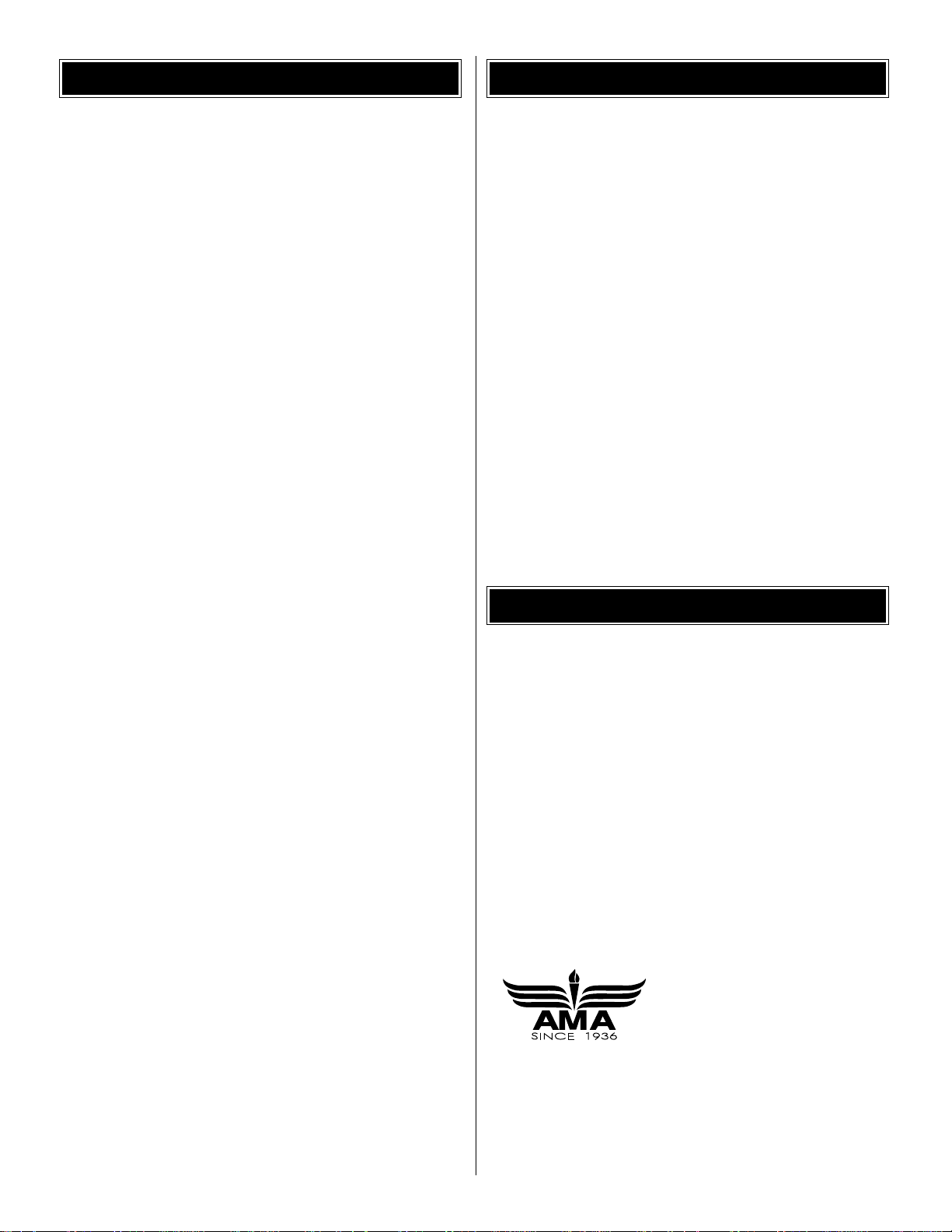
The model on the kit box cover is shown with a Great Planes
2-3/4" [70mm] aluminum spinner (GPMQ4555) (not included).
An adapter nut for mounting the spinner cone is also required.
(Order No. OSMG4588 for use with the O.S. 1.60 FX.) The
Great Planes spinner is intended to be used on engines that
have a threaded crankshaft–not engines that use a propeller
bolt (such as most gas engines). In this case, a different type
of spinner will have to be used. In most cases the propeller
cutouts in the cone will also have to be enlarged.A rotary tool
with a carbide cutter works great for the rough work, followed
by a small metal file to clean up the edges. Always wear eye
protection when working with power tools.
A building stand or cradle comes in handy.We use the Robart
Super Stand II (ROBP1402) for all of our projects in R&D.
The Giant Big Stik ARF is intended to be flown with flaps using
a radio with a minimum of five channels.If, however, you have
only a four-channel radio, the Giant Big Stik ARF could be
flown without flaps.In this case, the flap servos will hav e to be
linked to the aileron servos using Y-connectors. Then, all four
control surfaces on the wings will function as ailerons.
Since the Giant Big Stik ARF is a large model, standard
servos should not be used to operate the control surfaces.
Servos with a minimum torque rating of 50 oz-in are
Radio Equipment
Flap & Aileron Setup
Building Stand
Spinner
Fuel T ank Setup
4
Page 5
suitable for the flaps and ailerons.The elevator and rudder
should each be operated by a servo with approximately 70
oz-in torque.The throttle and nose wheel may be operated
by standard servos.
The following servo extensions and Y-harnesses were
also used to build the Giant Big Stik ARF as shown in
the manual.
❏ (2) 36" [910mm] servo extensions for elevator and
rudder (HCAM2726 for Futaba)
❏ (2) 24" [610mm] servo extensions for ailerons
(HCAM2721 for Futaba)
❏ (2) 6" [150mm] servo extensions for flaps (HCAM2701
for Futaba)
❏ (2) Futaba AEC-13 Y-connectors for flap and aileron
servos (FUTM4130)
A battery pack with a minimum of 1,000mAh should also
be used. When flying giant-scale models such as this,
ALWAYS check the battery condition before each flight.
In addition to the items listed in the
“Decisions Y ou Must
Make”
section, following is the list of hardware and
accessories required to finish the Giant Big Stik ARF. Order
numbers are provided in parentheses.
❏ Propeller and spare propellers suitable for your engine
❏ R/C foam rubber (1/4" [6mm] – HCAQ1000, or 1/2"
[13mm] – HCAQ1050)
❏ 3' [900mm] standard silicone fuel tubing (GPMQ4131)
-or-
❏ 3' [900mm] gasoline fuel tubing (GPMQ4135)
❏ Stick-on segmented lead weights (GPMQ4485)
In addition to common household tools and hobby tools, this
is the “short list” of the most important items required to
build the Giant Big Stik ARF.
Great Planes Pro™CA and
Epoxy glue are recommended.
❏ 1/2 oz. [15g] Thin Pro CA (GPMR6001)
❏ 1/2 oz. [15g] Medium Pro CA+ (GPMR6007)
❏ Pro 30-minute epoxy (GPMR6047)
❏ Denatured alcohol (for epoxy clean up)
❏ CA applicator tips (HCAR3780)
❏ Threadlocker
™
thread-locking cement (GPMR6060)
❏ Drill bits: 1/16" [1.6mm], 3/32" [2.4mm], 1/8" [3.2mm],
3/16" [4.8mm], 13/64" [5.2mm] (or 3/16"), 15/64 [6mm]
(or 1/4"), 1/4" [6.4mm], 9/32" [7.1mm]
❏ 8-32 tap and drill set (GPMR8103)
-or-
❏ 8-32 Tap and #29 drill
❏ Tap handle (GPMR8120)
❏ Small metal file
❏ Silver solder w/flux (GPMR8070)
❏ #1 Hobby knife (HCAR0105)
❏ #11 Blades (5-pack, HCAR0211)
❏ 21st Century
®
sealing iron (COVR2700)
❏ 21st Century iron cover (COVR2702)
Here is a list of optional tools mentioned in the manual that
will help you build the Giant Big Stik ARF.
❏ Pro 6-minute epoxy (GPMR6045)
❏ 2 oz. [57g] spray CA activator (GPMR6035)
❏ 4 oz. [113g] aerosol CA activator (GPMR634)
❏ CA debonder (GPMR6039)
❏ 3M 75 Repositionable spray adhesive (MMMR1900)
❏ Epoxy brushes (6, GPMR8060)
❏ Mixing sticks (50, GPMR8055)
❏ Mixing cups (GPMR8056)
❏ Builder’s Triangle Set (HCAR0480)
❏ 36" Metal ruler (HCAR0475)
❏ Large T-pins (100, HCAR5200)
❏ Robart Super Stand II (ROBP1402)
❏ Switch & Charge Jack Mounting Set (GPMM1000)
❏ Rotary tool such as Dremel
®
❏ Rotary tool reinforced cut-off wheel (GPMR8200)
❏ Hobby Heat
™
Micro Torch II (HCAR0755)
❏ Dead Center
™
Engine Mount Hole Locator (GPMR8130)
❏ AccuThrow
™
Deflection Gauge (GPMR2405)
❏ CG Machine
™
(GPMR2400)
❏ Precision Magnetic Prop Balancer
™
(TOPQ5700)
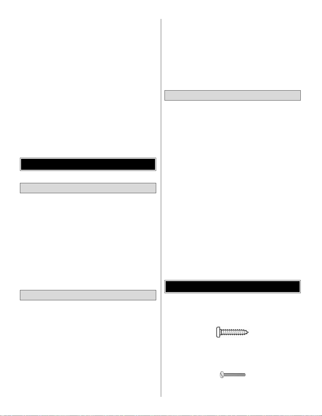
• Sheet metal screws are designated by a number and a
length. For example, #6 x 3/4" [19mm].
This is a number six screw that is 3/4" [19mm] long.
• Machine screws are designated by a number, threads
per inch, and a length. For example, 4-40 x 3/4" [19mm].
This is a number four screw that is 3/4" [19mm] long
with forty threads per inch.
IMPORTANT BUILDING NOTES
Optional Supplies & Tools
Adhesives & Building Supplies
Hardware & Accessories
ADDITIONAL ITEMS REQUIRED
5
Page 6
• When you see the term
test fit
in the instructions, it
means that you should first position the part on the
assembly without using any glue, then slightly modify
or custom fit the part as necessar y for the best fit.
• Whenever the term
glue
is written you should rely upon
your experience to decide what type of glue to use.When
a specific type of adhesive works best for that step, the
instructions will make a recommendation.
• Whenever just
epoxy
is specified you may use either
30-minute (or 45-minute) epoxy or 6-minute epoxy.When
30-minute epoxy is specified it is highly recommended
that you use only 30-minute (or 45-minute) epoxy,
because you will need the working time and/or the
additional strength.
•
Photos
and
sketches
are placed before the step they
refer to. Frequently you can study photos in following
steps to get another view of the same parts.
• Following are the MonoKote®colors used on the Giant
Big Stik ARF in case patches or repairs are ever needed:
True Red – TOPQ0227
Black – TOPQ0208
White – TOPQ0204
• The stabilizer and wing incidences and engine thrust
angles have been factory-built into this model. However,
some technically-minded modelers may wish to check
these measurements anyway. To view this information
visit the web site at
www.greatplanes.com
and click on
“Technical Data.” Due to manufacturing tolerances which
will have little or no effect on the way your model will fly,
please expect slight deviations between your model and
the published values.
Replacement parts for the Great Planes Giant Big Stik ARF
are available using the order numbers in the Replacement
Parts List that follows.The fastest, most economical service
can be provided by your hobby dealer or mail-order company.
To locate a hobby dealer, visit the Hobbico®web site at
www.hob bico .com
.Choose “Where to Buy”at the bottom of the
menu on the left side of the page. Follow the instructions
provided on the page to locate a U.S ., Canadian or International
dealer.If a hobby shop is not available, replacement parts may
also be ordered from Tower Hobbies®at
www.to werhob bies.com
,
or by calling toll free (800) 637-6050.
Parts may also be ordered directly from Hobby Services by
calling (217) 398-0007, or via facsimile at (217) 398-7721,
but full retail prices and shipping and handling charges will
apply. Illinois and Nevada residents will also be charged
sales tax.If ordering via fax, include a Visa®or MasterCard
®
number and expiration date for payment.
Mail parts orders and payments by personal check to:
Hobby Services
3002 N. Apollo Dr ive, Suite 1
Champaign, IL 61822
Be certain to specify the order number exactly as listed in
the Replacement Parts List. Payment by credit card or
personal check only; no C.O.D.
If additional assistance is required for any reason contact
Product Support by e-mail at
productsupport@greatplanes.com
,
or by telephone at (217) 398-8970.
REPLACEMENT PARTS LIST
Order Number Description How to Purchase
Missing pieces..........Contact Product Support
Instruction manual ....Contact Product Support
Full-size plans ............................Not Available
GPMA2815 ..........Wing Set ....................Contact Hobby Supplier
GPMA2816 ..........Fuselage ....................Contact Hobby Supplier
GPMA2817 ..........Tail Surface Kit ..........Contact Hobby Supplier
GPMA2818 ..........Main Gear ..................Contact Hobby Supplier
GPMA2819 ..........Nose Gear..................Contact Hobby Supplier
GPMA2820 ..........Wing Tube ..................Contact Hobby Supplier
1" = 25.4mm (conversion factor)
METRIC CONVERSIONS
ORDERING REPLACEMENT PARTS
6
1/64" = .4 mm
1/32" = .8 mm
1/16" = 1.6 mm
3/32" = 2.4 mm
1/8" = 3.2 mm
5/32" = 4.0 mm
3/16" = 4.8 mm
1/4" = 6.4 mm
3/8" = 9.5 mm
1/2" = 12.7 mm
5/8" = 15.9 mm
3/4" = 19.0 mm
1" = 25.4 mm
2" = 50.8 mm
3" = 76.2 mm
6" = 152.4 mm
12" = 304.8 mm
18" = 457.2 mm
21" = 533.4 mm
24" = 609.6 mm
30" = 762.0 mm
36" = 914.4 mm
Page 7
7
KIT INSPECTION
Before starting to build, use the Kit Contents list to take an inventory of this kit to make sure it is complete and inspect the parts
to make sure they are of acceptable quality. If any parts are missing or are not of acceptable quality, or if you need assistance
with assembly, contact Great Planes Product Support. When reporting defective or missing parts, use the part names exactly
as they are written in the Kit Contents list on this page.
Great Planes Product Support:
3002 N. Apollo Drive, Suite 1
Champaign, IL 61822
Telephone: (217) 398-8970, ext. 5
Fax: (217) 398-7721
E-mail:
airsupport@greatplanes.com
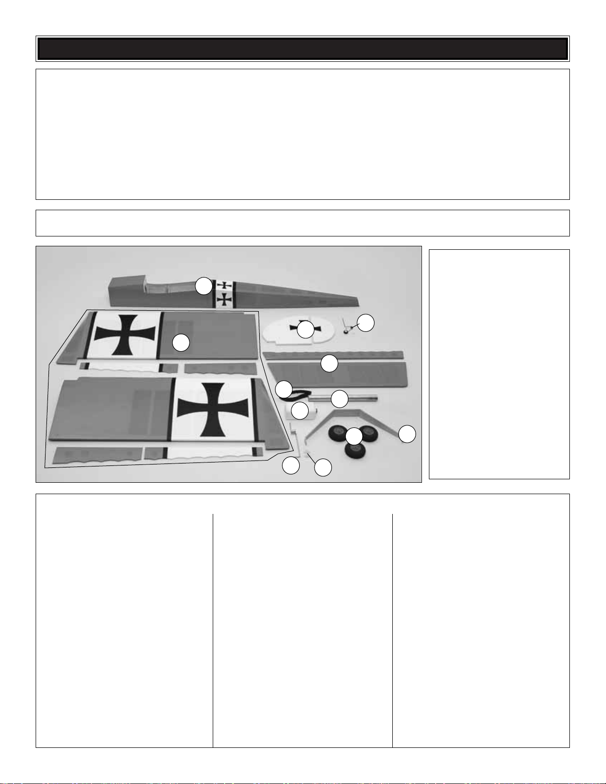
Parts Layout
Kit Contents
1. Fuselage
2. Wings, Flaps & Ailerons
3. Fin & Rudder
4. Stabilizer & Elevator
5. Tail Gear Assembly
6. 13-3/4" [350mm] Velcro Strip
7. Fuel Tank
8. Wing Joiner Tube
9. Nose Gear Wire
10. Nose Gear Bearing
11. Main Landing Gear
12. Wheels (3)
Wood Parts:
(2) Plywood Fuel Tank Former Set
(2) Plywood Fuji Engine Mount Plates
(1) Plywood Receiver/Battery Tray
(1) 1/4" x 1/4" x 8" [6.3 x 6.3 x 200mm]
Hardwood Stick
(1) 1/16" x 1" x 8" [1.6 x 25 x 200mm] Sheeting
(2) 3/8" x 2" [9.5 x 50mm] Hardwood Dowels
(1) 1/4" x 1-3/16" [6.3 x 30mm] Hardwood Dowel
Hardware:
(1) Nylon Tail Gear Eyelet
(4) Fuji Gas Engine Mounting Standoffs
(1) 1.20 – 1.60 Engine Mount, Right
(1) 1.20 – 1.60 Engine Mount, Left
(2) 2-56 x 36" [914mm] Pushrods
(6) 4-40 x 12" [305mm] Pushrods
(1) 36" [914mm] White Pushrod Tube
(for gas engine)
(1) 3/16" x 36" [4.8 x 914mm] Pushrod
Guide T ube
(6) Giant Control Horns
(6) Giant Control Horn Mounting Plates
(2) CA Hinge Strips
(6) Heat-Shrink T ubing
(1) Steering Arm
Nuts, Bolts, Connectors:
(2) 1/4-20 Blind Nuts (factory-installed
in fuselage)
(2) 1/4-20 x 2" [51mm] Nylon Wing Bolts
(12) 6-32 Blind Nuts (8 factory-installed)
(4) 6-32 x 1" [25mm] Screws
(8) #6 Flat Washers
(8) #6 Lock Washers
(2) 3/16" x 2" [4.8 x 50mm] Bolt-on Axles
(2) 5/16" Lock Nuts (for axles)
(2) 3/16" [4.8mm] Wheel Collars
(2) 6-32 Set Screws (for wheel collars)
(4) 6-32 x 3/4" [19mm] Phillips Screws
(1) 6-32 x 1/4" [6mm] Socket-Head Cap Screw
(4) 8-32 x 1-1/4" [32mm] Socket-Head Cap
Screws (engine mount)
(4) 8-32 x 1" [25mm] Socket-Head Cap
Screws (engine)
(4) 8-32 Blind Nuts
(4) #8 Flat Washers
(8) #8 Lock Washers
(2) Brass Screw-Lock Pushrod Connectors
(2) Nylon Retainers (for screw-lock
pushrod connectors)
(2) 4-40 x 1/8" [3.2mm] Socket-Head
Cap Screws
(2) Nylon Clevises
(2) 2-56 x 1" [25mm] Threaded Rod (gas)
(1) Nylon Ball Link (gas)
(1) 2-56 Ball Link Ball (gas)
(1) 2-56 Lock Nut (gas)
(6) 4-40 Clevises
(6) Large Solder Clevises
(6) 4-40 Nuts
(24) 4-40 x 3/4" [19mm] Phillips Screws
(control horns)
(14) Silicone Clevis Retainers
(8) #2 x 3/8" [9.5mm] Phillips Screws (4-fuel
tank hatch cover, 4-battery/receiver tray)
(8) #2 Washers
(1) 3/32" [2.4mm] Wheel Collar (tail gear)
(1) 4-40 Set Screw
Kit Contents (Not Photographed)
1
12
8
3
4
6
5
7
9
11
10
2
Page 8
Use a covering iron with a covering sock to remove any
wrinkles in the covering. Over sheeted areas, first glide the
iron over the wrinkle until it disappears, then come back
pressing hard on the iron to thoroughly bond the covering to
the wood. Hint: Use a small T-pin to poke several holes in
the covering over the lightening holes on the bottom of the
control surfaces. This will allow expanding air to escape
during the heating and tightening process.
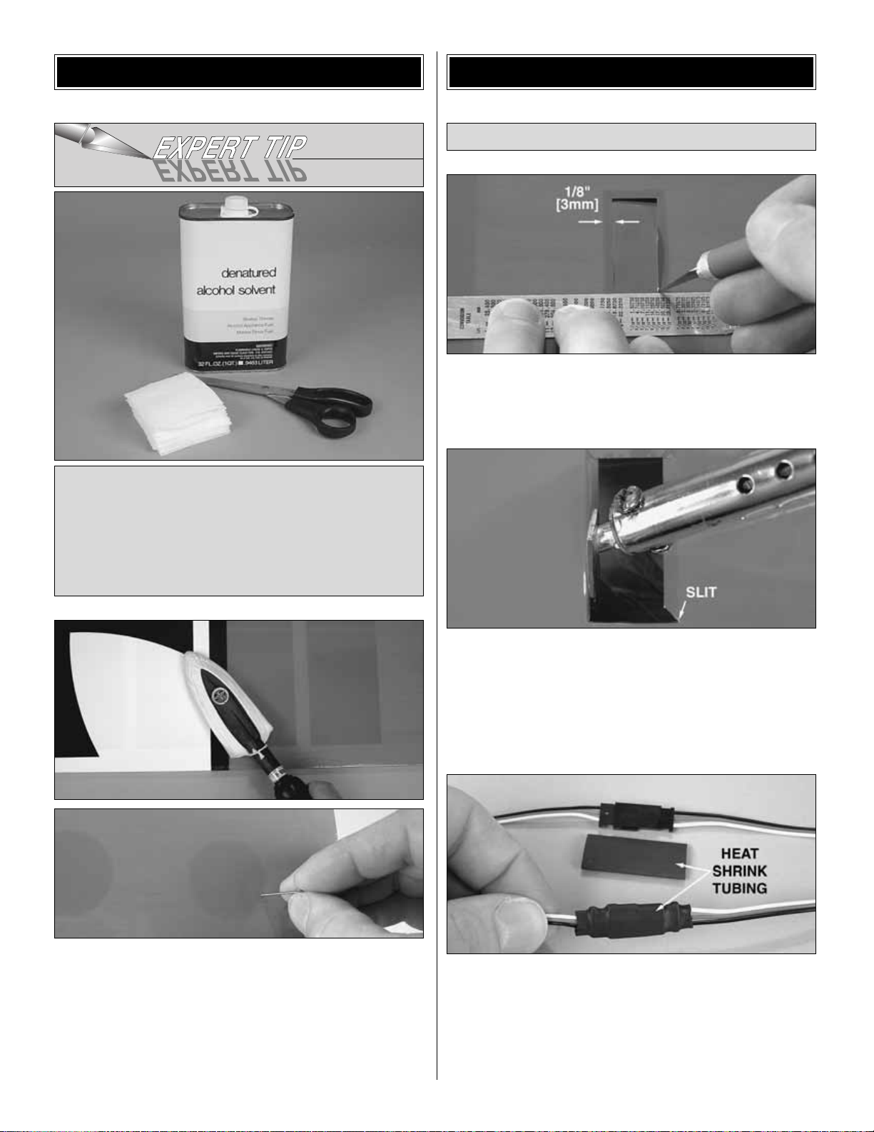
❏ 1. Use a straightedge and a hobby knife to cut the
covering 1/8" [3mm] inside the openings in the bottom of
both wings for the flap and aileron servos.
❏ 2. Slit the covering up to the corners of the openings,
then use a trim iron to iron the covering down inside.
❏ 3. Cut the covering from the bottom of the wing over the
holes for the servo wires next to the root end of both wings.
❏ 4. Connect one 12" [300mm] servo extension wire to
each aileron servo and connect one 6" [150mm] extension
wire to each flap servo.Cut two pieces of the included blac k
heat shrink tubing in half, making four 1-1/2" [40mm] pieces.
Center the pieces of tubing over the connections between
the servo wires and the extensions. Use a heat gun to
shrink the tubing, making the connections secure.
Mount the Servos
ASSEMBLE THE WINGS
During construction there will be several occasions where
epoxy cleanup will be necessary. Instead of wasting
whole paper towels, stack three or four paper towels on
top of each other and cut them into small squares. This
will conserve paper towels and the little squares are
easier to use. For epoxy clean up dampen the squares
with denatured alcohol.
PREPARATIONS
8
Page 9
❏ 5.Use the strings in the wings to pull the servo wires out
while placing the servos into the openings.With the servos
in position, drill 1/16" [1.6mm] holes into the wing for all the
servo mounting screws.Temporarily mount the servos with
the servo mounting screws that came with your servos.
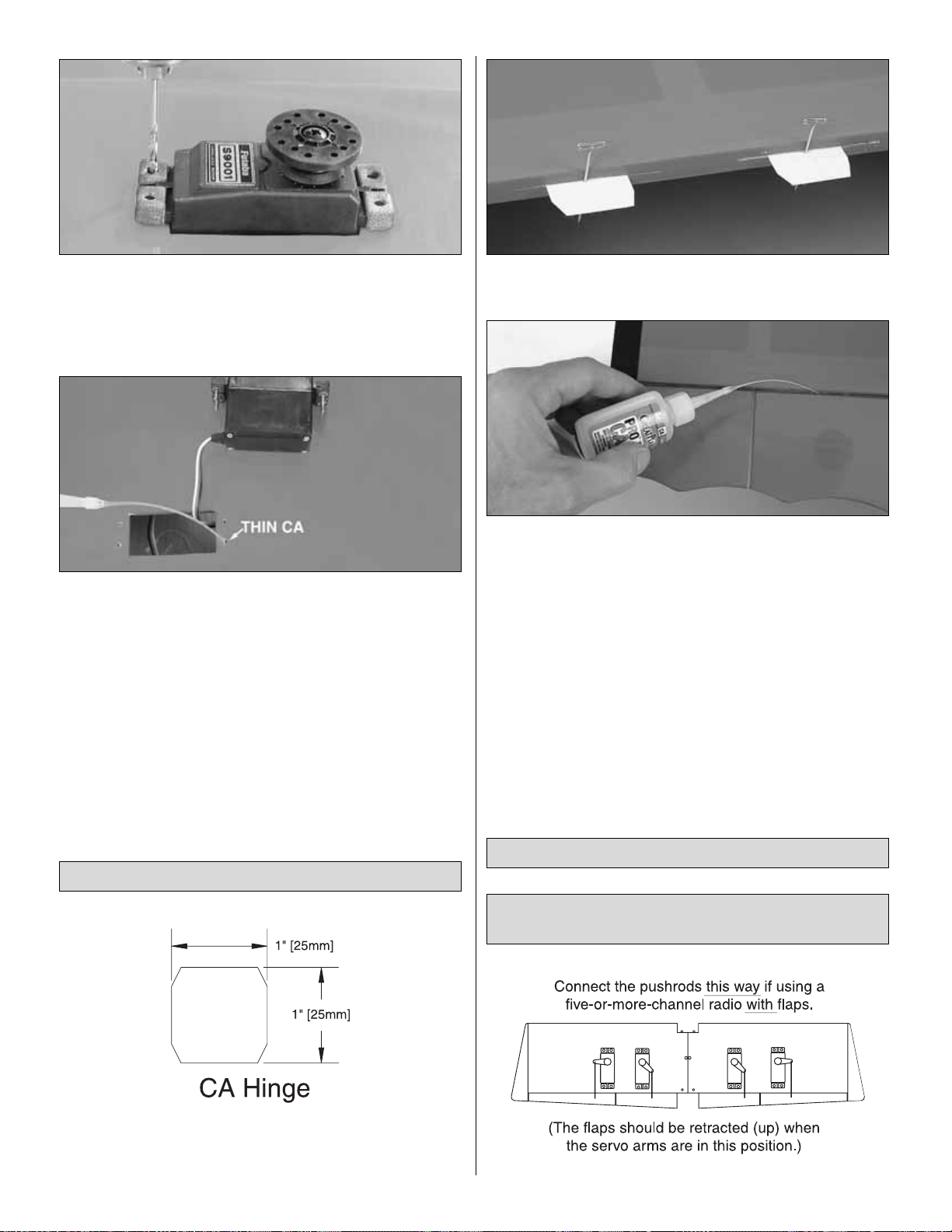
❏ 6.Remove the servo mounting screws and take the servos
out of the openings.Add a few drops of thin CA to each screw
hole to harden the “threads.” After the CA has hardened
reinstall all the screws to securely mount the servos.
❏ 1. Cut twelve 1" x 1" [25 x 25mm] CA hinges from the 2"
x 9" [50 x 230mm] CA hinge strip.Cut the corners off so the
hinges go in easier.
❏ 2.Stick a T-pin through the middle of all the hinges.Insert
six hinges into the hinge slots of both wings.
❏ 3. Join the flaps and ailerons to the wings with the hinges.
Make sure there is a small gap between the leading edge of
the flaps and ailerons and the trailing edge of the wings–just
enough to see light through or to slip a piece of paper through.
Take out the T-pins, then apply at least eight drops of thin CA
to both sides of all the hinges on both wings. Allow enough
time between each drop of CA so the hinge can absorb it
instead of running into the hinge gap. CA applicator tips are
highly recommended here so the amount and location of the
CA can be controlled.
❏ 4.After the CA has hardened for a f e w min utes, pull hard
on the flaps and ailerons to make sure they are secure.Add
more CA to any hinges that aren’t securely glued.
If you’re building your Giant Big Stik ARF with flaps
hook up the servos this way.
Hook Up the Flaps & Ailerons
Hinge the Flaps & Ailerons
9
Page 10
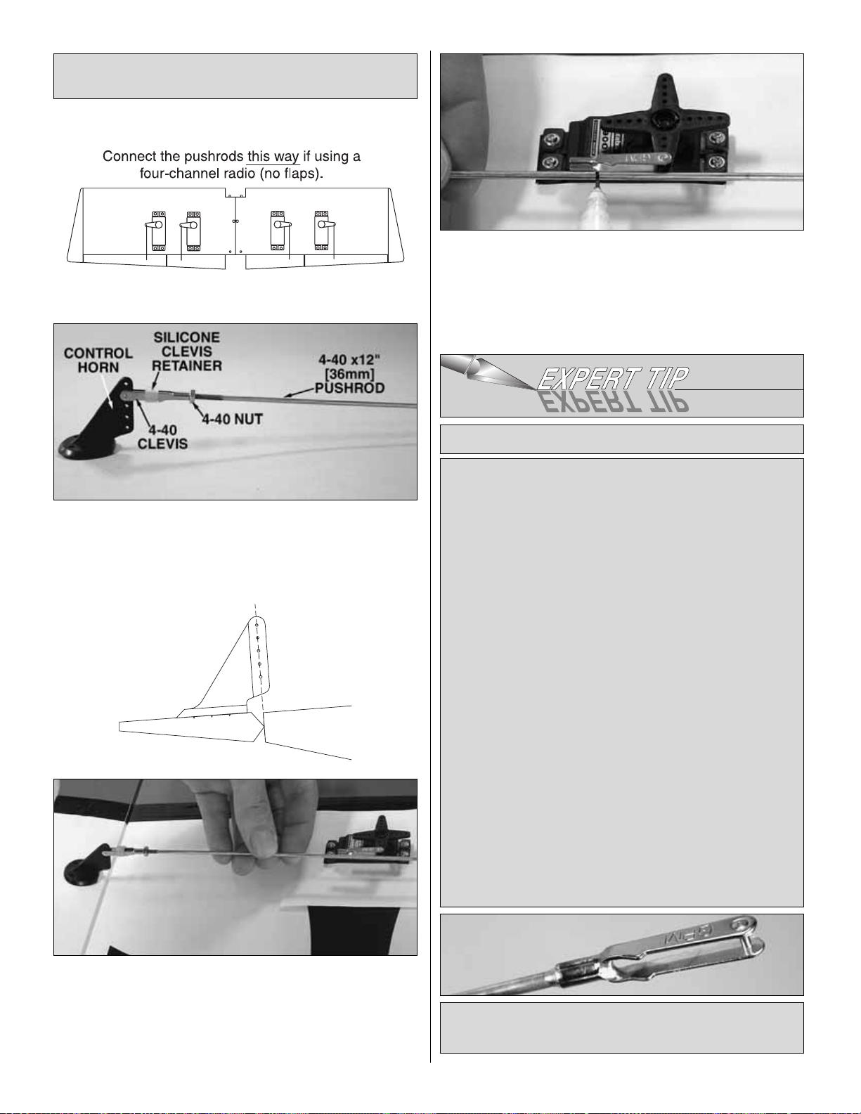
❏ 1. Make four pushrod assemblies from the hardware
shown in the photo. Turn the pushrods into the clevis
approximately twenty full turns.
❏ 2. Connect a solder-on clevis into the outer hole of one
of the aileron servo arms. (Do not cut off the unused servo
arms until instructed to do so when setting up the radio
later.) Hold one of the control horn/pushrod assemblies to
the wing with the horn resting on the aileron (as shown in
the sketch) and the pushrod up to the clevis.
❏ 3.Use a fine-point felt-tip pen to mark the pushrod where
it should be cut for soldering onto the clevis.
❏ 4. Cut the pushrod at the mark. Take the clevis off the
horn, then refer to the
“Expert Tip”
that follows about
soldering and solder the clevis onto the end of the pushrod.
This is what a properly soldered clevis looks like–shiny
solder with good flow, no blobs, flux removed.
1. Use denatured alcohol or other solvent to thoroughly
clean the pushrod. Roughen the end of the pushrod with
coarse sandpaper where it is to be soldered.
2. Apply a few drops of soldering flux to the end of the
pushrod, then use a soldering iron or a torch to heat it.
“Tin” the heated area with silver solder (GPMR8070) by
applying the solder to the end. The heat of the pushrod
should melt the solder–not the flame of the torch or
soldering iron–thus allowing the solder to flow .The end of
the wire should be coated with solder all the way around.
3.Place the clevis on the end of the pushrod.Add another
drop of flux, then heat and add solder. The same as
before, the heat of the parts being soldered should melt
the solder, thus allowing it to flow. Allow the joint to
naturally cool without disturbing. Avoid excess blobs, but
make certain the joint is thoroughly soldered. The solder
should be shiny, not rough. If necessary, reheat the joint
and allow to cool.
4. Immediately after the solder has solidified, but while it
is still hot, use a cloth to quickly wipe off the flux before it
hardens. Important: After the joint cools, coat with oil to
prevent rust. Note: Do not use the acid flux that comes
with silver solder for electrical soldering.
HOW T O SOLDER
If you’re
not
building your Giant Big Stik ARF with
flaps hook up the servos this way.
10
Page 11

❏ 5. Reconnect the pushrod to the ser vo horn, then mark
and drill 1/8" [3.2mm] holes through the aileron for the
control horn mounting screws.Mount the horn to the aileron
with four 4-40 x 3/4" [19mm] screws and the mounting plate
on the top.
❏ 6.Make the other aileron pushrod the same length as the
first, then hook up the other aileron with another control
horn and mounting screws.
❏ 7. If you’re building your model
without
flaps, make two
more pushrods the same way and connect the “flap” servos
to the “inner ailerons.”Then proceed to
“Finish the Wings.”
If you
are
building flaps, follow steps 8 through 10.
Now onto the flaps…
❏ 8. Place a servo arm on one of the flap ser vos. Rotate
the arm downward 30-degrees.
❏ 9.Make the flap pushrod and connect the flap to the flap
servo the same way you did the ailerons.
❏ 10. Hook up the other flap the same way.
❏ 1. Round one end of the 1/4" x 1-3/16" [6.4 x 30mm]
hardwood anti-rotation dowel.Use 30-minute epoxy to glue
the dowel into the end of one of the wings. Glue both 3/8" x
2" [9.5 x 50mm] hardwood wing dowels into the front of both
wings. 3/8" [10mm] of the wing dowels should protrude.
❏ 2.Cut the covering from the wing bolt holes in the wings and
from the holes in both 1/16" [1.6mm] plywood wing bolt
plates. Place the wing bolt plates on the wings using the
1/4-20 x 2" [50mm] nylon wing bolts to hold them in place.Mark
the outline of the wing bolt plates onto the wings using a
ballpoint pen.Remove the wing bolt plates and cut the covering
from the wings 1/8" [3mm] inside the lines you marked.
❏ 3. Glue the wing bolt plates into position using the wing
bolts to keep them in alignment.
Finish the Wings
11
Page 12

There are a few preparation and alignment procedures
that must be done before the stabilizer can be glued
into the fuselage...
❏ 1. Cut the covering from the slots in the fuselage for the
horizontal stabilizer (“stab”) and vertical stabilizer (“fin”).
Remove the balsa stick temporarily glued in place for
shipping. The same as was done for the servo openings in
the wings, cut and iron down the covering around the
elevator and rudder servo openings in the fuselage.
❏ 2. Taking accurate measurements, use a fine-point felt-
tip pen to mark the middle of the stabilizer near the trailing
edge. Use a builder’s square to extend the line mar king a
short centerline.
❏ 3. With the fuselage upside-down, slide the stabilizer all
the way into the slot with the centerline on the bottom. Use
the centerline to center the stab in the fuselage, then stick
a T-pin through the bottom of the fuselage into the stab to
hold the trailing edge in place.
❏ 4. Stick another T-pin into the bottom of the fuselage
centered over the firewall. Tie a loop in an approximately
70" [180cm] piece of non-elastic string. Slip the loop in the
string over this T-pin.
❏ 5. Fold a piece of masking tape over the string near the
other end and draw an arrow on it.Slide the tape along the
string and align the arrow with one end of the stab as
shown. Swing the string over to the same position on the
other end of the stab. Rotate the stab about the T-pin and
slide the tape along the string until the stab is centered and
the arrow aligns with both ends.
❏ 6. Use a fine-point felt-tip pen such as a Top Flite
®
Panel
Line Pen (TOPQ2510) to mar k the outline of the fuselage
on the top and bottom of the stab.
One more alignment procedure…
❏ 7. Carefully turn the fuselage back over (so it is upright)
and fit the wings together with the wing tube.Bolt the wing to
the fuselage with two 1/4-20 x 2" [50mm] nylon wing bolts.
Mount the Stab
ASSEMBLE THE FUSELAGE
12
Page 13

❏ 8. Stand approximately ten feet behind the model and see
if the stab aligns horizontally with the wing. If they align, go to
the next step.If the stab and wing do not align, first try placing
a few ounces of weight on the high side of the stab. If that
doesn’t do it, remove the stab from the fuselage and lightly
sand the slots in the fuselage to get the stab to align with the
wing. Reinser t the stab and check the alignment. Continue to
make small adjustments until alignment is achieved.
❏ 9. Remove the stab from the fuselage.Use a sharp #11
hobby knife or follow the
“Expert Tip”
below to cut the
covering from the stab along the lines.Use care to cut only
into the covering and not into the wood. Cutting into the
balsa will weaken the structure.
❏ 10.Peel the covering from the stab.Remove any ink with one
of your paper towel squares dampened with denatured alcohol.
Finally! Time to glue in the stab…
❏ 11. Thoroughly coat all joining areas of the stabilizer and
fuselage with 30-minute epoxy.Slide the stab into position. Use
more paper towel squares and denatured alcohol to wipe off
excess epoxy. Reinsert the T-pin through the back of the
fuselage and the stab.Use the pin-and-string to center the stab
the same as before.Position any weight used to align the stab
with the wing.Do not disturb the model until the epoxy has fully
hardened. Note: Be certain the spacing of the slot in the top of
the fuselage for the fin remains the same so the fin can be glued
into position next.
❏ 1. After the epoxy on the stabilizer has hardened, test fit
the fin. Make sure it sits all the way down into the fuselage
and is fully contacting the stab.The same as was done with
the stabilizer, mark both sides of the fin around the top of
the fuselage, then cut and peel off the covering.
❏ 2. Glue the fin into position with 30-minute epoxy. Use a
Builder’s Triangle to make sure the fin is perpendicular to the
Mount the Fin
To avoid cutting into the balsa, use a soldering iron
instead of a hobby knife to cut the covering.The tip of the
soldering iron doesn’t have to be sharp, but a fine tip does
work best. Allow the iron to heat fully.Use a straightedge
to guide the soldering iron at a rate that will just melt the
covering and not burn into the wood. The hotter the
soldering iron, the faster it must travel to melt a fine cut.
HOW TO CUT COVERING FROM BALSA
13
Page 14

stabilizer.If necessary, use a long strip of masking tape to pull
the top of the fin over to one side or the other of the stab.
If flying your Giant Big Stik ARF with a Fuji BT-32, the
nose-gear option may not be used due to the distance
that the engine would have to be extended from the
firewall. Mount the tail gear as illustrated in the
following steps.
❏ 3. Taildragger: If building your Giant Big Stik ARF as a
taildragger, use the hole already in the bottom of the fuselage
under the trailing edge of the stabilizer as a guide to drill a 15/64
[6mm] (or 1/4" [6.4mm]) hole up through the stabilizer.
❏ 4. Taildragger:Use coarse sandpaper to roughen the
top couple of inches of the tail gear wire. Slide a 3/32"
[2.4mm] wheel collar and the nylon bearing onto the wire.
Mark the wire 2-1/4" [57mm] up from the collar on the base
of the bearing.
❏ 5. Taildragger: Inser t the assembly up through the bottom
of the fuselage. Use two pairs of pliers to make a 90° bend in
the wire at the mark–be sure to make the bend in the correct
direction so the wheel will be facing the correct direction–and be
centered, when the wire is inserted into the rudder.
❏ 6. Taildragger: Hold the rudder up to the fin and mark
where the “arm” of the tail gear wire will enter the rudder.
❏ 7. Taildragger: Use a hobby knife or a 3/32" [2.4mm]
brass tube sharpened on the end to cut a groove in the
leading edge of the rudder to accommodate the tail gear
wire. Drill a 3/32" [2.4mm] hole at the mar k for the arm.
❏ 8. Cut three more 1" x 1" [25 x 25mm] CA hinges for the
rudder (or cut nine hinges for both the elev ator and rudder).
Test fit the rudder to the fin and the tail gear wire. Make any
adjustments necessary for a good fit.
❏ 9.Remove the rudder. Apply epoxy in the groove and the
hole for the tail gear wire, then permanently glue the rudder
into position with the CA hinges. Wipe away excess epoxy
that comes out of the rudder before it hardens. Add a drop
of threadlocker to a 4-40 set screw and tighten it into the
wheel collar on the tail gear.
❏ 10.Permanently join the elevator to the stabilizer with the
hinges and thin CA.
14
Page 15

❏ 1. Slide a wheel and a 3/16" [4.8mm] wheel collar onto
one of the 3/16" x 2" [4.8 x 50mm] axles. Use a fine-point
felt-tip pen to mark the end of the collar and the hole for the
set screw in the collar all the way around the axle. Mark the
other axle the same way.
❏ 2. Use a cutoff wheel or a metal-cutting saw to cut the
axles about 1/16" [2mm] past the line that marks the end of
the collar. File a flat spot over the line that marks the set
screw. Fasten the axles to the landing gear with the 5/16"24 lock nuts.
❏ 3. Mount a wheel to each axle with a wheel collar
fastened to the axle with a 6-32 set screw and a drop of
Threadlocker. Add a drop of oil to both sides of the wheels.
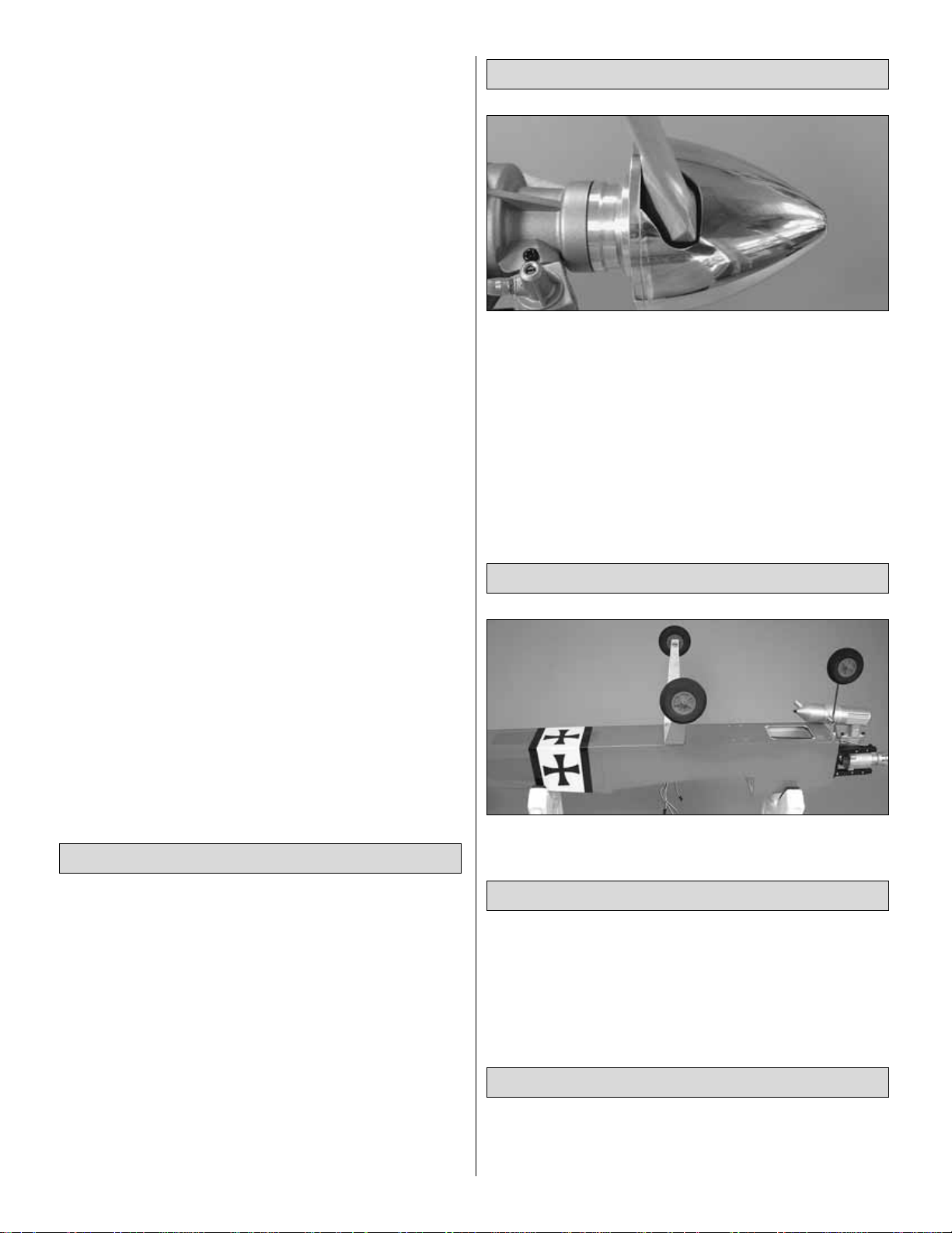
❏ 4. Taildragger: If building your Giant Big Stik ARF as a
taildragger, mount the main landing gear at the forward
mounting location with four 6-32 x 1" [25mm] screws, #6
washers and #6 flat washers.If building your Giant Big Stik
ARF with a nose gear, mount the landing gear in the aft
mounting location. Note that the 90° angle side of the gear
faces forward.
Follow these steps if building your Giant Big Stik ARF
with nose gear. Otherwise, skip to step 1 on page 16.
❏ 5.T ricyc le: Use a metal file, wire cutters or a rotary tool with
a cut-off wheel to grind one edge off of two 6-32 blind nuts.
❏ 6. Tricycle: Apply a few dabs of epoxy to the front of the
two blind nuts, then use a 6-32 x 3/4" [19mm] screw to pull
the nuts into the bottom two holes in the back of the firewall
for the nose gear bearing. Pull two more blind nuts into the
top holes the same way.
❏ 7. Tricycle: Cut apart the two pieces of the nylon nose
gear bearing.
❏ 8. Tricycle: Slide the nose gear wire onto the nose gear
bearings and the steering arm in between.Temporarily mount
the bearings to the firewall with four 6-32 x 3/4" [19mm]
screws, #6 lock washers and #6 flat washers. For now, it
doesn’t matter which side the steering arm is on, but the top
of the nose gear wire should be even with the top bearing.
Mount the Landing Gear
15
Page 16

GLOW ENGINE
❏ 1.Fit the engine to the engine mount halves and hold the
assembly together using small C-clamps. (Since this plane
has no engine cowl it doesn’t matter how far forward or aft
you position the engine on the mount.) Use a Great Planes
Engine Hole Locator or a drill bit to mark the engine
mounting holes into the engine mounts.
❏ 2. Take the engine off the mount. Drill #29 holes at the
marks. Use an 8-32 tap to cut threads into the holes. Mount
the engine to the mount with four 8-32 x 1" [25mm] socket
head cap screws and #8 lock washers.
❏ 3.Temporarily mount the muffler to your engine.Hold the
engine and mount to the firewall to see which way it will be
mounted.As shown in the photo, side mounting is pref erred
as the engine exhaust will be under the fuselage. But in
order to side mount the engine, the muffler must clear the
nose gear and the bottom of the fuselage.If it does not, you
will have to mount the engine a different way. Note: The
engine must be centered laterally on the vertical line on the
firewall, but it is okay to move the engine up, above the
horizontal line in order to clear the nose gear bearing.
❏ 4. Once you have decided which way to mount the
engine, cut out the Glow Engine Mounting Template from
the back of the manual. As the supplied Great Planes
engine mount is adjustable and the mounting bolt holes are
slotted, the crossmarks for the bolt holes on the template
will work for all engines that fit the mount, but the outline
depicts the engine mount “footprint” when an O.S. 1.60 FX
is mounted.
❏ 5. Use tape or spray adhesive to hold the glow engine
mount template to the firewall. As mentioned before, the
vertical line on the template should align with the vertical
line on the firewall, but it is okay if you have to raise the
template so the mount will clear the nose gear bearing. If
the nose gear is not in the way, center the horizontal line on
the template with the horizontal line on the firewall as well.
Use a large T-pin or a wire sharpened on the end to transfer
the bolt hole marks on the template into the firewall.
❏ 6. Drill 13/64" [5.2mm] (or 3/16" [4.8mm]) holes at the
marks. Apply a few dabs of epoxy to the front of four 8-32
blind nuts. Use an 8-32 x 1-1/4" [32mm] bolt with large
washers to draw the blind nuts into the back of the firewall.
❏ 7.Mount the engine mount with the engine to the firewall
using four 8-32 x 1-1/4" [32mm] socket head cap screws
and #8 flat washers and lock washers.
GAS ENGINE (FUJI BT-32)
If mounting a gas engine other than the Fuji BT-32, use
these instructions for ideas how to mount your engine in a
similar manner.
Mount the Engine
16
Page 17

❏ 1. Cut the Fuji BT-32 Engine Mount Template from the
back of the manual 1/16" [1.6mm] outside the dashed lines.
Use tape or repositionable spray adhesive to temporarily
hold the template to the firewall.The hor izontal and vertical
lines on the template should align with the lines on the
firewall. Use a large T-pin or a sharpened wire to mark the
crossmarks for the bolt holes onto the firewall.
❏ 2.Remove the template.Drill 1/8" [3.2mm] pilot holes at the
marks you made.Enlarge the holes with a 19/64" [7.5mm] (or
9/32" [7mm] drill).
❏ 3. Cut or grind the side off two 1/4-20 blind nuts.
❏ 4. Apply epoxy to the front of one of the blind nuts you
just cut off.Use a couple of large washers and a 1/4-20 bolt
to draw the nut into the back of the firewall in one of the
holes on the left side of the fuselage (to clear the aluminum
bracing inside).
❏ 5. Draw the other blind nut into the other hole on the left
side, and two more blind nuts into the remaining two holes
the same way.
❏ 6. Glue together the two 1/4" [6.4mm] plywood Fuji
engine mount plates. Install four 10-32 blind nuts (not
included) in the back of the plate where shown.These will
be for holding the engine to the plate.
❏ 7. Mount the engine mount plate to the firewall with the
included aluminum standoffs, 1/4-20 x 2-1/2" [63mm]
Phillips or hex-head bolts and 1/4" [6.4mm] flat and lock
washers (not included). Do not use socket-head cap
screws–they stick out too far and will interfere with the
engine. Note: The actual standoffs included with your kit
might look different than the ones in the photo.
While we’re working on the front of the fuselage let’s go
ahead and hook up the throttle …
Refer to this photo to install the throttle pushrod.
❏ 8. Drill a 3/16" [4.8mm] hole through the firewall in the
location shown (in the lower left corner for the Fuji BT-32) for
17
Page 18

the throttle pushrod guide tube–this may require temporary
removal of the engine.Drill the hole at an angle so the guide
tube will cross to the other side of the fuselage and so the
pushrod will align with the carburetor arm on the engine.
❏ 9. Cut 17" [430mm] from the 36" [915mm] gray pushrod
guide tube. Use coarse sandpaper to roughen the outside
of the tube so glue will adhere.Slide the guide tube through
the hole in the firewall up into the radio compartment.There
is another hole in the former between the optional landing
gear mounting locations that the guide tube should go into.
❏ 10. Cut the white, plastic throttle pushrod to a length of
23" [585mm]. Connect the pushrod to the carburetor arm
using the hardware shown in the photo.
We’ll connect the other end of the pushrod to the
servo later…
❏ 11. It’s not necessary to do at this moment, but don’t
forget to fuelproof the plywood engine mount plate before
you fly the model.
❏ 1.Remove the stopper from the fuel tank and shake out the
contents. If using a gas engine, follow the instr uctions in the
“Gas Fuel Tank Conversion”
text box that follows this step.
Otherwise, assemble the stopper assembly to suit your
requirements for glow–most applications will require only a
two-line system–one line for the fuel pickup and
fueling/defueling and another line for overflow/muffler
pressure (or for a vent on gas engines).Since the engine and
fuel lines on this model are easy to get to, fueling will be done
through the pickup line.If, however, a third line is required for
fueling/defueling, simply install the third line into the stopper
(additional fuel line and clunk not included with this kit). The
third line will have to be closed after fueling. Install the
aluminum tubes into the stopper as shown in the sketch
above.When it’s time to install the tank and connect the lines
later, you can refer to the sketch so you will know which line
goes to the carb and which line goes to the muffler.
❏ 2. Install the stopper assembly into the tank and tighten
the screw to complete the seal. Make sure the clunk on the
end of the fuel line does not contact the rear of the tankotherwise it may become stuck above the fuel level while
the model is in flight.
Gas Fuel Tank Conversion
1. The hardware necessary to do the gas conversion is
listed in the front of the manual. Substitute the included
aluminum fuel line tubes with 1/8" brass tubing. Cut the
vent tube and the pickup tube to the correct length, then
solder fuel line barbs onto one end of the tubes. Install
the tubes into the stopper assembly, then solder another
fuel line barb onto the other end of the pickup tube.
2.Connect the clunk to the pickup tube via a piece of gascompatible fuel line (not included).
Install the Fuel Tank
18
Page 19

❏ 3. Determine how far forward or aft you will be mounting
the fuel tank in the fuel tank compartment.The tank may be
positioned to accommodate a battery pack for the electronic
ignition system should you be using one on a spark-ignition
(gas) engine. Glue the plywood top fuel tank formers into
position so they will support the tank–be certain to glue the
aft former behind the forward for mer.
❏ 4. Fit the tank into the fuel tank compartment. Connect the
fuel lines (not included) to the tank, then guide the lines through
the hole in the middle of the firewall and connect them to the
carburetor and the pressure fitting on the muffler (on glow
engines). Temporar ily lift the tank out of the way, then apply a
few dabs of RTV silicone to the top fuel tank formers and drop
the tank back into position.Apply a few dabs of RTV silicone to
the bottom fuel tank formers, then glue them into position.
The nose gear steering and throttle are installed
simultaneously. Refer to the following photos for
installation. (Remember, the unused servo arms won’t
be trimmed from the four-arm servo arms until setting
up the radio later.)
❏ 1. If you’ve installed a Fuji engine, the throttle pushrod is
already connected to the engine. If you are using a glow
engine and have not yet installed the throttle pushrod, drill
a 3/16" [4.8mm] hole through the firewall for the throttle
pushrod guide tube. (If you don’t have an extended drill bit
the engine will have to be removed–or you could drill the
hole with a 3/16" [4.8mm] brass tube sharpened on the
end). As best as you can, position the hole so the throttle
pushrod will align with the carburetor arm–it doesn’t have to
be perfect because you will be able to bend the pushrod
later.Be certain you do not drill into the fuel tank.
❏ 2. Cut 17" [430mm] from the 36" [915mm] gray pushrod
guide tube. Use coarse sandpaper to roughen the outside
of the tube so glue will adhere.Slide the guide tube through
the hole you drilled in the firewall and through the holes in
the other two formers in the fuselage.
❏ 3. Thread a nylon clevis onto a 36" [915mm] wire
pushrod. Star t out by cutting the pushrod to a length of 27"
[685mm], then mount the throttle servo in the fuselage and
hook up the throttle using the hardware shown. Bend the
pushrod as necessary to connect it to the brass screw-lock
connector carburetor arm, then cut the pushrod
approximately 3/8" [9.5mm] past the connector.
❏ 4. If you are building your Giant Big Stik ARF with nose
gear, use another 36" [915mm] pushrod, the remainder of
the 3/16" [4.8mm] guide tube and the same hardware to
hook up the nose gear steering. Mount the nose gear
steering servo.It will be easiest to position the steering arm
on the side opposite the throttle pushrod-there are two slots
in the firewall for the pushrod–use the one that works best
for your setup.
❏ 5. Once the throttle and nose steering are connected,
use medium CA to glue the guide tubes in place. Don’t
Hook Up the Throttle & Nose
Gear Steering
19
Page 20

forget to temporarily remove the servo mounting screws,
harden the holes with thin CA, allow to harden, then
reinstall the screws.
❏ 6. If you’ve installed the nose gear, temporarily remove
the nose gear wire and file a flat spot for the screw in the
steering arm. Reinstall the wire and tighten the 6-32 x 1/4"
[6.4mm] screw with a drop of threadlocker.
❏ 7.Position the fuel tank hatch o ver its opening. Using the
holes already in the hatch as a guide, drill 1/16" [1.6mm]
holes into the support ledge. Mount the hatch with four #2 x
3/8" screws and #2 washers. Remove the screws and
hatch, harden the holes with thin CA, allow to harden, then
mount the hatch.
❏ 1. Connect one 36" [910mm] ser vo extension to each
servo for the elevator and r udder. Secure the connections
with heat shrink tubing.Guide the servo wires down through
the fuselage and mount the servos using the same
procedures used for mounting servos all along (don’t forget
to harden the screw holes with thin CA).
❏ 2.Make the pushrods and hook up the rudder and elev ator
using the same hardware used for the flaps and ailerons.Be
certain to distance the elevator control horn far enough away
from the rudder so that the two will not interfere.
❏ 1. Cut the 1/4" x 1/4" x 8" [6.4 x 6.4 x 200mm] hardwood
mounting rails into two 4" [100mm] pieces. Cut the 1/16" x
1" x 6" [1.6 x 25 x 150mm] balsa rail support into two 3"
[75mm] pieces.
❏ 2.A plywood receiver/battery tray is included with this kit.
For C.G.considerations, the tray may be mounted ahead of
or behind former 3.If using a glow engine, mount the tray in
the forward location.If using a gas engine, mount the tray in
the aft location. Tr im the 1/16" x 1" x 3" [1.6 x 25 x 75mm]
balsa rail supports as necessary to position the rails at the
desired height in the fuselage. For the model shown in this
manual, the supports were cut to a width of 1/2" [13mm].
Glue the rail supports and the rails into position.
❏ 3.Test mount the receiv er/battery tray to the rails by drilling
1/16" [1.6mm] holes through the rails and screwing them in
place with four #2 x 3/8" [9.5mm] screws and #2 washers.
Mount the Receiver & Battery
GET THE MODEL READY TO FLY
Hook Up the Elevator & Rudder Servos
20
Page 21

❏ 4. Take the tray out of the fuselage, then use the included
V elcro strips and R/C foam rubber (not included) to mount the
receiver and battery. Add a few drops of thin CA to the screw
holes, allow the glue to harden, then mount the tra y bac k into
the fuselage.
❏ 5. Mount the receiver on/off switch in a location that is
easily accessible and will not get coated by engine e xhaust.
A Great Planes Switch & Charge Jack Mounting Set
(GPMM1000) was used on this model and is a great way to
easily connect to the battery pack for voltage monitoring.
❏ 6. Connect the servos in the fuselage to the receiver.
Guide the receiver antenna awa y from the servos and on/off
switch and down through the antenna tube that is factorybuilt into the fuselage. Note the Y-connectors connected to
the receiver for the flaps and ailerons.
With the radio system connected and operating, turn on the
transmitter and receiver. Make sure the trims on the
transmitter are centered.Starting with the rudder servo, test
fit the four-arm servo arm in one of the four positions until
you find the one that is 90-degrees. Cut off the remaining
arms.Repeat this procedure for the rest of the servos.Note:
For this procedure, the flap servos cannot be connected to
a function operated by a two-position switch. Temporarily
connect the flap servos to a function that has a center (such
as one of the control sticks or a slider) to find the servo arm
that will be 90-degrees.
❏ 1. With the transmitter and receiver still on, check all the
control surfaces to see if they are centered.If necessary, adjust
the clevises on the pushrods to center the control surfaces.
❏ 2.Make certain that the control surfaces and the carburetor
respond in the correct direction as shown in the diagram. If
any of the controls respond in the wrong direction, use the
Check the Control Directions
Center the Servos
21
4-CHANNEL RADIO SETUP
(STANDARD MODE 2)
4-CHANNEL
ELEVATOR MOVES UP
RIGHT AILERON MOVES UP
LEFT AILERON MOVES DOWN
TRANSMITTER
4-CHANNEL
TRANSMITTER
RUDDER MOVES RIGHT
CARBURETOR WIDE OPEN
4-CHANNEL
TRANSMITTER
4-CHANNEL
TRANSMITTER
Page 22

servo reversing in the transmitter to reverse the servos
connected to those controls. Be certain the control surfaces
have remained centered.Adjust if necessary.
Use a Great Planes AccuThrow™(or a ruler) to accurately
measure and set the control throw of each control surface
as indicated in the chart that follows. If your radio does not
have dual rates, we recommend setting the throws at the
high rate setting. Note: The throws are measured at the
widest part of each control surface.
Note: If you’ve set up your Giant Big Stik ARF with flaps,
1/8" [3mm] of down elevator mixing is recommended with
the half-flap setting and 1/4" [6mm] of down elevator is
recommended with the full-flap setting. Without this down
elevator mixing, the nose will noticeably pitch upward when
the flaps are extended.
At this stage the model should be in ready-to-fly condition
with all of the systems in place including the engine, landing
gear, cover ing and paint, and the radio system.
❏ 1. Temporarily join the wings with the joiner tube. If you
will be using a Great Planes C.G. Machine to balance the
model, set the rulers to 5-7/8" [150mm], then mount the
wing to the fuselage and proceed to the next step.If you will
not be using a C.G.Machine, use a fine-point felt-tip pen to
accurately mark the C.G. on the bottom of the wing 5-7/8"
[150mm] back from the leading edge.Lay a piece of narrow
(1/8" [2mm]) tape over the line so you will be able to feel it
with your fingers when lifting the model to check the C.G.
This is where your model should balance for the first
flights. Later, you may wish to experiment by shifting the
C.G. up to 5/8" [16mm] forward or back to change the
flying characteristics. Moving the C.G. forward may
improve the smoothness and stability, but the model may
then require more speed for takeoff and make it more
difficult to slow for landing.Moving the C .G.aft makes the
model more maneuverable, but could also cause it to
become too difficult to control. In any case, start at the
recommended balance point and do not at any time
balance the model outside the specified range.
More than any other factor, the C.G. (balance point) can
have the greatest effect on how a model flies, and may
determine whether or not your first flight will be
successful. If you value this model and wish to enjoy it for
many flights, DO NOT OVERLOOK THIS IMPORTANT
PROCEDURE. A model that is not properly balanced will
be unstable and possibly unflyable.
Balance the Model (C.G.)
IMPORTANT: The Giant Big Stik ARF has been
extensively flown and tested to arrive at the throws at
which it flies best. Flying your model at these throws will
provide you with the greatest chance for successful first
flights. If, after you have become accustomed to the way
the Giant Big Stik ARF flies, you would like to change the
throws to suit your taste, that is fine. However, too much
control throw could make the model difficult to control, so
remember, “more is not always better.”
These are the recommended control surface throws:
High Rate Low Rate
ELEVATOR: 3/4" [19mm] up 1/2" [13mm] up
3/4" [19mm] down 1/2" [13mm] down
RUDDER: 3" [76mm] right 1-1/2" [38mm] right
3" [76mm] left 1-1/2" [38mm] left
AILERONS: 1-1/4" [32mm] up 1" [25mm] up
1-1/4" [32mm] down 1" [25mm] down
FLAPS: 1-5/8" [42mm] full
13/16" [21mm] half
Set the Control Throws
22
Page 23

❏ 2.With the wing attached to the fuselage, all parts of the
model installed (ready to fly) and an empty fuel tank, place
the model on the CG Machine or lift it at the balance point
you marked.
❏ 3.If the tail drops, the model is “tail heavy”and weight must
be added to the nose to balance.If the nose drops, the model
is “nose heavy” and weight must be added to the tail to
balance. If possible, relocate the battery pack and receiver to
minimize or eliminate any additional ballast required. If
additional weight is still required and you are using a glow
engine, nose weight may be easily added by using a “spinner
weight”(GPMQ4645 for the 1 oz.[28g] weight, or GPMQ4646
for the 2 oz.[57g] weight).If spinner weight cannot be used or
is not enough, use Great Planes (GPMQ4485) “stick-on”lead.
To find out just how much weight is needed, begin by placing
incrementally increasing amounts of weight on the fuselage
where needed until the model balances. Once you have
determined the amount of weight required, it can be
permanently attached. A good place to add stick-on nose
weight is inside the fuel tank compartment.
If tail weight is required, it may be added by cutting open the
bottom of the fuselage and gluing it permanently inside.
Note: Do not rely upon the adhesive on the back of the lead
weight to permanently hold it in place. Over time, fuel and
exhaust residue may soften the adhesive and cause the
weight to fall off. Use #2 sheet metal screws, RTV silicone
or epoxy to permanently hold the weight in place.
❏ 4. IMPORTANT: If you found it necessary to add any
weight, recheck the C.G.after the weight has been installed.
❏ 1. With the wings level, have an assistant help you lift the
model by the engine propeller shaft and the bottom of the
fuselage under the trailing edge of the fin.Do this sev eral times.
❏ 2.If one wing always drops when you lift the model, it means
that side is heavy. Balance the airplane by adding weight to the
other wing tip. An airplane that has been laterally balanced
will track better in loops and other maneuvers.
No matter if you fly at an AMA sanctioned R/C club site or if you
fly somewhere on your own, you should always have your
name, address, telephone number and AMA number on or
inside your model.It is required at all AMA R/C club flying sites
and AMA sanctioned flying events. Fill out the identification tag
on page 28 and place it on or inside your model.
Follow the battery charging instructions that came with your
radio control system to charge the batteries. You should
always charge your transmitter and receiver batteries the
night before you go flying, and at other times as
recommended by the radio manufacturer.
CAUTION: Unless the instructions that came with your
radio system state differently, the initial charge on new
transmitter and receiver batteries should be done for
fifteen hours using the slow-charger that came with the
radio system.This will “condition” the batteries so that the
next charge may be done using the fast-charger of your
choice. If the initial charge is done with a fast-charger the
batteries may not reach their full capacity and you may be
flying with batteries that are only partially charged.
Charge the Batteries
Identify Y our Model
PREFLIGHT
Balance the Model Laterally
23
Page 24

Carefully balance your propeller and spare propellers before
you fly. An unbalanced prop can be the single most
significant cause of vibration that can damage your model.
Not only will engine mounting screws and bolts loosen,
possibly with disastrous effect, but vibration may also
damage your radio receiver and battery. Vibration can also
cause your fuel to foam, which will, in turn, cause your
engine to run hot or quit.
We use a Top Flite Precision Magnetic Prop Balancer
™
(TOPQ5700) in the workshop and keep a Great Planes
Fingertip Prop Balancer (GPMQ5000) in our flight box.
If the engine is new, follow the engine manufacturer’s
instructions to break-in the engine. After break-in, confir m
that the engine idles reliably, transitions smoothly and
rapidly to full power and maintains full power-indefinitely.
After you run the engine on the model, inspect the model
closely to make sure all screws remained tight, the hinges
are secure, the prop is secure and all pushrods and
connectors are secure.
Ground check the operational range of your r adio bef ore the
first flight of the day. With the transmitter antenna collapsed
and the receiver and transmitter on, you should be able to
walk at least 100 feet away from the model and still have
control. Have an assistant stand by your model and, while
you work the controls, tell you what the control surfaces are
doing. Repeat this test with the engine r unning at var ious
speeds with an assistant holding the model, using hand
signals to show you what is happening. If the control
surfaces do not respond correctly, do not fly! Find and
correct the problem first. Look for loose servo connections
or broken wires, corroded wires on old servo connectors,
poor solder joints in your battery pack or a defective cell, or
a damaged receiver crystal from a previous crash.
Keep all engine fuel in a safe place, away from high heat,
sparks or flames, as fuel is very flammable. Do not smoke
near the engine or fuel; and remember that engine exhaust
gives off a great deal of deadly carbon monoxide .Therefore,
do not run the engine in a closed room or garage.
Get help from an experienced pilot when learning to
operate engines.
Use safety glasses when starting or running engines.
Do not run the engine in an area of loose gravel or sand;the
propeller may throw such material in your face or eyes.
Keep your f ace and body as well as all spectators a wa y from
the plane of rotation of the propeller as you start and run
the engine.
Keep these items away from the prop: loose clothing, shirt
sleeves, ties, scarfs, long hair or loose objects such as
pencils or screwdrivers that may fall out of shir t or jacket
pockets into the prop.
Use a “chicken stick” or electric starter to star t the engine.
Do not use your fingers to flip the propeller .Make certain the
glow plug clip or connector is secure so that it will not pop
off or otherwise get into the running propeller.
Make all engine adjustments from behind the rotating propeller .
The engine gets hot! Do not touch it during or right after
operation.Make sure fuel lines are in good condition so fuel
will not leak onto a hot engine, causing a fire.
To stop a glow engine, cut off the fuel supply by closing off
the fuel line or following the engine manufacturer’s
recommendations. Do not use hands, fingers or any other
body part to try to stop the engine. To stop a gasoline
powered engine an on/off switch should be connected to the
engine coil. Do not throw anything into the propeller of a
running engine.
Read and abide by the following e xcerpts from the Academy
of Model Aeronautics Safety Code.For the complete Safety
Code refer to
Model Aviation
magazine, the AMA web site
or the Code that came with your AMA license.
AMA SAFETY CODE (excerpts)
Failure to follow these safety precautions may result
in severe injury to yourself and others.
ENGINE SAFETY PRECAUTIONS
Range Check
Ground Check
Balance the Propellers
24
Page 25

GENERAL
1) I will not fly my model aircraft in sanctioned events, air
shows, or model flying demonstrations until it has been
proven to be airworthy by having been previously,
successfully flight tested.
2) I will not fly my model aircraft higher than approximately
400 feet within 3 miles of an airport without notifying the
airpor t operator. I will give right-of-way and avoid flying in
the proximity of full-scale aircraft. Where necessary, an
observer shall be utilized to supervise flying to avoid having
models fly in the proximity of full-scale aircraft.
3) Where established, I will abide by the safety rules for the
flying site I use, and I will not willfully and deliberately fly my
models in a careless, reckless and/or dangerous manner.
5) I will not fly my model unless it is identified with my name
and address or AMA number, on or in the model.Note: This
does not apply to models while being flown indoors.
7) I will not operate models with pyrotechnics (any device
that explodes, burns, or propels a projectile of any kind).
RADIO CONTROL
1) I will have completed a successful radio equipment ground
check before the first flight of a new or repaired model.
2) I will not fly my model aircraft in the presence of
spectators until I become a qualified flier, unless assisted b y
an experienced helper.
3) At all flying sites a straight or curved line(s) must be
established in front of which all flying takes place with the
other side for spectators.Only personnel involved with flying
the aircraft are allowed at or in the front of the flight line.
Intentional flying behind the flight line is prohibited.
4) I will operate my model using only radio control frequencies
currently allowed by the F ederal Comm unications Commission.
5) I will not knowingly operate my model within three
miles of any pre-existing flying site except in
accordance with the frequency sharing agreement
listed (in the complete AMA Safety Code).
9) Under no circumstances may a pilot or other person
touch a powered model in flight;nor should any part of the
model other than the landing gear intentionally touch
the ground, except while landing.
Since the Giant Big Stik ARF qualifies as a “giant-scale”
model and is therefore eligible to fly in IMAA events,
we’ve printed excerpts from the IMAA Safety Code
which follow.
What is Giant-Scale?
The concept of large or giant-scale is generally considered
to apply to radio controlled model aircraft with minimum
wingspans of 80 inches for monoplanes and 60 inches for
multi-wing aircraft. Quarter-scale or larger replicas of
person-carrying aircraft with proper documentation
(minimum 3-view drawing) which do not fit the size
requirements will also be permitted.
SECTION 1.0: SAFETY STANDARD
1.1 Adherence to Code: The purpose of this Safety Code is
to provide a structure whereby all participants, including
spectators, will be aware of the inherent dangers in the
operation of radio controlled aircraft.This code is meant
to serve as a minimum guideline to all participants. It is
understood that the ultimate responsibility for the safety
of any aircraft lies with the owner(s), pilot(s) and
spectator(s) involv ed in any event. It is the responsibility
of all participants to exercise caution when operating, or
observing the operation of all radio controlled aircraft.
The pilot/owner of an aircraft will not be dissuaded from
taking whatever steps the y deem necessary, in addition
to this code, to insure that their aircraft is safe.
1.2 The most current AMA Safety Code in effect is to
be observed.
SECTION 3.0: SAFETY REVIEW
3.4 Flight Testing: All aircraft are to have been flight tested
and flight trimmed with a minimum of six (6) flights
before the model is allowed to fly at an IMAA
Sanctioned event.
3.5 Proof of Flight: The completing and signing of the
Declaration section of the Safety Review form (see
Section 3.2) by the pilot (or owner) shall document, as
fact, that the noted aircraft has been successfully flight
tested and proven airworthy prior to the IMAA event.
Section 4.0: SPOTTER/HELPER
4.1 Spotter/Helper Definition: An assistant to aid the pilot
during start-up, and taxing onto the runway. The
spotter/helper will assist the pilot in completing a safe flight.
4.2 Each pilot is required to have a spotter/helper at all
IMAA sanctioned events. The event Safety Committee
should be prepared to assist those pilots who do not
have a spotter/helper to make sure that every
registered pilot has the opportunity to fly at a
sanctioned event.
SECTION 5.0: EMERGENCY ENGINE SHUT OFF
(Kill Switch)
5.1 Magneto spark ignition engines must have a coilgrounding switch on the aircraft to stop the engine.This
will also prevent accidental starting of the engine.This
switch shall be readily available to both pilot and
spotter/helper. This switch is to be operated manually
and without the use of the Radio System.
5.2 Engines with battery powered ignition systems must
have a switch to turn off the power from the battery
pack to disable the engine from firing. This will also
prevent accidental starting of the engine. This switch
IMAA SAFETY CODE (excerpts)
25
Page 26

shall be readily available to both pilot and
spotter/helper. This switch shall be operated manually
and without the use of the Radio System.
5.3 There must also be a means to stop the engine from
the transmitter. The most common method is to
completely close the carburetor throat using throttle
trim; however, other methods are acceptable. This
requirement applies to all glow/gas ignition engines
regardless of size.
SECTION 6.0: RADIO REQUIREMENTS
6.1 All transmitters must be FCC type certified.
6.2 FCC Technician or higher-class license required for 6
meter band operation only.
The following recommendations are included in the Safety
Code not to police such items, but rather to offer basic
suggestions for enhanced safety. It is expected that IMAA
members will avail themselv es of technological advances as
such become available, to promote the safety of all aircraft
and participants.
Servos need to be of a rating capable to handle the loads
that the control surfaces impose upon the servos.Standard
servos are not recommended for control surfaces. Ser vos
should be rated heavy-duty ounces of torque. For flight
critical control functions a minimum of 45 inch/ounces of
torque should be considered. This should be considered a
minimum for smaller aircraft and higher torque servos are
strongly encouraged for larger aircraft.The use of one servo
for each aileron and one for each stabilizer half is strongly
recommended. Use of dual servos is also recommended on
larger aircraft.
On-board batteries should be, at a minimum, 1000mAh up
to 20 lbs., 1200mAh to 30 lbs., 1800mAh to 40 lbs., and
2000mAh over 40 lbs.flying weight.The number and size of
servos, size and loads on control surfaces, and added
features should be considered as an increase to these
minimums. Batteries should be able to sustain power to the
on-board radio components for a minimum of one hour total
flying time before recharging.
Dependable, redundant and fail safe battery systems
are recommended.
The use of anti-glitch devices for long leads is recommended.
There is no maximum engine displacement limit, as it is the
position of this body that an underpowered aircraft presents
a greater danger than an overpowered aircraft.However , the
selections of engine size relative to airframe strength and
power loading mandates good discretionary judgment by
the designer and builder. Current AMA maximums for
engine displacement are 6.0 cu. in. for two stroke and 9.6
cu. in. for four stroke engines.These maximums apply only
to AMA Sanction competition events such as 511, 512, 515
and 520. All non competition events should be sanctioned
as Class C events , in which these engine size maximums do
not apply.
Generally, it is recommended that no attempt should be made
to fly a radio controlled model aircraft with a gasoline engine in
which the model aircraft weight would exceed 12 pounds per
cubic inch of engine displacement (underpowered), or be less
than 5 pounds per cubic inch of engine displacement
(overpowered). Example: Using a 3 cu. in. engine, a model
would likely be underpowered at an aircraft weight greater
than 36 pounds. With the same engine, an aircraft weighing
less than 15 pounds would likely be overpowered.
Servo arms and control horns should be rated heavy-duty.
Glass-filled servo arms and control horns are
highly recommended.
Control surface linkages are listed in order of preference:
1. Cable system (pull-pull). A tiller bar is highly
recommended along with necessary bracing.
2. Arrow-shaft, fiberglass or aluminum, 1/4" [6.4mm] or
5/16" [8mm] OD .Bracing every six (6) to ten (10) inches
is highly recommended.
3. Tube in tube (Nyrod). Bracing every few inches is highly
recommended. Inner tube should be totally enclosed in
outer tube.
4. Hardwood dowel, 3/8" OD. Bracing every six (6) to ten
(10) inches is highly recommended.
Hinges should be rated heavy-duty and manufactured
primarily for use in giant-sized aircraft. Homemade and
original design hinges are acceptable if determined to be
adequate for the intended use.
Clevis (steel, excluding heavy-duty ball links) and
attachment hardware should be heavy-duty 4-40 threadand-rod type. 2-56 Thread size rod is acceptable for some
applications (e.g.throttle). Clevises must have lock nuts and
sleeve (fuel tubing) or spring keepers.
Propeller tips should be painted or colored in a visible and
contrasting manner to increase the visibility of the propeller
tip arc.
❏ 1. Fuelproof all areas exposed to fuel or exhaust residue
such as the wing saddle area, the framework around
the fuel tank hatch, the top of the fuel tank hatch, etc.
During the last few moments of preparation your mind may
be elsewhere anticipating the excitement of the first flight.
Because of this, you may be more likely to overlook certain
checks and procedures that should be performed before the
model is flown.T o help avoid this, a check list is provided to
make sure these important areas are not overlooked.Many
are covered in the instruction manual, so where
appropriate, refer to the manual for complete instructions.
Be sure to check the items off as they are completed.
CHECK LIST
26
Page 27

❏ 2. Double-check the C.G. according to the
measurements provided in the manual.
❏ 3. Be certain the battery and receiver are securely
mounted in the fuselage. Simply stuffing them into
place with foam rubber is not sufficient.
❏ 4. Extend your receiver antenna and make sure it has
been guided up through the antenna tube.
❏ 5. Balance your model
laterally
as explained in
the instructions.
❏ 6. Use thread-locking compound to secure critical
fasteners such as the set screws in the wheel collars,
screw-lock pushrod connectors, etc.
❏ 7. Add a drop of oil to the axles so the wheels will
turn freely.
❏ 8. Make sure all hinges are securely glued in place.
❏ 9. Reinforce holes for wood screws with thin CA where
appropriate (servo mounting screws, receiver/battery
tray mounting screws, etc.).
❏ 10. Confirm that all controls operate in the correct
direction and the throws are set up according to
the manual.
❏ 11. Make sure there are silicone retainers on all the
clevises and that all servo arms are secured to the
servos with the screws included with your radio.
❏ 12.Secure connections between servo wires and
Y-connectors or servo extensions, and the
connection between your battery pack and the on/off
switch with vinyl tape, heat shrink tubing or special
clips suitable for that purpose.
❏ 13. Make sure any servo extension cords you may have
used do not interfere with other systems (servo arms,
pushrods, etc.).
❏ 14. Make sure the fuel lines are connected and are
not kinked.
❏ 15. Balance your propeller (and spare propellers).
❏ 16. Tighten the propeller nut and spinner.
❏ 17.Place your name, address, AMA number and
telephone number on or inside your model.
❏ 18. Cycle your receiver battery pack (if necessary) and
make sure it is fully charged.
❏ 19. If you wish to photograph your model, do so before
your first flight.
❏ 20. Range check your radio when you get to the flying field.
The Giant Big Stik ARF is a great-flying model that flies
smoothly and predictably. The Giant Big Stik ARF does not,
however, possess the self-recovery characteristics of a
primary R/C trainer and should be flown only by
experienced R/C pilots.
Before you get ready to takeoff, see how the model handles
on the ground and make sure it steers straight by doing a
few practice runs at low speeds on the runway. If you built
your Giant Big Stik ARF as a taildragger, hold a little “up”
elevator to keep the tail wheel on the ground. If you built it
with tricycle gear, keep the elevator neutral or hold a little bit
of down to hold the nose on the ground.If necessary, adjust
the tail wheel (or nose wheel) so the model will roll straight
down the runway. Double-check all pushrod connections to
make sure they are all secure.
Remember to takeoff into the wind. When ready, point the
model straight down the runway, hold elevator as necessary
to keep whichever wheel is doing the steering (nose or tail)
on the ground, then gradually advance the throttle.
Taildraggers: As the model gains speed decrease up
elevator, allowing the tail to come off the ground. One of the
most important things to remember with a taildragger is to
always be ready to apply right rudder to counteract engine
torque. Gain as much speed as your runway and flying site
will practically allow before gently applying up elevator,
lifting the model into the air. At this moment it is likely that
you will need to apply more right rudder to counteract
engine torque.Be smooth on the elevator stick, allowing the
model to establish a gentle climb to a safe altitude before
turning into the traffic pattern.
Take Off
CAUTION (THIS APPLIES TO ALL R/C AIRPLANES): If,
while flying, you notice an alarming or unusual sound
such as a low-pitched “buzz,” this may indicate control
surface
flutter
. Flutter occurs when a control surface
(such as an aileron or elevator) or a flying surface (such
as a wing or stab) rapidly vibrates up and down (thus
causing the noise). In extreme cases, if not detected
immediately, flutter can actually cause the control surface
to detach or the flying surface to fail, thus causing loss of
control followed by an impending crash.The best thing to
do when flutter is detected is to slow the model
immediately by reducing power, then land as soon as
safely possible. Identify which surface fluttered (so the
problem may be resolved) by checking all the servo
grommets for deterioration or signs of vibration. Make
certain all pushrod linkages are secure and free of play. If
it fluttered once, under similar circumstances it will
probably flutter again unless the problem is fixed. Some
things which can cause flutter are; Excessive hinge gap;
Not mounting control horns solidly; Poor fit of clevis pin in
horn; Side-play of wire pushrods caused by large bends;
Excessive free play in servo gears; Insecure servo
mounting;and one of the most prevalent causes of flutter;
Flying an over-powered model at excessive speeds.
FLYING
27
Page 28

For reassurance and to keep an eye on other traffic, it is a
good idea to have an assistant on the flight line with you.Tell
him to remind you to throttle back once the plane gets to a
comfortable altitude. While full throttle is usually desirable for
takeoff, most models fly more smoothly at reduced speeds.
Take it easy with your Giant Big Stik ARF for the first few
flights, gradually getting acquainted with it as you gain
confidence. Adjust the trims to maintain straight and level
flight. After flying around for a while, and while still at a safe
altitude with plenty of fuel, practice slow flight and execute
practice landing approaches by reducing the throttle to see
how the model handles at slower speeds.Add power to see
how she climbs as well. Continue to fly around, executing
various maneuvers and making mental notes (or having
your assistant write them down) of what trim or C.G.
changes may be required to fine tune the model so it flies
the way you like. Mind your fuel level, but use this first flight
to become familiar with your model before landing.
To initiate a landing approach, lower the throttle while on the
downwind leg.Allow the model to slow before extending the
flaps. If executing your first landing with flaps you could try
the half-flap setting. When using flaps, it’s also a good idea
to keep a few extra “clicks” of power to maintain airspeed.
Allow the nose of the model to pitch downward to gradually
bleed off altitude. Continue to lose altitude, but maintain
airspeed by keeping the nose down as you turn onto the
crosswind leg. Make your final turn toward the runway (into
the wind) keeping the nose down to maintain airspeed and
control. Level the attitude when the model reaches the
runway threshold, modulating the throttle as necessary to
maintain your glide path and airspeed. If you are going to
overshoot, smoothly advance the throttle (always ready on
the right rudder to counteract torque) and climb out, then
retract the flaps and go around to make another attempt.
When you’ re ready to make y our landing flare and the model
is a foot or so off the deck, smoothly increase up elevator
until it gently touches down. Once the model is on the
runway and has lost flying speed, hold elevator as needed
(up or down depending on if you built a nose gear or a
taildragger) to hold the wheel that is doing the steering on
the ground.
One final note about flying your model.Have a goal or flight
plan in mind for every flight. This can be learning a new
maneuver(s), improving a maneuver(s) y ou already know, or
learning how the model behaves in certain conditions (such
as on high or low rates).This is not necessarily to improve
your skills
(though it is never a bad idea!)
, but more
importantly so you do not surprise yourself by impulsively
attempting a maneuver and suddenly finding that you’v e run
out of time, altitude or airspeed. Every maneuver should be
deliberate, not impulsive.For example, if you’re going to do
a loop, check your altitude, mind the wind direction
(anticipating rudder corrections that will be required to
maintain heading), remember to throttle back at the top, and
make certain you are on the desired rates (high/low rates).
A flight plan greatly reduces the chances of crashing your
model just because of poor planning and impulsive moves.
Remember to think.
Have a ball! But always stay in control and fly in a
safe manner.
GOOD LUCK AND GREAT FLYING!
Fill in and place on or inside your model.
Great Planes U-Can-Do 3D™60 ARF
Assembly time is only 6-8 hours, from workbench to “Wow!”
The interlocking airframe is built from hand-selected woods,
the hardware is Great Planes-brand, and the factory-applied
covering is Top Flite MonoKote. Ser vos for each elevator and
aileron offer added authority and tuning possibilities. Exterior
mounting for control surface servos keeps linkages short and
direct and response swift and strong.With an engine from the
high end of the range and maxed throws, the U-Can-Do 60
ARF is everything a 3D star should be.GPMA1270
OTHER ITEMS AVAILABLE FROM
GREAT PLANES
Landing
Flight
28
Page 29

Great Planes Giant Super Chipmunk 1.20 ARF
Art Scholl performed airshow magic with his Super
Chipmunk for over 25 years. And with the help of Great
Planes’ magic, you can have this scale replica ready to
perform in just 12-15 hours. The tr im scheme is authentic,
provided by MonoKote on the built-up wings and stab and
paint on the fiberglass fuselage, cowl, wheel pants and
landing gear fairings. Instrument panel decals and a pilot
figure provide extra “eye candy” without extra work. Routing
tubes for pushrods, a 3-piece wing and a steerab le tailwheel
offer added ease on the ground. Dual ser vos on each flap,
aileron and elevator half put the power to dazzle a crowd at
your fingertips. GPMA1303
Manufactured under license by Pennzoil-Quaker State Company,
2004. Hobbico, Inc.2904 Research Rd, Champaign, IL 61826.
Fuji BT-32B 2.1
Gasoline Engine
Fuji Engines are giantscale fav orites, because
each is designed strictly
for R/C by an engineer
who is also a gas
modeler. Throttle
linkages are short and
direct. Mufflers are
compact, custom units
that help preserve scale
looks as they improve
performance. Walbro
carbs are standard, chosen for pinpoint control and
equipped with regulating pumps to ensure consistent fuel
flow at all times. Flywheels, hubs and crankshafts are
dynamically balanced to reduce vibration, stress and
electrical noise. And all operate on a 40:1 gasoline/oil mix,
which helps them last up to four times longer than other
gasoline engines. Includes a Walbro WT407 carb,
Champion RCJ6Y spark plug, firewall mount and rearmounted muffler.FJIG0033
O.S.®Engines 1.60 FX
The 1.60 FX features dual ball bearings for durability and
smooth operation, plus a low crankcase profile that allows
for a proportionally taller, semi-squared head – a design
refinement that increases cooling fin area and improves
heat dispersion. The threaded portion of the crankshaft is
extra-long for more secure prop and spinner nut
engagement, and the needle valve is remotely mounted for
safety during adjustments.The high-speed needle can also
be mounted horizontally, vertically, or separate from the
engine for more installation options! Includes glow plug and
2-year warranty. OSMG0660
Futaba 7CAP 7-Channel
PCM Computer Radio
For virtually the same price
as some 6-channel radios,
you can enjoy 7-channel
versatility and the ease of
Dial-N-Key programming.
Toggle switches are
accessible without taking
your thumbs off the sticks,
or your eyes off of your
model...and can be
assigned to operate
almost any function.
Contrast on the big 72x32 LCD adjusts for maximum visibility,
and programming includes both Basic and Advanced menus
for airplanes and helis.Includes an R138DP receiver , 600mAh
Tx and Rx NiCds, dual output charger and four digital S3151
servos. 72MHz only. FUTJ71**
29
Page 30

30
BUILDING NOTES
Kit Purchased Date: _______________________
Where Purchased: _________________________
Date Construction Started: __________________
Date Construction Finished: _________________
Finished Weight: __________________________
Date of First Flight: ________________________
FLIGHT LOG
Page 31

31
Fuji
BT-32
Fuji BT-32 Engine Mounting Template
Drill 19/64" [7.5mm] (or 9/32" [7.2mm) holes
at the crossmarks for the 1/4-20 blind nuts
that go into the back of the firewall.
Page 32

 Loading...