

Page 1
WARRANTY
Great Planes
®
Model Manufacturing Co. guarantees this kit to be free from defects in both material and workmanship at the date of
purchase.This warranty does not cover any component parts damaged by use or modification. In no case shall Great Planes’ liability
exceed the original cost of the purchased kit. Further, Great Planes reserves the right to change or modify this warranty without notice.
In that Great Planes has no control over the final assembly or material used for final assembly, no liability shall be assumed nor
accepted for any damage resulting from the use by the user of the final user-assemb led product.By the act of using the user-assembled
product, the user accepts all resulting liability.
If the buyer is not prepared to accept the liability associated with the use of this product, the buyer is advised to return this
kit immediately in new and unused condition to the place of purchase.
READ THROUGH THIS MANUAL BEFORE
STARTING CONSTRUCTION. IT CONTAINS
IMPORTANT WARNINGS AND INSTRUCTIONS
CONCERNING THE ASSEMBLY AND USE OF
THIS MODEL.
GPMZ1250 for GPMA1220/1221 V1.0© Copyright 2001
1610 Interstate Drive Champaign, IL 61822
(217) 398-8970, Ext 2
airsupport@greatplanes.com
INSTRUCTION MANUAL
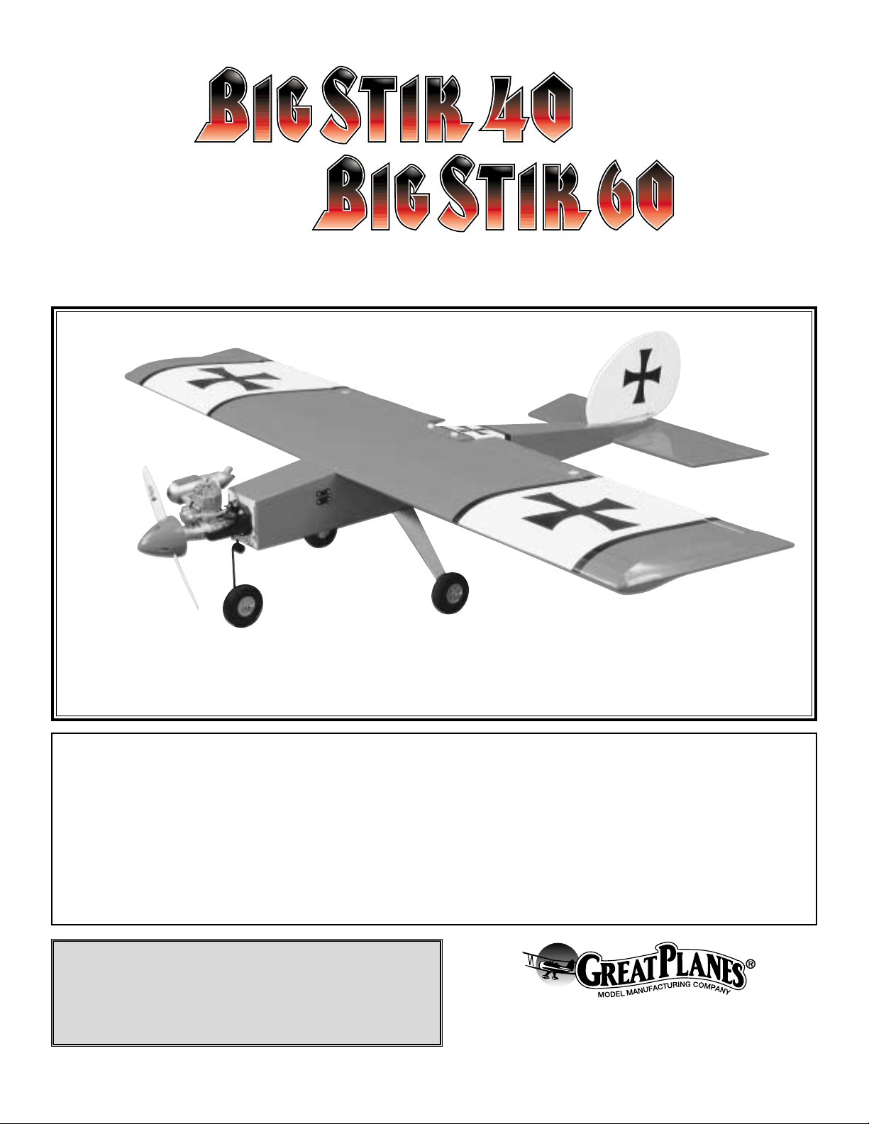
Big Stik .40:
Wingspan: 58.5 in. [1486mm]
Wing Area: 770 sq. in. [49.7 sq dm]
Weight: 5.25 lbs [2380g]
Wing Loading: 15.7 oz./sq. ft.[48 g/sq dm]
Length: 51.5 in. [1308mm]
Radio: 4-Channel with 5 servos
Engine: .40 – .51 2-stroke, .50 – .70 4-stroke
[6.5 – 8.5cc 2-stroke, 8.5 – 11.5cc 4-stroke]
Big Stik .60:
Wingspan: 66.5 in. [1689mm]
Wing Area: 1000 sq. in. [64.5 sq dm]
Weight: 6.5 lbs [2948g]
Wing Loading: 14.97 oz./sq. ft.[46 g/sq dm]
Length: 59 in. [1499mm]
Radio: 4-Channel with 5 servos
Engine: .60 – .91 two-stroke, .91 – .1.20 four-stroke
[10 – 15cc 2-stroke, 15 – 20cc 4-stroke]
Page 2
INTRODUCTION..........................................................................2
SAFETY PRECAUTIONS.............................................................2
DECISIONS YOU MUST MAKE ...................................................3
Radio Equipment..........................................................................3
Engine Recommendations............................................................3
ADDITIONAL ITEMS REQUIRED................................................3
Covering Accessories...................................................................3
Adhesives and Building Supplies .................................................3
Optional Supplies and Tools.........................................................3
IMPORTANT BUILDING NOTES.................................................3
ORDERING REPLACEMENT PARTS .........................................4
METRIC CONVERSION RULER .................................................4
KIT CONTENTS...........................................................................5
WING ASSEMBLY AND INSTALLATION ....................................6
INST ALL THE T AIL COMPONENTS............................................8
TANK INSTALLATION ...............................................................10
ENGINE INSTALLATION ...........................................................10
MOUNT THE LANDING GEAR..................................................12
RADIO INSTALLATION .............................................................13
PROP, SPINNER AND FUEL LINE INSTALLATION .................16
GET THE MODEL READY TO FLY............................................16
Check Control Directions............................................................16
Set the Control Throws ...............................................................17
Balance the Model......................................................................17
Balance the Model Laterally.......................................................18
PREFLIGHT ...............................................................................18
Identify Your Model......................................................................18
Charge the Batteries...................................................................18
Balance the Propellers ...............................................................19
Ground Check.............................................................................19
Range Check..............................................................................19
ENGINE SAFETY PRECAUTIONS............................................19
AMA SAFETY CODE.................................................................19
General.......................................................................................19
Radio Control ..............................................................................20
CHECKLIST ...............................................................................20
FLYING .......................................................................................21
Takeoff ........................................................................................21
Flight...........................................................................................21
Landing.......................................................................................21
The Great Planes Big Stik ARFs are aircraft that let you
progress from your trainer into a model that is not only a
good choice for improving your flying skills but is also great
for high performance aerobatics.
Either plane is a good choice for a second airplane or as an
aerobatic trainer. We are sure that you will enjoy building
and flying the Big Stik ARF.
For the latest technical updates or manual corrections for
the Big Stik ARFs, visit the web site listed below and select
the Great Planes Big Stik ARF. If there is new technical
information or changes to this kit, a “tech notice” box will
appear in the upper left corner of the page.
http://www.greatplanes.com/airplanes/index.html
1. Your Big Stik ARF should not be considered a toy, but
rather a sophisticated, working model that functions very
much like a full-size airplane. Because of its performance
capabilities, the Big Stik ARF, if not assembled and operated
correctly, could possibly cause injury to yourself or
spectators and damage to property.
2. You must assemble the model according to the
instructions. Do not alter or modify the model, as doing so
may result in an unsafe or unflyable model. In a few cases
the instructions may differ slightly from the photos.In those
instances the written instructions should be considered
as correct.
3.You must take time to build straight, true and strong.
4. You must use an R/C radio system that is in first-class
condition and a correctly sized engine and components (fuel
tank, wheels, etc.) throughout the building process.
5.You must correctly install all R/C and other components so
that the model operates correctly on the ground and in the air .
6.You must check the operation of the model before every
flight to insure that all equipment is operating and that the
model has remained structurally sound. Be sure to check
clevises or other connectors often and replace them if they
show any signs of wear or fatigue.
7. If you are not already an experienced R/C pilot, you
should fly the model only with the help of a competent,
experienced R/C pilot.
8.While this kit has been flight tested to exceed normal use,
if the plane will be used for extremely high stress flying, such
as racing, the modeler is responsible for taking steps to
reinforce the high stress points.
Remember:T ake your time and f ollow the instructions to
end up with a well-built model that is straight and true.
If you have not flown this type of model before, we
recommend that you get the assistance of an experienced
pilot in your R/C club for your first flights. If you're not a
We, as the kit manuf acturer, provide you with a top quality
kit and instructions, but ultimately the quality and flyability
of your finished model depends on how you build it;
therefore, we cannot in any way guarantee the
performance of your completed model and no
representations are expressed or implied as to the
performance or safety of your completed model.
PRO TECT YOUR MODEL,YOURSELF
& OTHERS...FOLLOW THESE
IMPORTANT SAFETY PRECAUTIONS
INTRODUCTION
TABLE OF CONTENTS
2
Page 3
member of a club, your local hobby shop has information
about clubs in your area whose membership includes
experienced pilots.
In addition to joining an R/C club, we strongly recommend
you join the AMA (Academy of Model Aeronautics). AMA
membership is required to fly at AMA sanctioned clubs.There
are over 2,500 AMA chartered clubs across the country.
Among other benefits, the AMA provides insurance to its
members who fly at sanctioned sites and events .Additionally,
training programs and instructors are available at AMA club
sites to help you get started the right way. Contact the AMA
at the address or toll-free phone number below:
Academy of Model Aeronautics
5151 East Memorial Drive
Muncie, IN 47302-9252
Tele. (800) 435-9262
Fax (765) 741-0057
Or via the Internet at:
http://www.modelaircraft.org
There are several engines that will work well in your .40 or
.60 sized Big Stik ARF.
For the .40 Big Stik we recommend a 2-stroke engine such
as the O.S.®LA .40, O.S. .40 FX, O.S. .46 FX or the
SuperTigre®G40. For unsurpassed power and realistic
sound, an O.S.FS-70 can't be beat.
For the .60 Big Stik we recommend a 2-stroke engine such
as the O.S. LA .65, O.S. .61 FX or the SuperTigre G61. If
you prefer a f our strok e engine the O.S.FS-70 or O.S.FS-91
are both good choices.
The Great Planes Big Stik ARF .40 and .60 require a good
four channel radio system like the Futaba®4VF. Both
airplanes require a total of five servos each with a minimum
of 44 oz-in of torque.A Y-harness and two 6" servo extensions
are also required.
❏ 21st Centur y
®
sealing iron (COVR2700)
❏ 21st Centur y trim seal iron (COVR2750)
❏ 21st Centur y iron cover (COVR2702)
In addition to common household tools and hobby tools, this
is the “short list” of the most important items required to
build the Big Stik ARF.
Great Planes Pro™CA and Epoxy
glue are recommended.
❏ 2 oz. Pro CA (Thin, GPMR6003)
❏ Propeller (Top Flite
®
Power Point®-Refer To Your Engine's
Instructions For Proper Size)
❏ 2 oz. Pro CA+ (Medium, GPMR6009)
❏ 6-Minute Pro Epoxy (GPMR6045)
❏ 30-Minute Pro Epoxy (GPMR6047)
❏ Epoxy Brushes (GPMR8060)
❏ Mixing Sticks (GPMR8055)
❏ Hobby Knife (HCAR0105), #11 blades (HCAR0211)
❏ Masking T ape (TOPR8018)
❏ 1/4" Latex Foam Rubber Padding (HCAQ1000)
❏ Paper Towels
❏ Drill Bits: 1/16" (1.5mm), 5/64" (2mm), 3/32" (2.4mm),
1/4" (6mm)
❏ Dremel
®
Moto-Tool™with cutoff wheel
❏ 4-40 Tap and drill (Big Stik 40)
❏ 6-32 Tap and drill (Big Stik 60)
Here is a list of optional tools mentioned in the manual that
will help you build the Big Stik ARF.
❏ Switch and Charge Jack (GPMM1000)
❏ Great Planes CG Machine
™
(GPMR2400)
❏ Top Flite Precision Magnetic Prop Balancer
™
(TOPQ5700)
❏ Straightedge with scale (HCAR0475)
❏ CA Debonder (GPMR6039)
❏ CA Applicator tips (GPMR6033)
❏ CA Accelerator (GPMR6034)
❏ Threadlocker (GPMR6060)
❏ Denatured Alcohol (for epoxy clean up)
❏ Builders Triangle Set (HCAR0480) (for fin alignment)
❏ Dead Center
™
Engine Mount Hole Locator (GPMR8130)
❏ Great Planes AccuThrow
™
Deflection Gauge (for
measuring control throws, GPMR2405)
• There are two types of screws used in this kit:
Sheet metal screws are designated by a number and a
length. For example #6 x 3/4"
This is a #6 screw that is 3/4" long.
IMPORTANT BUILDING NOTES
Optional Supplies and Tools
Adhesives and Building Supplies
Covering Accessories
ADDITIONAL ITEMS REQUIRED
Radio Equipment
Engine Recommendations
DECISIONS YOU MUST MAKE
3
Page 4
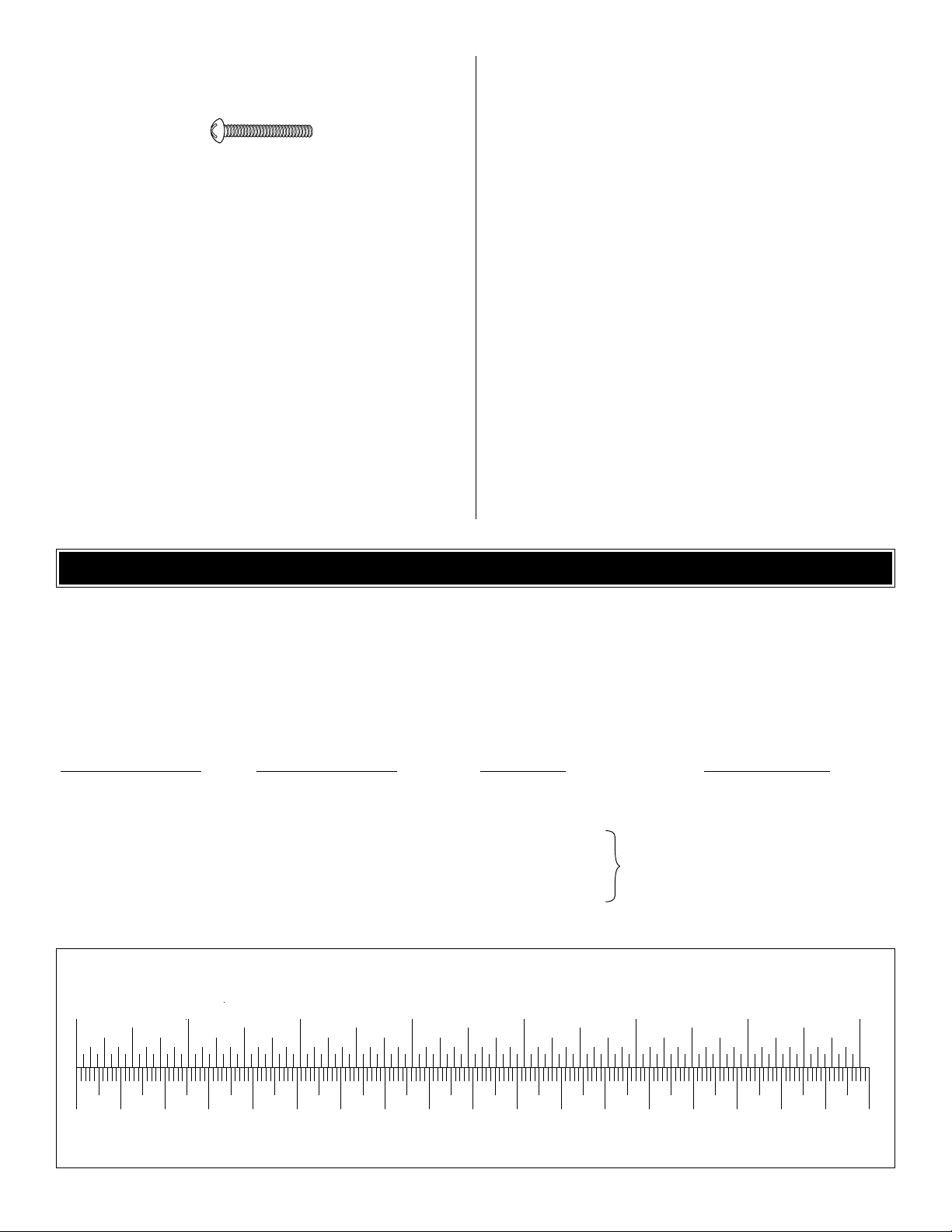
To convert inches to millimeters, multiply inches by 25.4
Machine screws are designated by a number, threads per
inch and a length. For example 4-40 x 3/4"
This is a #4 screw that is 3/4" long with
forty threads per inch.
• During the construction we often refer to the “top” or
“bottom” of the model or a part of the model.It is understood
that the “top”or “bottom” of the model is as it would be when
the airplane is right side up and will be referred to as the
“top” even if the model is being worked on upside-down.
• When you see the term
test fit
in the instructions, it
means that you should first position the part on the
assembly
without using any glue
, then slightly modify or
custom fit
the part as necessar y for the best fit.
• Whenever the term
glue
is written you should rely upon
your experience to decide what type of glue to use.When a
specific type of adhesive works best for that step, the
instructions will make a recommendation.
• Whenever just
epoxy
is specified you may use
either
30-minute (or 45-minute) epoxy or6-minute epoxy. When
30-minute epoxy is specified it is highly recommended that
you use only 30-minute (or 45-minute) epoxy, because you
will need the working time and/or the additional strength.
• Photos and sketches are placed before the step they
refer to. Frequently you can study photos in following steps
to get another view of the same parts.
• The Big Stik ARF is factory-covered with Top Flite
MonoKote®film. Should repairs ever be required, MonoKote
can be patched with additional MonoKote purchased
separately. MonoKote is packaged in six-foot rolls, but some
hobby shops also sell it by the f oot.MonoKote is applied with
a model airplane covering iron, but in an emergency a
regular iron could be used. A roll of MonoKote includes full
instructions for application.Following are the colors used on
this model and order numbers for six foot rolls.
True Red (TOPQ0227)
White (TOPQ0204)
Black (TOPQ0208)
4
To order replacement parts for the Great Planes Big Stik ARF .40 or .60, use the order numbers in the Replacement P arts
List that follows. Replacement par ts are available only as listed. Not all parts are available separately (an aileron cannot
be purchased separately, but is only available with the wing kit). Replacement parts are not available from Product
Support, but can be purchased from hobby shops or mail order/Internet order firms. Hardware items (screws, nuts, bolts)
are also available from these outlets. If you need assistance locating a dealer to purchase parts, visit
www.greatplanes.com and click on “Where to Buy.” If this kit is missing parts, contact Great Planes Product Support.
Replacement Parts List
Big Stik 60 Order # Big Stik 40 Order # Description How to Purchase
Missing pieces Contact Product Support
Instruction manual Contact Product Support
Full-size plans Not available
GPMA2315..........................GPMA2310.................................Wing Set
GPMA2316..........................GPMA2311.................................Fuse Set
GPMA2317..........................GPMA2312.................................Tail Set
GPMA2318..........................GPMA2313.................................Landing Gear Set
ORDERING REPLACEMENT PARTS
.................
Contact Your Hobby
Supplier to Purchase
These Items
Inch Scale
0" 1" 2" 3" 4" 5" 6" 7"
0 10 20 30 40 50 60 70 80 90 100 110 120 130 140 150 160 170 180
Metric Scale
Page 5
5
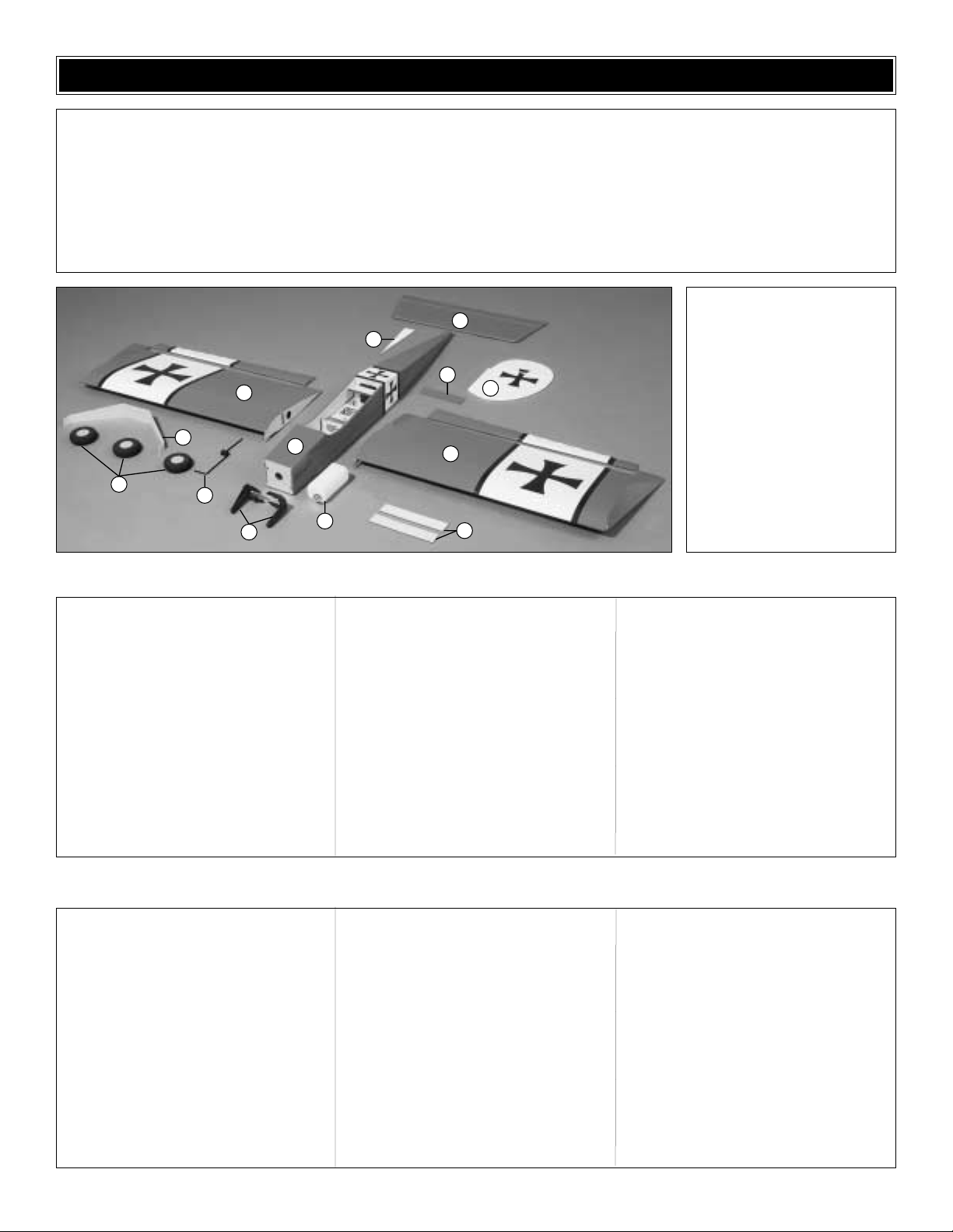
1 Wing with Aileron
2 Fuselage
3 Stabilizer and Elevator
4 Fin and Rudder
5 Wheels
6 Main Gear
7 Nose Gear
8 Engine Mount
9 Fuel Tank and Hardware
10 Wing Joiners
11 Wing Bolt Plate
12 Small Ventral Fin
Kit Contents
(Photographed)
.40 Size Kit Contents (Not Photographed)
Before starting to build, use the Kit Contents list to take an inventory of your kit to make sure it is complete and inspect
the parts to make sure they are of acceptable quality. If any parts are missing or are not of acceptable quality, or if you
need assistance with assembly, contact Great Planes Product Support. When reporting defective or missing parts, use
the part names exactly as they are written in the Kit Contents list on this page.
Great Planes Product Support:
Phone: (217) 398-8970
Fax: (217) 398-7721
E-mail: airsupport@greatplanes.com
KIT CONTENTS
(2) 1/4-20 Blind nuts (pre-installed in fuse)
(2) 24" Grey plastic outer pushrod tube
(pre-installed in fuse)
(2) 11-3/4" Grey plastic outer pushrod
tube (throttle, nose gear)
(2) 12" 074 Wire threaded one end
(ailerons)
(4) 36" 074 Wire threaded one end
(elevator, r udder, throttle, nose gear)
(5) Nylon clevis (rudder, elevator,
ailerons, throttle)
(4) Faslink (rudder, elevator, ailerons)
(2) Nylon 1/4 - 20 wing bolts
(4) Large nylon control horn (aileron,
rudder, elevator)
(1) 2" x 9" Hinge material
(6) Silicone clevis keepers (rudder,
elevator, ailerons, throttle)
(4) 4-40 x 3/4" Socket head cap screw
(engine to engine mount)
(4) # 4 Washers (engine to engine mount)
(4) 6-32 x 1/2" Socket head cap screw
(main gear to fuse)
(4) 6-32 x 3/4" Socket head cap screw
(engine mount to firewall)
(8) 6-32 Blind nuts (main gear, engine
mount)
(8) #6 Washers (main gear, engine mount)
(2) 5/32 x 1-1/4" Axles (main gear)
(2) 5/32" Nuts for axles (main gear)
(6) 5/32" Wheel collar (main landing
gear, nose gear, nose steer ing)
(1) Steering arm (nose gear)
(6) 6-32 x 1/4" Hex head bolt (wheel
collars)
(8) 2-56 x 1/2" Machine screws (rudder,
elevator, ailerons)
(3) Brass quick connect body (throttle,
nose gear)
(3) Nylon retainer (throttle, nose gear)
(3) 4-40 x 1/4" SHCS (throttle, nose gear)
(1) 2-1/2" Red spinner
(1) Fuel line 24"
(1) Wire tail skid
.60 Size Kit Contents (Not Photographed)
(2) 1/4-20 Blind nuts (pre-installed in fuse)
(2) 24" Grey plastic outer pushrod tube
(pre-installed in fuse)
(2) 11-3/4" Grey plastic outer pushrod
tube (throttle, nose gear)
(2) 12" 074 Wire threaded one end
(ailerons)
(4) 36" 074 Wire threaded one end
(elevator, r udder, throttle, nose gear)
(5) Nylon clevis (rudder, elevator, ailerons,
throttle)
(4) Faslink (rudder, elevator, ailerons)
(2) 1/4 - 20 Nylon wing bolt
(4) Large nylon control horn (aileron,
rudder, elevator)
(1) 2" x 9" Hinge material
(6) Silicone clevis keepers (rudder,
elevator, ailerons, throttle)
(4) 6-32 x 1" Socket head cap screw
(engine to engine mount)
(4) #6 Washers (engine to engine mount)
(4) 8-32 x 1/2" Socket head cap screw
(main gear to fuse)
(4) 8-32 x 1" Socket head cap screw
(engine mount to firewall)
(8) 8-32 Blind nuts (main gear, engine
mount)
(8) #8 Washers (main gear, engine mount)
(2) 5/32 x 1-1/4 axles (main gear)
(2) 5/32 Nuts (main gear axles)
(6) 5/32" Wheel collar (main landing gear,
nose, nose steering)
(1) Steering arm
(6) 6-32 x 1/4" Hex head bolt (wheel
collars)
(8) 2-56 x 1/2" machine screws (rudder,
elevator, ailerons)
(3) Brass quick connect body (throttle,
nose gear)
(3) Nylon retainer (throttle, nose gear)
(3) 4-40 x 1/4" SHCS (throttle, nose gear)
(1) 3" red spinner
(1) Fuel line 24"
(1) Wire tail skid
3
12
11
1
6
5
7
8
2
9
4
1
10
Page 6
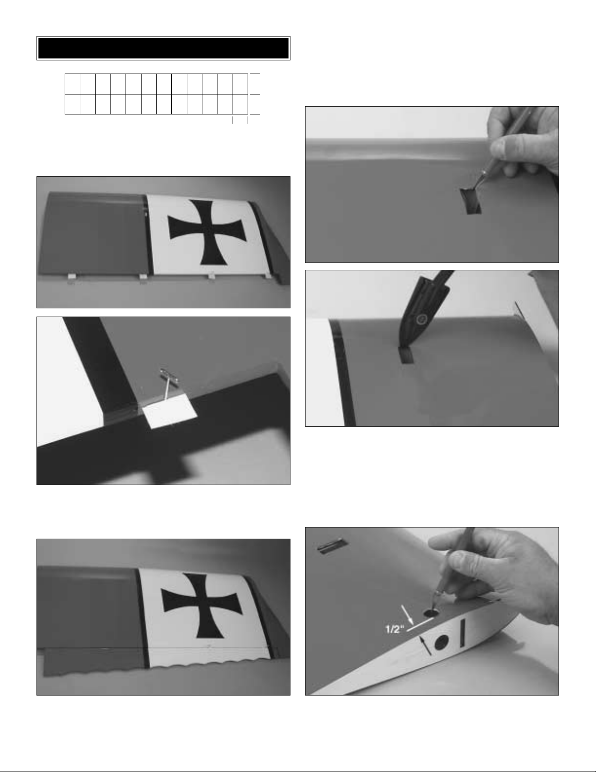
❏ 1. From the 2" x 9" [50mm x 230mm] hinge material, cut
out 16 hinges, 3/4" x 1" each [19mm x 25mm].
❏ ❏ 2. Inser t a T-pin through the center of 4 hinges.Tr ial
fit the 4 hinges into the right wing panel, making sure the
T-pin is flush against the wing.
❏ ❏ 3.T est fit the right aileron to the right wing.The aileron
should be tight against the T-pins, with no more than a 1/32"
gap at any point. When satisfied with the fit, remove the
T-pins and attach the aileron by applying 6 drops of thin CA
to each side of each hinge.After the glue has cured, flex the
aileron back and forth a few times to loosen up the hinges.
Pull on the aileron to make sure that the aileron is firmly
attached to the wing.
❏ ❏ 4. Using the photo as a guideline, locate the servo ba y
in the bottom of the right wing panel. Cut the MonoKote
1/16" to the inside of the edges of the servo tray. Using a
MonoKote Covering Iron or Trim Tool, iron the edges down
into the servo tray. NOTE: It is impor tant that you securely
iron down the edges to avoid the possibility of the covering
“flapping” and peeling off.
❏ ❏ 5. Using a dime for size reference and a hobby knife,
cut a hole in the BOTTOM of the wing parallel to the hole in
the root rib and 1/2" from the root rib.
1"
1"
3/4"
WING ASSEMBLY & INSTALLATION
6
Page 7
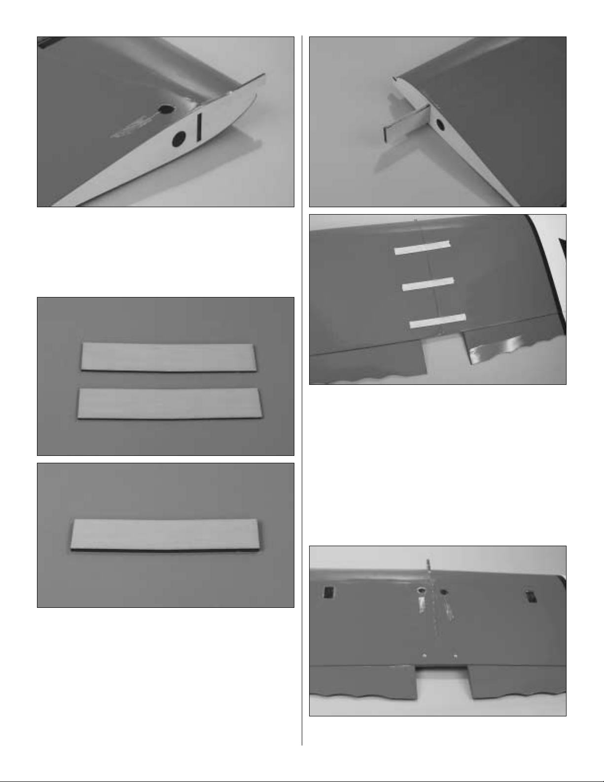
❏ ❏ 6.T aped to the inside of the root rib is a fine string.This
is used to ease installation of the aileron servo lead. Untape
the string from the root rib, pull the end through the hole you
just cut and tape the string to the underside of the wing.
❏ 7. Repeat steps 2-6 for the left wing.
❏ 8. Select the two wing joiners. Being sure to align the
angled sides, epoxy them together with 6-minute Epoxy. Do
not disturb for 1/2 hour or until the epoxy is fully cured.
❏ 9. Test fit the joiner into the right wing panel up to its
center, using no glue. Note that the pointed side of the V
shaped joiner points toward the hole you cut in step 5.Test
fit the left wing panel onto the joiner as well.Repeat until you
can comfortably join the wings.NOTE: If the wing panels do
not align (have more than a 1/16" gap on either the top or
bottom side of the wing), carefully sand the joiners to fit.
❏ 10.Coat the right half of the joiner and the right wing root
rib with 30-minute epoxy. Slide the joiner into the right wing.
Coat the left root rib and joiner half with epoxy and slide the
wing halves together. Tape the panels together, top and
bottom, with masking tape and do not disturb overnight.
NOTE:Wipe off any excess epo xy.Alcohol will help clean up
any partially cured epoxy.
❏ 11.Locate the two holes, for the wing bolts, at the trailing
edge of the bottom of the wing and cut the covering away.
7
Page 8
❏ 12. Turn the wing right side up. Position the MonoKote-
covered wing bolt plate centered on the wing and flush with its
trailing edge. Draw a line around the bolt plate. Remove the
bolt plate. Using a hobby knife and being careful to cut ONLY
the covering, cut 1/8" inside the lines you just drew and remo ve
the covering where the wing bolt plate will go.Using medium
CA, glue the non-covered side of the bolt plate to the wing.
❏ 13. Turn the wing upside-down. Using the hole through
the bottom of the wing as a guide, drill two 1/4" [6 mm] holes
through the wing.
❏ 14. Using the two 1/4"x20 nylon wing bolts and the
built-in leading edge tab, mount the wing to the fuselage.
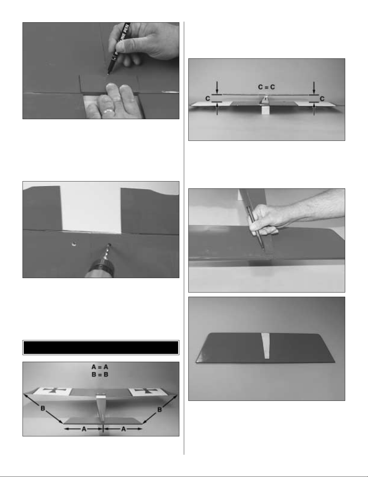
❏ 1. Remove the elevators from the stabilizer (there is only
tape holding them in place). Lay the plane upside down and
place the horizontal stabilizer into position. Check the
alignment as shown in the photo.Note: The plane is shown
right side up in the photo.Yours should be inverted.
❏ 2. Stand back 8 to 10 feet [2.5 to 3 meters] and view the
model from the front and rear.The stabilizer tips should be
equally spaced above the wing tips. If not, lightly sand the
high side of the stabilizer saddle to correct the problem.
Work slowly and check the alignment often.
❏ 3.When the alignment looks good, mark the outline of the
fuselage onto the top of the stabilizer. Remove the stabilizer
and trim the covering about 1/16" [2 mm] inside of the lines,
being very careful not to cut into the underlying wood. Note:
Use a new knife blade to insure virtually no pressure is
required to cut through the covering.Re-check your alignment
and glue the stabilizer to the fuselage with 6-minute epoxy.
INST ALL THE T AIL COMPONENTS
8
Page 9

How to cut covering from balsa.
Use a soldering iron to cut the covering from the stab.The
tip of the soldering iron doesn't have to be sharp, but a fine
tip does work best. Allow the iron to heat fully. Use a
straightedge to guide the soldering iron at a rate that will just
melt the covering and not burn into the wood.The hotter the
soldering iron, the faster it must trav el to melt a fine cut.Peel
off the covering (see the photo at step 11).
❏ 4. Remove a 1/4" strip of covering from the center of the
underside of the stab.Glue the small ventral fin in place with
medium CA.
❏ 5.Aligning the end of the skid with the trailing edge of the
ventral fin, push the tail skid into the ventral fin. Cut the
covering along either side of the tail skid and remove it.Glue
the tail skid in place with medium CA.
❏ 6. Cut the covering out of the slot on the top of the fuse.
Test fit the fin in the slot in the fuselage. When you are
satisfied with the fit, mark a line on both sides of the fin
where the top of the fuselage contacts the fin. Trim the
covering about 1/16" [2 mm] inside of the lines.
9
Page 10

❏ 7.When you are satisfied with the fit, use 6-minute epoxy
to glue the fin in position. Check the alignment of the fin to
the stabilizer with a triangle, then secure it in position with
masking tape until the epoxy has cured. Double-check the
alignment of the fin with the stabilizer while the epoxy cures.
❏ 8. Install the hinges in the stabilizer and elevator. Glue
the hinges in place the same way you did with the ailerons
on page 6, steps 1 – 3.Repeat this procedure for the rudder.
❏ 1. Slide the two 12" gray pushrod tubes through the
firewall and the corresponding holes in the second former,
leaving 1/8" [3 mm] of each of the tubes protruding from the
front of the firewall. Glue the pushrod tubes to the firewall
with thin CA.
❏ 2. Assemble the tank as shown in the sketch. Note: Make
sure the aluminum tubes are positioned as shown in the photo.
❏ 3. Fit the tank into the fuse.
❏ 4. Glue the 3/4" x 3/4" x 3/4" [19mm x 19mm x 19mm]
balsa block to the fuse bottom at the back of the tank.
TANK INSTALLATION
10
Pressure T ap
to Muffler
Silicone
Slide Into
Firewall
Firewall
Fuel Pipe
Fuel Clunk
To Needle Valve
Fuel Line
Balsa Block
Page 11

❏ 1. Cut the “spreader bar” from each engine mount half.
Carefully trim any extra material left by the spreader from
each mount half.The surfaces where the spreader bars were
attached must be smooth to allow the mount halves to fit
together.Trim the flashing off any rough edges if necessary.
Use this table for the following 4 steps:
❏ 2. Locate the washers and socket head screws for your
model size in the chart above.Use these bolts and washers
to attach the engine mount to the firewall. Position the
engine on the engine mount. Adjust the width of the mount
as needed for your engine.Tighten the bolts.
❏ 3. Position the front of your engine's thrust washer the
distance from the firewall listed in the table for your model.
❏ 4. Using the bit size called for in the table, drill the four
mounting holes for the engine into the engine mount. After
the holes have been drilled, tap as listed in the table. The
Great Planes Dead Center™ (GPMR8130) Engine Mount
Hole Locator works really well for this task.
ENGINE INSTALLATION
11
.40 Size .60 Size
Mount to firewall:Washers #6 #8
Mount to firewall: Bolts 6-32 x 3/4
" 8-32 x 1"
Thrust washer to firewall 4-3/4" [120mm] 6" [150mm]
Engine mount drill #43 [2.4mm] #36 [2.8mm]
Engine mount tap 4-40 6-32
Engine to mount: Washers #4 #6
Engine to mount: Bolts 4-40 x 3/4
" 6-32 x 1"
Specific Measurements
and Hardware Usages
Page 12

❏ 5. Install the engine with four washers and four socket
head screws of the size listed in the table.
❏ 1.Locate the four blind nuts in the bottom of the fuse.Cut
the covering from the inside of the holes.
❏ 2. Mount the aluminum landing gear to the fuse with the
four washers and four socket head screws of the size listed
for your model.
❏ 3. Locate the wire nose gear, plastic steering arm, two
5/32" [4mm] wheel collars and two 6-32 x 1/4" [6mm] socket
head screws. Place one wheel collar into the center of the
steering arm and hold it in place with one screw. Insert the
second screw into the remaining wheel collar. Place the
steering arm onto the wire nose wheel wire and inser t the
nose gear into the landing gear mount holes of the engine
mount. The steering ar m should line up with the hole in the
firewall for the steering pushrod.Place the other wheel collar
on the top of the wire, above the top of the engine mount.
Tighten the screws.This will hold the wire in place. Note: It
might be necessary to enlarge the hole in the engine mount
slightly to fit the nose gear.
❏ 4. Locate two 5/32" [4mm] wheel collars and two 6-32 x
1/4" [6mm] socket head screws. Put the screws in the wheel
collars. Slide one collar onto the nose wheel axle, then the
nose wheel and then the remaining collar. File a flat spot on
the nose gear wire where the outside wheel collar will be.
Tighten the screws to hold the wheel on the center of the axle.
MOUNT THE LANDING GEAR
12
.40 Size .60 Size
Gear mounting washers #6 #8
Gear mounting bolts 6-32 x 3/4
" 8-32 x 1"
Specific Measurements
and Hardware Usages
Page 13

❏ 5. Mount the two 5/32 axles with the two axle nuts to the
main gear.
❏ 6. Mount the main wheels to the axles with the 5/32"
[4mm] wheel collars. Using a Moto-Tool®and cut-off wheel,
cut the axles off flush with the wheel collar.
❏ 1. Cut away the covering where the pushrod tubes exit
the right side and top of the fuselage. Screw the nylon
clevises 20 turns onto the 36" pushrods. Place a silicone
retainer over each of the clevises. Holding the clevis end,
slide the two pushrods into the fuse through the openings
you just trimmed.
❏ 2. Use the pushrods to set the location for the control
horns. Hold the horn in position and mark the location of the
mounting holes. Dr ill 3/32" [2.4mm] mounting holes through
the marks. Attach the horns using #2 x 1/2" [13mm] screws
and nylon nut plates.Do not over-tighten the screws, as this
may crush the underlying balsa. Attach the clevis to the
control horns using the second hole in from the outside and
slip the silicone retainer into place on the clevis.
Correct Incorrect
RADIO INSTALLATION
13
Page 14

❏ 3. Use the following sequence for mounting the servos
into the servo tray:
❏ A. Install rubber grommets and brass eyelets in
the servos.
❏ B. Test fit the servos in the tray.
❏ C. Mark servo hole locations on the tray, then drill
1/16" [1.5mm] pilot holes through each mark.Harden
the holes with a drop of thin CA through each hole.
❏ D. Referencing the photo above for orientation,
mount the servos with the screws provided with your
radio system.
❏ 4. Following the manufacturer's recommendations, hook
up the three servos, the receiver, switch and battery as
shown in the photograph. Wrap the receiver and battery in
1/4" foam, then hold them in place by gluing small balsa
sticks (not included) above them.We added a Great Planes
Switch Mount and Charge Jack (GPMM1000, not included)
for conv enience and ease of use at the field, installed on the
left side of the fuselage, away from the exhaust.
❏ 5. Turn on your transmitter and receiver and position the
aileron, rudder, elevator and throttle trims and throttle stick
on your transmitter to the center. (This is called “centering”
the servos and will allow you to place the servo horns on the
servos in a neutral position.) Note: The servo arms have
been painted to make them show up better in the photos.
Prepare the servo arms as shown in the photo.You will need
to cut excess arms off the servo horns supplied with your
radio system. This is perfectly normal, as the multi-arm
servo horns are provided for just such purposes. Note that
the rudder servo uses a 2-armed hor n.
❏ 6.Connect the brass screw lock pushrod connectors with
the nylon retainers to the throttle and nose-gear arm of the
servo horns as shown. Note: The size and shape of servo
horns varies from manufacturer to manufacturer. The
sketches and photos show a typical radio installation with
standard horns. All standard ser vos should fit the Big Stik
with only minor modifications.
❏ 7. Mark the elevator pushrod where it crosses the servo
arm.Enlarge the servo horn holes with a 5/64" [2mm] drill bit.
14
FasLink
Servo Horn
2-56 (.074") Pushrod Wire
Page 15

❏ 8. Make a 90-degree bend in the pushrod on your mark,
then insert it through the enlarged hole in the servo arm.Cut
off the excess wire 3/8" [9.5mm] abov e the bend.Secure the
wire in place with a nylon FasLink.
❏ 9. Follow the same steps for the rudder servo. Remember
you used the two-arm type control arm on the servo in step 5.
Attach the rudder pushrod to the inside arm. You will attach
the nose wheel to the outside arm later.
❏ 10. Screw a clevis 20 turns onto a 36" pushrod. Slide the
pushrod into the throttle pushrod tube. Note: Depending on
your engine choice it might be necessary to bend the pushrod.
❏ 12.Connect the pushrod to the brass screw lock pushrod
connector on the throttle servo.Trim the extra wire off behind
the servo.
❏ 13. Slide the remainder of the throttle pushrod into the
steering pushrod tube. Bend the servo end of the pushrod
so that it does not touch the former in front of the servos.
Connect the pushrod to the brass screw lock pushrod
connector on the rudder servo.
❏ 14. Use the last brass screw lock pushrod connector to
attach the pushrod to the steering arm. Adjust the nose
wheel and tighten the cap screw. Minor adjustments to the
steering can be done at either the servo or the nose wheel
by adjusting the wire position with the screw lock pushrod
connectors. Cut the excess pushrod off in front of the
steering arm.
15
Page 16

❏ 15. Use the following sequence for mounting the servos
into the wings:
❏ A.Test fit the servos in the tray in each half of the wing.
❏ B. Mark servo hole locations on the tray, then drill
1/16" [1.5mm] pilot holes through each mark.
❏ C. Pull the string out of the ser vo opening and tie it
to the servo lead. Pull the lead through the wing.
❏ D.Mount the servos in both sides of the wing with the
screws provided with your radio system. Notice the
orientation when installing.
❏ E. Slide a silicone retainer over both servo leads so
that they won’t fall back into the wing.
❏ 16. Install the aileron nylon control horn in line with the
servo arm. Hold the horn in position and mark the location
of the mounting holes. Drill 3/32" [2.4mm] mounting holes
through the marks. Wick two to three drops of thin CA into
the holes to harden the underlying balsa, then re-drill the
holes. Attach the hor ns using #2 x 1/2" Screws and Nylon
Nut Plates. Do not overtighten the screws, crushing the
underlying balsa.
❏ 17. Center the aileron trim and aileron servo with the
transmitter and receiver on. Mark the pushrod where it
crosses the servo arm. Enlarge the servo horn hole with a
5/64" [2mm] drill bit.
❏ 18. Screw a clevis and the silicone retainer onto the
pushrod. Make a 90-degree bend in the pushrod on your
mark, then insert it through the enlarged hole in the ser vo
arm. Cut off the excess wire 3/8" [9.5mm] above the bend.
Secure the wire in place with a nylon FasLink.
❏ 1. Install the back plate, prop and prop washer onto the
engine crankshaft.Tighten the nut to hold everything in place.
❏ 2. Screw the spinner onto the backplate.
❏ 3. If you have not installed your muffler, do so now.If you
already have installed it just leave it in place.
❏ 4.Connect the lower line from the tank to the fuel inlet on
your engine. Connect the upper line from the tank to the
pressure outlet of your engine.
❏ 1. Turn on the transmitter and receiver and center the
trims. If necessary, remove the servo arms from the servos
and reposition them so they are centered. Reinstall the
screws that hold on the servo arms.
❏ 2. With the transmitter and receiver still on, check all the
control surfaces to see if they are centered.If necessary, adjust
the clevises on the pushrods to center the control surfaces.
Check the Control Directions
GET THE MODEL READY TO FLY
PROP SPINNER & FUEL LINE
INSTALLATION
16
Page 17

❏ 3. Make certain that the control surfaces and the
carburetor respond in the correct direction as shown in the
diagram.If any of the controls respond in the wrong direction,
use the servo reversing in the transmitter to reverse the
servos connected to those controls. Be cer tain the control
surfaces have remained centered. Adjust if necessary.
Use a Great Planes AccuThrow (or a ruler) to accurately
measure and set the control throw of each control surface
as indicated in the chart that follows. If your radio does not
have dual rates, we recommend setting the throws at the
lowrate setting.
NOTE: The throws are measured at the widest part of the
elevators, rudder and ailerons.
At this stage the model should be in ready-to-fly condition
with all of the systems in place including the engine, landing
gear, covering and paint and the radio system.
More than any other factor, the C.G. (balance point) can
have the greatest effect on how a model flies and may
determine whether or not your first flight will be
successful. If you value this model and wish to enjoy it for
many flights, DO NOT OVERLOOK THIS IMPORTANT
PROCEDURE. A model that is not proper ly balanced will
be unstable and possibly unflyable.
Balance the Model
IMPORTANT:The Big Stik ARF has been extensively flo wn
and tested to arrive at the throws at which it flies best.Flying
your model at these throws will provide y ou with the greatest
chance for successful first flights.If, after you have become
accustomed to the way the Big Stik ARF flies, y ou would lik e
to change the throws to suit your taste, that is fine.However,
too much control throw could make the model difficult to
control, so remember, “more is not always better.”
These are the recommend control surface throws for the
Big Stik .60:
High Rate Low Rate
ELEVATOR: 7/8" [22mm] up 5/8" [16mm] up
7/8" [22mm] down 5/8" [16mm] down
RUDDER: 1-1/2" [38mm] right 1-1/4" [32mm] right
1-1/2" [38mm] left 1-1/4" [32mm] left
AILERONS: 1" [25mm] up 3/4" [19mm] up
1" [25mm] down 3/4" [19mm] down
These are the recommend control surface throws for the
Big Stik .40:
High Rate Low Rate
ELEVATOR: 3/4" [19mm] up 5/8" [16mm] up
3/4" [19mm] down 5/8" [16mm] down
RUDDER: 1-3/8" [41mm] right 1" [25mm] right
1-3/8" [41mm] left 1" [25mm] left
AILERONS: 7/8" [22mm] up 5/8" [16mm] up
7/8" [22mm] down 5/8" [16mm] down
Set the Control Throws
4-CHANNEL RADIO SETUP
17
C.G. .40 Size .60 Size
Starting Point 3-3/4
" [95mm] 4" [102mm]
Total Range 3-1/4" to 4" 3-3/4" to 4-1/2"
[82mm to 102mm] [95mm to 115mm]
(STANDARD MODE 2)
ELEVATOR MOVES UP
4-CHANNEL
TRANSMITTER
RIGHT AILERON MOVES UP
LEFT AILERON MOVES DOWN
4-CHANNEL
TRANSMITTER
RUDDER MOVES RIGHT
NOSE WHEEL TURNS RIGHT
4-CHANNEL
TRANSMITTER
CARBURETOR WIDE OPEN
4-CHANNEL
TRANSMITTER
Page 18

❏ 1. Use a felt-tip pen or 1/8"-wide tape to accurately mark
the C.G. on the bottom of the wing on both sides of the
fuselage.The C.G.is located as indicated in the table above,
measured back from the leading edge of the wing.
❏ 2.With the wing attached to the fuselage, all parts of the
model installed (ready to fly) and an empty fuel tank, place
the model right side up on a Great Planes CG Machine, or
lift it right side up at the balance point you marked.
❏ 3. If the tail drops, the model is “tail heavy” and the
battery pack and/or receiver must be shifted forward or
weight must be added to the nose to balance. If the nose
drops, the model is “nose heavy” and the battery pack
and/or receiver must be shifted aft or weight must be added
to the tail to balance. If possible, relocate the battery pack
and receiver to minimize or eliminate any additional ballast
required. If additional weight is required, nose weight may
be easily added by using a “spinner weight”(GPMQ4645 for
the 1 oz. weight, or GPMQ4646 for the 2 oz. weight). If
spinner weight is not practical or is not enough, use Great
Planes (GPMQ4485) “stick-on” lead. A good place to add
stick-on nose weight is to the firewall (don't attach weight to
the cowl–it is not intended to support weight). Begin by
placing incrementally increasing amounts of weight on the
top of the fuse over the firewall until the model balances.
Once you have determined the amount of weight required, it
can be permanently attached. If required, tail weight may be
added by cutting open the bottom of the fuse and gluing it
permanently inside.
Note: Do not rely upon the adhesive on the back of the lead
weight to permanently hold it in place. Over time, fuel and
exhaust residue may soften the adhesive and cause the
weight to fall off .Use #2 sheet metal screws, RTV silicone or
epoxy to permanently hold the weight in place.
❏ 4. IMPORTANT: If you found it necessary to add any
weight, recheck the C.G.after the weight has been installed.
❏ 1. With the wing level, have an assistant help you lift the
model by the engine propeller shaft and the top of the
rudder.Do this several times.
❏ 2.If one wing always drops when you lift the model, it means
that side is heavy. Balance the airplane by adding weight to the
other wing tip. An airplane that has been laterally balanced
will track better in loops and other maneuvers.
No matter if you fly at an AMA sanctioned R/C club site or if
you fly somewhere on your own, you should always have
your name, address, telephone number and AMA number
on or inside your model. It is required at all AMA R/C club
flying sites and AMA sanctioned flying events
Follow the battery charging instructions that came with your
radio control system to charge the batteries. You should
always charge your transmitter and receiver batteries the
night before you go flying and at other times as
recommended by the radio manufacturer.
NOTE: Checking the condition of your receiver battery pack
is highly recommended. All battery packs, whether it's a
trusty pack you've just taken out of another model, or a new
battery pack you just purchased, should be cycled, noting
the discharge capacity. Oftentimes, a weak battery pack can
be identified (and a valuable model saved!) by comparing its
actual capacity to its rated capacity. Refer to the instructions
and recommendations that come with your cycler. If you
don't own a battery cycler, perhaps you can have a friend
cycle your pack and note the capacity for you.
Charge the Batteries
Identify Y our Model
PREFLIGHT
Balance the Model Laterally
This is where your model should balance for your first
flights. Later, you may wish to experiment by shifting the
C.G. within the range given above to change the flying
characteristics. Moving the C.G. forward may improve the
smoothness and stability, but it may then require more
speed for takeoff and make it more difficult to slow for
landing. Moving the C.G. aft makes the model more
maneuverable, but could also cause it to become too
difficult for you to control.In any case, start at the location
we recommend and do not at any time balance your
model outside the recommended range.
3-3/4"
18
4"
Big Stik .40
Big Stik .60
Page 19

Carefully balance your propeller and spare propellers before
you fly. An unbalanced prop can be the single most
significant cause of vibration that can damage your model.
Not only will engine mounting screws and bolts loosen,
possibly with disastrous effect, but vibration may also
damage your radio receiver and battery. Vibration can also
cause your fuel to foam, which will, in turn, cause your
engine to run hot or quit.
We use a Top Flite Precision Magnetic Prop Balancer™
(TOPQ5700) in the workshop and keep a Great Planes
Fingertip Prop Balancer (GPMQ5000) in our flight box.
If the engine is new, follow the engine manufacturer's
instructions to break-in the engine. After break-in,
confirm that the engine idles reliably, transitions smoothly
and rapidly to full power and maintains full powerindefinitely. After you run the engine on the model, inspect
the model closely to make sure all screws remained tight,
the hinges are secure, the prop is secure and all pushrods
and connectors are secure.
Ground check the operational range of your r adio before the
first flight of the day. With the transmitter antenna collapsed
and the receiver and transmitter on, you should be able to
walk at least 100 feet away from the model and still have
control. Have an assistant stand by your model and, while
you work the controls, tell you what the control surfaces are
doing. Repeat this test with the engine running at various
speeds with an assistant holding the model, using hand
signals to show you what is happening. If the control
surfaces do not respond correctly, do not fly! Find and
correct the problem first.Look for loose servo connections or
broken wires, corroded wires on old servo connectors, poor
solder joints in your battery pack or a defective cell, or a
damaged receiver crystal from a previous crash.
Keep all engine fuel in a safe place, away from high heat,
sparks or flames, as fuel is very flammable. Do not smoke
near the engine or fuel; and remember that engine exhaust
gives off a great deal of deadly carbon monoxide.Therefore
do not run the engine in a closed room or garage.
Get help from an experienced pilot when learning to
operate engines.
Use safety glasses when starting or running engines.
Do not run the engine in an area of loose gravel or sand;the
propeller may throw such material in your face or eyes.
Keep your f ace and body as well as all spectators a wa y from the
plane of rotation of the propeller as you start and run the engine.
Keep these items away from the prop: loose clothing, shir t
sleeves, ties, scarfs, long hair or loose objects such as
pencils or screwdrivers that may fall out of shirt or jacket
pockets into the prop.
Use a “chicken stick” or electric starter to star t the engine.
Do not use your fingers to flip the propeller .Make certain the
glow plug clip or connector is secure so that it will not pop
off or otherwise get into the running propeller.
Make all engine adjustments from behind the rotating propeller .
The engine gets hot! Do not touch it during or right after
operation. Make sure fuel lines are in good condition so fuel
will not leak onto a hot engine, causing a fire.
To stop a glow engine, cut off the fuel supply by closing off
the fuel line or following the engine manufacturer's
recommendations. Do not use hands, fingers or any other
body part to try to stop the engine.To stop a gasoline powered
engine an on/off switch should be connected to the engine coil.
Do not throw anything into the propeller of a running engine.
Read and abide by the following Academy of Model
Aeronautics Official Safety Code:
1. I will not fly my model aircraft in sanctioned events, air
shows, or model flying demonstrations until it has been
proven to be airworthy by having been previously
successfully flight tested.
General
AMA SAFETY CODE (
EXCERPT
)
Failure to follow these safety precautions may result
in severe injury to yourself and others.
ENGINE SAFETY PRECAUTIONS
Range Check
Ground Check
Balance Propellers
19
Page 20

2. I will not fly my model aircraft higher than approximately
400 feet within 3 miles of an airport without notifying the
airpor t operator. I will give right of way to and avoid flying in
the proximity of full scale aircraft. Where necessary an
observer shall be used to supervise flying to avoid having
models fly in the proximity of full scale aircraft.
3. Where established, I will abide by the safety rules for the
flying site I use and I will not willfully and deliberately fly my
models in a careless, reckless and/or dangerous manner.
7. I will not fly my model unless it is identified with my
name and address or AMA number, on or in the model.
9. I will not operate models with pyrotechnics (any device
that explodes, burns, or propels a projectile of any kind).
1. I will have completed a successful radio equipment
ground check before the first flight of a ne w or repaired model.
2. I will not fly my model aircraft in the presence of
spectators until I become a qualified flier, unless assisted b y
an experienced helper.
3. I will perform my initial turn after takeoff away from the
pit or spectator areas and I will not thereafter fly over pit or
spectator areas, unless beyond my control.
4. I will operate my model using only radio control
frequencies currently allowed by the Federal
Communications Commission.
❏ 1. Fuelproof all areas exposed to fuel or exhaust residue
such as the firewall, wing saddle area, etc.
❏ 2. Check the C.G. according to the measurements
provided in the manual.
❏ 3. Be certain the battery and receiver are securely
mounted in the fuse. Simply stuffing them into place with
foam rubber is not sufficient.
❏ 4. Extend your receiver antenna and make sure it has a
strain relief inside the fuselage to keep tension off the solder
joint inside the receiver.
❏ 5. Balance your model
laterally
as explained in
the instructions.
❏ 6. Use threadlocking compound to secure critical
fasteners such as the set screws that hold the wheel axles
to the struts, screws that hold the carburetor arm (if
applicable), screw-lock pushrod connectors, etc.
❏ 7. Add a drop of oil to the axles so the wheels will turn freely.
❏ 8. Make sure all hinges are securely glued in place.
❏ 9. Reinforce holes for wood screws with thin CA where
appropriate (servo mounting screws, cowl mounting
screws, etc.).
❏ 10. Confirm that all controls operate in the correct
direction and the throws are set up according to the manual.
❏ 11. Make sure there are silicone retainers on all the
clevises and that all servo arms are secured to the servos
with the screws included with your radio.
❏ 12. Secure connections between servo wires and Y-
connectors or servo extensions and the connection between
your battery pack and the on/off switch with vinyl tape, heat
shrink tubing or special clips suitable for that purpose.
❏ 13. Make sure any servo extension cords you may have
used do not interfere with other systems (servo arms,
pushrods, etc.).
❏ 14.Secure the pressure tap (if used) to the muffler with high
temp RTV silicone, thread locking compound or J.B. Weld.
❏ 15. Make sure the fuel lines are connected and are
not kinked.
❏ 16. Use an incidence meter to check the wing for twists
and attempt to correct before flying.
❏ 17. Balance your propeller (and spare propellers).
❏ 18. Tighten the propeller nut and spinner.
❏ 19. Place your name, address, AMA number and
telephone number on or inside your model.
❏ 20. Cycle your receiver battery pack (if necessary) and
make sure it is fully charged.
❏ 21. If you wish to photograph your model, do so before
your first flight.
❏ 22.Range check your radio when you get to the flying field.
During the last few moments of preparation your mind
may be elsewhere anticipating the excitement of the first
flight. Because of this, you may be more likely to overlook
certain checks and procedures that should be performed
before the model is flown.To help avoid this, a checklist is
provided to make sure these important areas are not
overlooked. Many are covered in the instruction manual,
so where appropriate, refer to the manual for complete
instructions. Be sure to check the items as off they are
completed (that's why it's called a check list!).
CHECKLIST
Radio Control
20
Page 21

The Big Stik ARF is a great-flying model that flies smoothly
and predictably. The Big Stik ARF does not, however,
possess the self-recovery characteristics of a primary R/C
trainer and should be flown only be experienced R/C pilots.
Before you get ready to tak e off, see how the model handles
on the ground by doing a few practice runs at low speeds
on the runway. If necessar y, adjust the nose wheel so the
model will roll straight down the runway. If you need to calm
your nerves before the maiden flight, shut the engine down
and bring the model back into the pits.Top off the fuel, then
check all fasteners and control linkages for peace of mind.
Remember to take off into the wind. When you're ready,
point the model straight down the runway, then gradually
advance the throttle. Gain as much speed as your runway
and flying site will practically allow before gently applying up
elevator, lifting the model into the air. At this moment it is
likely that you will need to apply more right rudder to
counteract engine torque. Be smooth on the elevator stick,
allowing the model to establish a gentle climb to a safe
altitude before turning into the traffic pattern.
For reassurance and to keep an eye on other traffic, it is a
good idea to have an assistant on the flight line with you.Tell
him to remind you to throttle back once the plane gets to a
comfortable altitude.While full throttle is usually desirable for
takeoff, most models fly more smoothly at reduced speeds.
Take it easy with the Big Stik ARF for the first few flights,
gradually getting acquainted with it as you gain confidence.
Adjust the trims to maintain straight and level flight. After
flying around for a while and while still at a safe altitude with
plenty of fuel, practice slow flight and execute practice
landing approaches by reducing the throttle to see how the
model handles at slower speeds.Add power to see how she
climbs as well. Continue to fly around, executing various
maneuvers and making mental notes (or having your
assistant write them down) of what trim or C.G. changes
may be required to fine tune the model so it flies the wa y you
like. Mind your fuel level, but use this first flight to become
familiar with your model before landing.
To initiate a landing approach, lower the throttle while on the
downwind leg. Allow the nose of the model to pitch
downward to gradually bleed off altitude. Continue to lose
altitude, but maintain airspeed by k eeping the nose down as
you turn onto the crosswind leg.Make your final turn toward
the runway (into the wind) keeping the nose down to
maintain airspeed and control. Level the attitude when the
model reaches the runway threshold, modulating the throttle
as necessary to maintain your glide path and airspeed. If
you are going to overshoot, smoothly advance the throttle
(always ready on the right rudder to counteract torque) and
climb out to make another attempt. When you're ready to
make your landing flare and the model is a foot or so off the
deck, smoothly increase up elevator until it gently touches
down. Once the model is on the runway and has lost flying
speed, hold up elevator to place the tail on the ground,
regaining tail wheel control.
One final note about flying your model. Have a goal or flight
plan in mind for every flight. This can be learning a new
maneuver(s), improving a maneuver(s) y ou already kno w, or
learning how the model behaves in certain conditions (such
as on high or low rates). This is not necessarily to improve
your skills (
though it is never a bad idea!
), but more
importantly so you do not surprise yourself by impulsively
attempting a maneuver and suddenly finding that you'v e run
out of time, altitude or airspeed. Every maneuver should be
deliberate, not impulsive.For example, if you're going to do
a loop, check your altitude, mind the wind direction
(anticipating rudder corrections that will be required to
maintain heading), remember to throttle back at the top and
make certain you are on the desired rates (high/low rates).
A flight plan greatly reduces the chances of crashing your
model just because of poor planning and impulsive moves.
Remember to think.
Have a ball! But always stay in control
and fly in a safe manner.
GOOD LUCK AND GREAT FLYING!
Landing
Flight
Takeoff
CAUTION (THIS APPLIES TO ALL R/C AIRPLANES): If,
while flying, you notice any unusual sounds, such as a
low-pitched “buzz,” this may indicate control surface
flutter
. Because flutter can quickly destroy components of
your airplane, any time you detect flutter you must
immediately cut the throttle and land the airplane! Check
all servo grommets for deterioration (this may indicate
which surface fluttered) and make sure all pushrod
linkages are secure and free of play. If the control surface
fluttered once, it probably will flutter again under similar
circumstances unless you can eliminate the free-play or
flexing in the linkages. Here are some things which can
cause flutter: Excessive hinge gap; Not mounting control
horns solidly; Poor fit of clevis pin in horn; Side-play of
pushrod in guide tube caused by tight bends;Poor fit of Zbend in servo arm; Insufficient glue used when gluing in
the elevator joiner wire; Excessive
play
or
backlash
in
servo gears; and Insecure servo mounting.
FLYING
21
Page 22

22
OTHER PLANES FROM GREAT PLANES
SpaceWalker ARF
GPMA1300
Based on Jesse Anglin’s ’86 tribute to ’30s
homebuilts, the SpaceWalker takes only a few
hours to assemble. It has a strong, wood frame;
welded, steel landing gear;side plates; ABS wheel
pants;windshield; and a cowl color-matched to the
MonoKote covering. Smooth in flight, it blends the
muscle of dual aileron servos with the aerobatic
potential of a symmetrical airfoil.
Note: Pilot figure not included.
Piper J-3 Cub ARF
GPMA1310
This sport-scale model is all-wood, impressively
detailed, and flight-ready in as little as 15-20
hours! Surrounding the CAD-engineered
framework is real woven Coverite™21st
Century®fabric. With its dual aileron ser vos the
Cub maneuvers well. It also lands gently and
includes a prepainted fiberglass cowl, replica
cylinder heads, adjustable engine mount and
Great Planes-brand hardware.
Note: Pilot figure not included.
A T -6 T e xan ARF
GPMA1245
Enjoy smooth flight and easy aerobatics with
this kit-quality ARF. Precision-molded, painted
parts include a glass-reinforced cowl. Plus, the
AT-6 offers the strength of wood...the
dependability of Great Planes hardware...and
the fine finish of Top Flite MonoKote film. Fixed
landing gear is supplied, though wheel wells
and mounting rails are built-in for retracts.
Note: Pilot figures not included.
Giles G-202
GPMA1315
Designed to convince “kitters”that ARFs can be
outstanding! Parts interlock for strength, and are
all-wood except for fiberglass parts factorypainted to match the preapplied MonoKote
covering. Competition mounted ser vos (2 each
for ailerons and elevators, 1 for the rudder) plus
double-beveled rudder and elevator control
surfaces open the way for wild, 3D stunts.
Note: Pilot figure not included.
Page 23

Great Planes®Pre-Built Master Caddy with APS
™
(GPMP1001)
The pre-painted, Pre-Built Master Caddy field box is flightready in less than an hour. Its design saves space while
neatly storing and organizing all necessary equipment. It
includes three top compartments, two large drawers with
dividers, and a shelf for securely holding a gallon of fuel.
Cushioned, adjustable-width cradles safely hold planes for
cleanup or repairs. Plus, the unique Auxiliary Power Station
(APS) holds all of your starting gear and detaches from the
Master Caddy for convenient starting anywhere at the field.
Great Planes®Dead Center™Engine Mount Hole
Locator (GPMR8130)
Makes perfect mount installations easy! Just position the
engine on the mount, and Dead Center’s self-centering
cone in the bolt hole.Twist the shaft, and a drill bit inside
makes a small starter hole.
Great Planes®Accu-Throw
™
Control Surface Deflection Meter
GPMR2405
One leading cause of crashes is flying an airplane with its
control throws set differently from those recommended in
the instructions. The Great Planes AccuThrow™lets you
quickly and easily measure actual throws first, so you can
make necessary corrections before you fly. Large, no-slip
rubber feet provide a firm grip on covered surfaces without
denting or marring the finish. Spring tension holds
AccuThrow’s plastic ruler steady by each control surface.
Curved to match control motions, the ruler provides exact
readings in both standard or metric measurements.
Hobbico®DC Quick Field Charger
(HCAM3000)
The Quick Field Charger recharges 9.6V transmitter and 4.8V or
6.0V receiver batteries right on the spot, using any 12V DC
input. Advanced Delta peak sensing technology automatically
switches to trickle once batteries are fully charged. Unique
voltage boost circuitry peaks transmitter NiCds even in diodeequipped radios.Includes 2.5A fuse, alligator clips on a 14" input
cord and banana plugs.2-year warranty. Connectors required.
23
OTHER ITEMS AVAILABLE FROM GREAT PLANES
Page 24

BUILDING NOTES
Kit Purchased Date: _______________________
Where Purchased:_________________________
Date Construction Started: __________________
Date Construction Finished: _________________
Finished Weight: __________________________
Date of First Flight: ________________________
FLIGHT LOG
 Loading...