

Page 1
WARRANTY
Great Planes
®
Model Manufacturing Co. guarantees this kit to be free from defects in both material and workmanship at the date of
purchase.This warranty does not cover any component parts damaged by use or modification. In no case shall Great Planes’liability
exceed the original cost of the purchased kit. Further, Great Planes reserves the right to change or modify this warranty without notice.
In that Great Planes has no control over the final assembly or material used for final assembly, no liability shall be assumed nor
accepted for any damage resulting from the use by the user of the final user-assemb led product.By the act of using the user-assembled
product, the user accepts all resulting liability.
If the buyer is not prepared to accept the liability associated with the use of this product, the buyer is advised to return this
kit immediately in new and unused condition to the place of purchase.
To make a warranty claim send the defective part or item to Hobby Services at the address below:
Hobby Services
3002 N. Apollo Dr. Suite 1
Champaign IL 61822 USA
Include a letter stating your name, return shipping address, as much contact information as possible (daytime telephone number, fax
number, e-mail address), a detailed description of the problem and a photocopy of the purchase receipt. Upon receipt of the package
the problem will be evaluated as quickly as possible.
READ THROUGH THIS MANUAL BEFORE STARTING
CONSTRUCTION. IT CONTAINS IMPORTANT WARNINGS
AND INSTRUCTIONS CONCERNING THE ASSEMBLY
AND USE OF THIS MODEL.
GPMZ0180 for GPMA1219 V1.1© Copyright 2005
Champaign, Illinois
(217) 398-8970, Ext 5
airsupport@greatplanes.com
INSTRUCTION MANUAL
Wingspan: Top Wing - 76 in [1930mm]
Bottom Wing - 63 in [1600mm]
Wing Area: Top Wing - 852 sq in [55 dm2]
Bottom Wing - 589 sq in [38 dm2]
Weight: 14–16 lb [6348 – 7255 g]
Wing Loading: 22–26 oz/sq ft [67-79 g/dm2]
Length: 59.75 in [1518mm]
Radio: 4-channel with 5 servos
Engine: .91-1.08 cu in [15-17.5cc] two-stroke,
.91-1.20 cu in [19.5-23cc] four-stroke
Page 2

INTRODUCTION ...............................................................2
IMAA..................................................................................2
SAFETY PRECAUTIONS..................................................2
ADDITIONAL ITEMS REQUIRED.....................................3
Hardware & Accessories.............................................3
Adhesives & Building Supplies....................................3
Optional Supplies & Tools ...........................................4
IMPORTANT BUILDING NOTES......................................4
INFORMATION ABOUT WORKING WITH FIBERGLASS
...4
KIT INSPECTION..............................................................5
KIT CONTENTS ................................................................5
ORDERING REPLACEMENT PARTS ..............................6
PREPARATIONS ...............................................................7
BUILD THE WINGS...........................................................7
Installing the Ailerons..................................................7
Join The Top Wing Panels...........................................8
Join The Bottom Wing Panels.....................................8
Install The Bottom Wing ..............................................9
INSTALL THE STABILIZER AND FIN ............................10
Install The Stabilizer And Elevator.............................10
Install The Fin And Rudder .......................................10
INSTALL THE MAIN LANDING GEAR...........................12
INST ALL THE ENGINE ...................................................13
Mount The Engine.....................................................13
Mount The Cowl ........................................................14
Install The Fuel T ank.................................................15
Install The Throttle Servo..........................................16
Finish Assembling The Cowl.....................................17
INSTALL THE RADIO SYSTEM ......................................18
Install The Rudder And Elevator Servos...................18
Install The Aileron Servos & Pushrods......................21
INST ALL THE TOP WING................................................22
FINISH THE FUSELAGE.................................................23
Build The Carrying Handle........................................23
Assemble The Nose Weight Box ...............................25
Finishing Touches......................................................25
Optional Flying Wire Installation................................26
Apply The Decals ......................................................29
GET THE MODEL READY TO FLY .................................30
Check the Control Directions ....................................30
Set the Control Throws..............................................30
Balance the Model (C.G.)..........................................30
Balance the Model Laterally ......................................31
PREFLIGHT.....................................................................31
Identify Your Model ....................................................31
Charge the Batteries .................................................31
Balance the Propellers..............................................32
Ground Check...........................................................32
Range Check.............................................................32
ENGINE SAFETY PRECAUTIONS.................................32
AMA SAFETY CODE (
EXCERPTS)....................................33
IMAA SAFETY CODE (EXCERPTS)...................................33
CHECK LIST ...................................................................34
FLYING ............................................................................34
Fuel Mixture Adjustments..........................................34
Take Off.....................................................................34
Flight..........................................................................35
Landing......................................................................35
The P-6E Hawk has a long and colorful history in both the
U.S.militar y and abroad.You will thoroughly enjoy the wide
range of capabilities of this plane as well as its good looks.
We think you will be pleased with its attention to detail and
flight characteristics.
For the latest technical updates or manual corrections to the
P-6E Hawk ARF, visit the Great Planes web site at
www.greatplanes.com. Open the “Airplanes” link, then
select the P-6E Hawk ARF. If there is new technical
information or changes to this model a “tech notice” box will
appear in the upper left corner of the page.
The P-6E Hawk ARF is an excellent sport-scale model and
is eligible to fly in IMAA events. The IMAA (International
Miniature Aircraft Association) is an organization that
promotes non-competitive flying of giant-scale models. If
you plan to attend an IMAA ev ent, obtain a cop y of the IMAA
Safety Code by contacting the IMAA at the address or
telephone number below, or by logging on to their web site
at www.fly-imaa.org/imaa/sanction.html.
IMAA
205 S. Hilldale Road
Salina, KS 67401
(913) 823-5569
1.Your P-6E Hawk ARF should not be considered a toy, but
rather a sophisticated, working model that functions very
much like a full-size airplane. Because of its performance
capabilities, the P-6E Hawk ARF, if not assembled and
operated correctly, could possibly cause injury to yourself or
spectators and damage to property.
2. You must assemble the model according to the
instructions. Do not alter or modify the model, as doing so
may result in an unsafe or unflyable model. In a few cases
the instructions may differ slightly from the photos.In those
instances the written instructions should be considered
as correct.
3.You must take time to build straight, true and strong.
4. You must use an R/C radio system that is in first-class
condition, and a correctly sized engine and components
(fuel tank, wheels, etc.) throughout the building process.
PRO TECT YOUR MODEL,Y OURSELF
& OTHERS...FOLLOW THESE
IMPORTANT SAFETY PRECAUTIONS
IMAA
INTRODUCTIONTABLE OF CONTENTS
2
Page 3
5.You must correctly install all R/C and other components so
that the model operates correctly on the ground and in the air .
6.You must check the operation of the model before every
flight to insure that all equipment is operating and that the
model has remained structurally sound. Be sure to check
clevises or other connectors often and replace them if they
show any signs of wear or fatigue.
7. If you are not already an experienced R/C pilot, you
should fly the model only with the help of a competent,
experienced R/C pilot.
8.While this kit has been flight tested to exceed normal use,
if the plane will be used for extremely high stress flying, such
as racing, the modeler is responsible for taking steps to
reinforce the high stress points.
9.WARNING:The cowl, landing gear covers and wing struts
included in this kit are made of fiberglass, the fibers of which
may cause eye, skin and respiratory tract irritation. Never
blow into a part to remove fiberglass dust, as the dust will
blow back into your eyes. Always wear safety goggles, a
particle mask and rubber gloves when grinding, drilling and
sanding fiberglass parts. Vacuum the parts and the work
area thoroughly after working with fiberglass parts.
Remember:Take your time and f ollo w the instructions to
end up with a well-built model that is straight and true.
If you have not flo wn this type of model bef ore, we recommend
that you get the assistance of an experienced pilot in your R/C
club for your first flights.If you’re not a member of a club, your
local hobby shop has information about clubs in your area
whose membership includes experienced pilots.
In addition to joining an R/C club, we strongly recommend y ou
join the AMA (Academy of Model Aeronautics). AMA
membership is required to fly at AMA sanctioned clubs.There
are over 2,500 AMA chartered clubs across the country.
Among other benefits, the AMA provides insurance to its
members who fly at sanctioned sites and events .Additionally,
training programs and instructors are available at AMA club
sites to help you get started the right way. Contact the AMA at
the address or toll-free phone number that follows.
Academy of Model Aeronautics
5151 East Memorial Drive
Muncie, IN 47302-9252
Tele. (800) 435-9262
Fax (765) 741-0057
Or via the Internet at:
http://www.modelaircraft.org
This is the list of hardware and accessories required to finish
the P-6E Hawk.Order numbers are provided in parentheses.
❏ Engine (refer to the engine size requirements on the
cover of the manual)
❏ 4-Channel radio
❏ (1) standard servo (throttle)
❏ (4) servos with minimum of 54 oz/in torque
(2-ailerons, 1-elevator, 1-rudder)
❏ (2) 6" [300mm] servo extensions (for aileron servos,
HCAM2701 for Futaba®)
❏ (1) Y-harness (for aileron servos, HCAM2751for Futaba)
❏ (1) minimum 1,000mAh receiver battery
❏ Propeller and spare propellers (refer to your engine
manufacturer’s recommendations)
In addition to common household tools and hobby tools, this
is the “short list” of the most important items required to build
the P-6E Hawk ARF.
Great Planes Pro™CA and Epoxy glue
are recommended.
❏ R/C foam rubber (1/4" [6mm] – HCAQ1000, or
1/2" [13mm] – HCAQ1050)
❏ 1 oz. [30g] Thin Pro CA (GPMR6002)
❏ 1 oz. [30g] Medium Pro CA+ (GPMR6008)
❏ Pro 30-minute epoxy (GPMR6047)
❏ Pro 6-minute epoxy (GPMR6045)
❏ Threadlocker
™
thread-locking cement (GPMR6060)
❏ Drill bits: 1/16" [1.6mm], 5/64" [2mm], 3/32" [2.4mm], 1/8"
[3mm], #29 or 9/64" [3.6mm], 3/16" [4.8mm], 7/32" [5.5mm]
❏ 8-32 tap
❏ 1/2" wrench
❏ Hex head wrench set
❏ 5 pkgs Stick-on segmented lead weights (GPMQ4485)
❏ #1 Hobby knife (HCAR0105)
❏ #11 Blades (5-pack, HCAR0211)
❏ Small T-pins (100, HCAR5100)
❏ R/C-56 canopy glue (JOZR5007)
❏ CA applicator tips (HCAR3780)
❏ Denatured alcohol (for epoxy cleanup)
❏ Curved-tip canopy scissors for trimming plastic parts
(HCAR0667)
Adhesives and Building Supplies
Hardware and Accessories
ADDITIONAL ITEMS REQUIRED
Note: We, as the kit manufacturer, provide you with a top
quality kit and great instructions, but ultimately the quality
of your finished model depends on how you build it;
therefore, we cannot in any way guarantee the
performance of your completed model, and no
representations are expressed or implied as to the
performance or safety of your completed model.
3
Page 4
Here is a list of optional tools mentioned in the manual that
will help you build the P-6E Hawk ARF.
❏ 2 oz. [57g] spray CA activator (GPMR6035) or
4 oz. [113g] aerosol CA activator (GPMR634)
❏ Epoxy brushes (6, GPMR8060)
❏ Mixing sticks (50, GPMR8055)
❏ Mixing cups (GPMR8056)
❏ Builder’s Triangle Set (HCAR0480)
❏ Pliers with wire cutter (HCAR0630)
❏ Robar t Super Stand II (ROBP1402)
❏ Hobbico
®
Duster™can of compressed air (HCAR5500)
❏ Masking tape (TOPR8018)
❏ Microballoons (TOPR1090)
❏ Rotary tool such as Dremel
®
❏ Rotary tool reinforced cut-off wheel (GPMR8200)
❏ Servo horn dr ill (HCAR0698)
❏ Dead Center
™
Engine Mount Hole Locator (GPMR8130)
❏ AccuThrow
™
Deflection Gauge (GPMR2405)
❏ CG Machine
™
(GPMR2400)
❏ Precision Magnetic Prop Balancer
™
(TOPQ5700)
❏ Fuel filler valve for glow fuel (GPMQ4160)
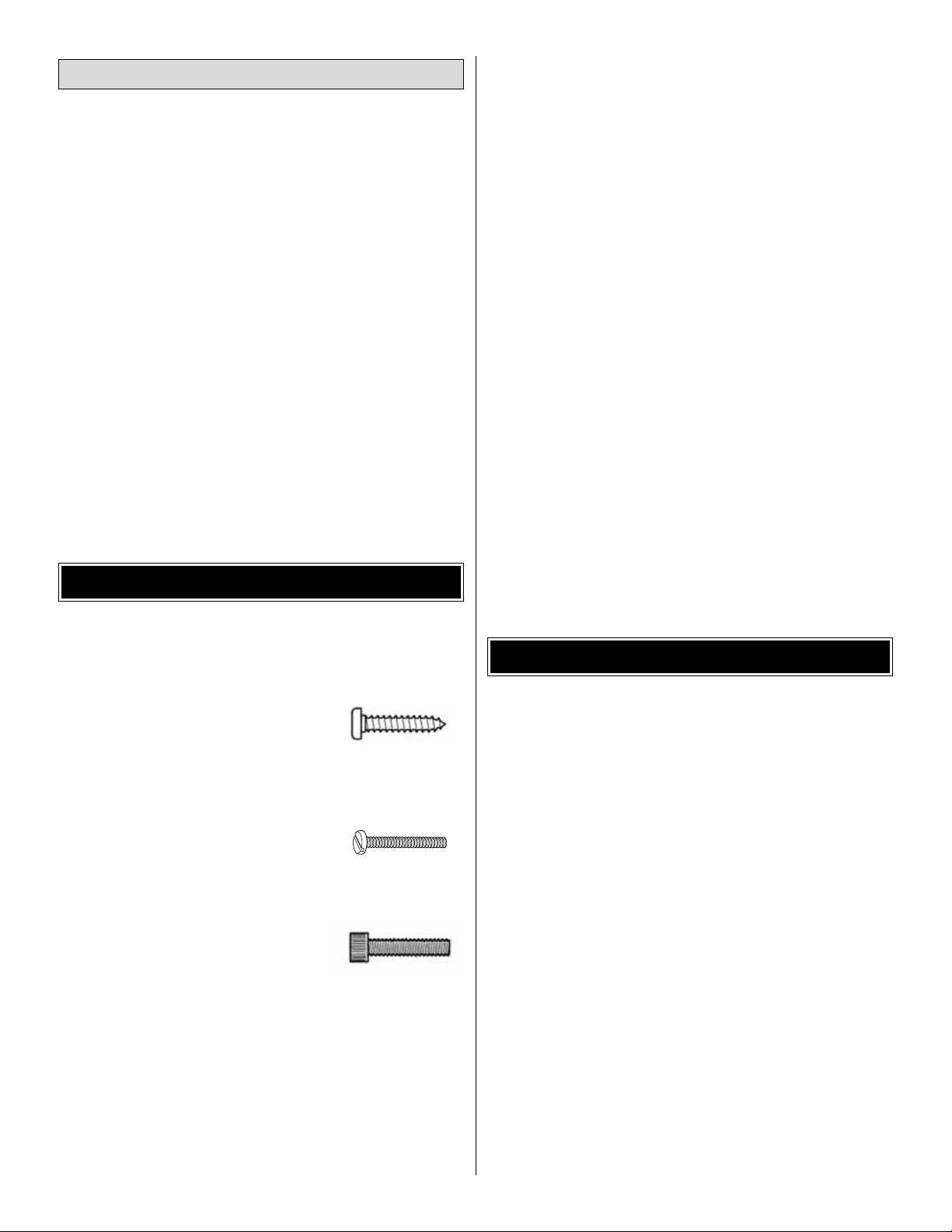
• There are two types of screws used in this kit:
Sheet metal screws are designated by a number and a
length. For example #6 x 3/4" [19mm]
This is a number six screw that is 3/4
"
[19mm] long.
Machine screws are designated by a number, threads per
inch and a length. For example 4-40 x 3/4" [19mm]
This is a number four screw that is 3/4"
[19mm] long with forty threads per inch
.
Socket head cap screwsare designated by a number , threads
per inch and a length. For example 4-40 x 3/4" [19mm]
This is a number four screw that is 3/4"
[19mm] long with forty threads per inch
.
• When you see the term
test fit
in the instructions, it means
that you should first position the part on the assembly
without using any glue, then slightly modify or
custom fit
the part as necessar y for the best fit.
• Whenever the term
glue
is written you should rely upon
your experience to decide what type of glue to use.When
a specific type of adhesive works best for that step, the
instructions will make a recommendation.
• Photos and sketches are placed before the step they
refer to .Frequently you can study photos in following steps
to get another view of the same parts.
• The P-6E Hawk ARF is factory-covered with Top Flite
®
MonoKote®film.Should repairs ever be required, MonoK ote
can be patched with additional MonoKote purchased
separately. MonoKote is packaged in six-f oot rolls, b ut some
hobby shops also sell it by the foot. If only a small piece of
MonoKote is needed for a minor patch, perhaps a fellow
modeler would give you some. MonoKote is applied with a
model airplane covering iron, but in an emergency a regular
iron could be used. A roll of MonoKote includes full
instructions for application.Following are the colors used on
this model and order numbers for six foot rolls.
Cub Yellow – TOPQ0220 Black – TOPQ0208
Olive Drab – TOPQ0210 Dark Red – TOPQ0218
White – TOPQ0204
• The stabilizer and wing incidences and engine thrust
angles have been factory-built into this model. However,
some technically minded modelers may wish to check
these measurements anyway.To view this information visit
the web site at www.greatplanes.com and click on
“Technical Data.” Due to manufacturing tolerances which
will have little or no effect on the way your model will fly,
please expect slight deviations between your model and
the published values.
If you have never worked with fiberglass there are a few
basic things you should be aware of.
1. When you are cutting into fiberglass, be sure you are
cutting the correct place.Unlike wood, you are not able to go
back and easily fix a mistake.
2.Whenever you are gluing a part to the inside of fiberglass
it is important to roughen the inside surface of the fiberglass
with 220-grit sandpaper, then wipe the area with alcohol.
The molding process leaves a waxy residue that can pre v ent
a good bond between the glue and the parts being glued.
3.If you do not have a high-speed rotary tool such as a Dremel
tool, you should consider purchasing one or borrowing one
from a fellow modeler. This combined with a fiberglass cut-off
wheel is going to be extremely helpful in the assembly process.
WARNING: The cowl, landing gear covers and wing struts
included in this kit are made of fiberglass, the fibers of which
may cause eye, skin and respiratory tract irritation. Never
blow into a part to remove fiberglass dust, as the dust will
blow back into your eyes. Always wear safety goggles, a
particle mask and rubber gloves when grinding, drilling and
sanding fiberglass parts. Vacuum the parts and the work
area thoroughly after working with fiberglass parts.
WORKING WITH FIBERGLASS
IMPORTANT BUILDING NOTES
Optional Supplies and Tools
4
Page 5
5
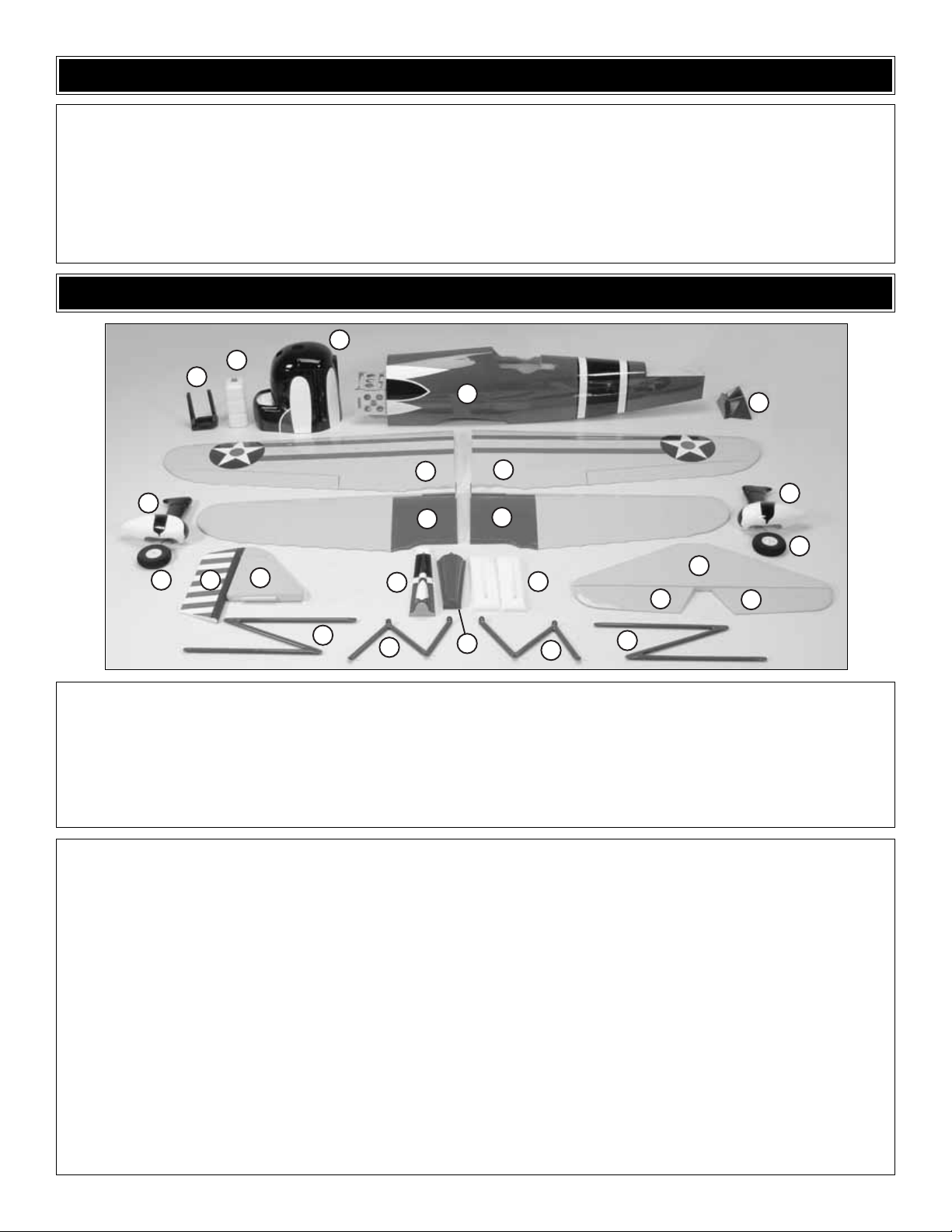
1 Left Top Wing
2 Right Top Wing
3 Left Bottom Wing
4 Right Bottom Wing
5 Fuselage
6 Stabilizer
7 Fin
8 Elevators (2)
9 Rudder
10 Fin Cover
11 Cowl
12 Molded Exhaust (2)
13 4" Foam Wheels (2)
14 Fuel T ank
15 “N” Struts (2)
16 Left Center Cabane
17 Right Center Cabane
18 Turtle Deck
19 Wind Screen
20 Engine Mount Halves (L&R)
21 Landing Gear Cover
Kit Contents (Photographed)
Forward Top Wing Joiner (3)
Forward Bottom Wing Joiner (3)
Aft Top Wing Joiner (1)
Aft Bottom Wing Joiner (1)
Tail Gear Wire w/Bushing (1)
Aluminum Landing Gear (1)
Guns (2)
Stopper Set (1)
Clunks (2)
Aluminum Tubes (3)
Colored Fuel Tubing (3)
Pickup Tube (2)
Radio Tray (1)
6.4x6.4x44mm Hardwood
Stick (4)
“N” Strut Brackets (8)
#64 Rubber Band (3)
Handle Plates (2)
Handle Ends (8)
Handle Spreaders (8)
Handle Centers (4)
Weight Box Bottom (1)
Weight Box Top (1)
Weight Box Front (1)
Weight Box Back (1)
Weight Box Sides (2)
Weight Box Sticks (2)
Cockpit Coaming (1)
Pilot (1)
1" Tail Wheel (1)
#8 x 5/8" Sheet Metal Screw
8-32 Blind Nuts (4)
8-32 x 1-1/4" SHC Screw (4)
#8 Washer (8)
#8 Lock Washer (8)
8-32 x 1" SHC Screw (4)
4-40 x 1/2" SHC Screw (20)
4-40 x 3/4" SHC Screw (4)
#4 Lock Washer (12)
#4 Nylon Lock Nut (8)
#4 Flat Washer (28)
3/16" Axles (2)
3/16" Wheel Collars (4)
6-32 Set Screws (2)
Nylon Axle Nut (2)
#2 x 3/8" Sheet Metal Screw (2)
#2 Flat Washer (2)
#4 x 1/2" SMS (32)
4-40 x 12" Pushrod (2)
Large Control Horn (5)
4-40 Threaded Metal Clevis (5)
.093" Solder Clevis (4)
4-40 Nut (5)
Clevis Retainers (10)
4-40 x 36" Threaded One End
Pushrod (3)
2-56 x 17-1/2" Threaded One
End Pushrod (1)
Nylon Clevis (1)
Brass Pushrod Connector (1)
Nylon Pushrod Keeper (1)
4-40 x 1/4" SHC screw (1)
24" Gray Outer Prod Tube (1)
6-32 x 1/4" SHC Screw (2)
Hinge Strip (1)
1/4-20 x 2" Nylon Wing Bolts (2)
1/4-20 Blind Nuts (2)
3/32" Wheel Collar (1)
4-40 Set Screw (1)
4-40 Blind Nut (4)
4-40 x 1" SHC Screw (4)
Kit Contents (Not Photographed)
KIT CONTENTS
Before starting to build, take an inventory of this kit to make sure it is complete, and inspect the parts to make sure they
are of acceptable quality. If any parts are missing or are not of acceptable quality , or if y ou need assistance with assemb ly,
contact Great Planes Product Support. When repor ting defective or missing parts, use the part names exactly as they
are written in the Kit Contents list on this page.
Great Planes Product Support:
Telephone: (217) 398-8970, ext. 5
Fax: (217) 398-7721
E-mail:
airsupport@greatplanes.com
KIT INSPECTION
11
14
20
5
19
21
913
7
15
18
16
10
2
21
4
13
6
12
17
8
15
8
1
3
Page 6

6
ORDERING REPLACEMENT PARTS
Replacement parts for the P-6E Hawk ARF are available using the order numbers in the Replacement Parts List that
follows.The fastest, most economical service can be provided by your hobby dealer or mail-order compan y. Parts may also
be ordered directly from Hobby Services, but full retail prices and shipping and handling charges will apply. Illinois and
Nevada residents will also be charged sales tax.
To locate a hobby dealer, visit the Great Planes web site at www.greatplanes.com. Choose “Where to Buy” at the bottom
of the menu on the left side of the page. Follow the instructions provided on the page to locate a U.S., Canadian or
International dealer. If a hobby shop is not available, replacement parts may also be ordered from Tower Hobbies at
www.towerhobbies.com, or by calling toll free (800) 637-6050, or from Hobby Services by calling (217) 398-0007, or via
facsimile at (217) 398-7721. If ordering via fax, include a Visa®or MasterCard®number and expiration date for payment.
Mail parts orders and payments by personal check to:
Hobby Services
3002 N Apollo Drive, Suite 1
Champaign IL 61822
Be certain to specify the order number exactly as listed in the
Replacement Parts List.
Pa yment b y credit card or personal
check only; no C.O.D.
If additional assistance is required for any reason, contact the appropriate Product Support by telephone at (217) 398-8970
or by e-mail at
productsupport@greatplanes.com
.
Replacement Parts List
Or
der Number Description How to Purchase
Missing pieces ................................................Contact Product Support
Instruction manual...........................................Contact Product Support
Full-size plans.................................................Not available
Kit parts listed below .......................................Hobby Supplier
GPMA2845............Bottom Wing
GPMA2846............T op Wing
GPMA2847............Fuselage
GPMA2848............Tail Set
GPMA2849............Cowl
GPMA2850............Landing Gear
GPMA2851............Wheel Pants
GPMA2852............Inter plane Struts
GPMA2853............Cabane Struts
GPMA2854............Wind Screen
GPMA2855............Decal Set
GPMA2856............Strut Brackets
GPMA2857............Pilot
Page 7
❏ 1.If you have not done so already, remove the major parts
of the kit from the box and inspect for damage. If any par ts
are damaged or missing, contact Product Support at the
address or telephone number listed in the “Kit Inspection”
section on page 5.
❏ 2. Remove the tape and separate the ailerons from the
wing and the elevators from the stab. Use a covering iron
with a covering sock on high heat to tighten the covering if
necessary .Apply pressure over sheeted areas to thoroughly
bond the covering to the wood.
Do the right top wing first, so your work matches the
photos the first time through.You can do one wing at a
time, or work on them together.
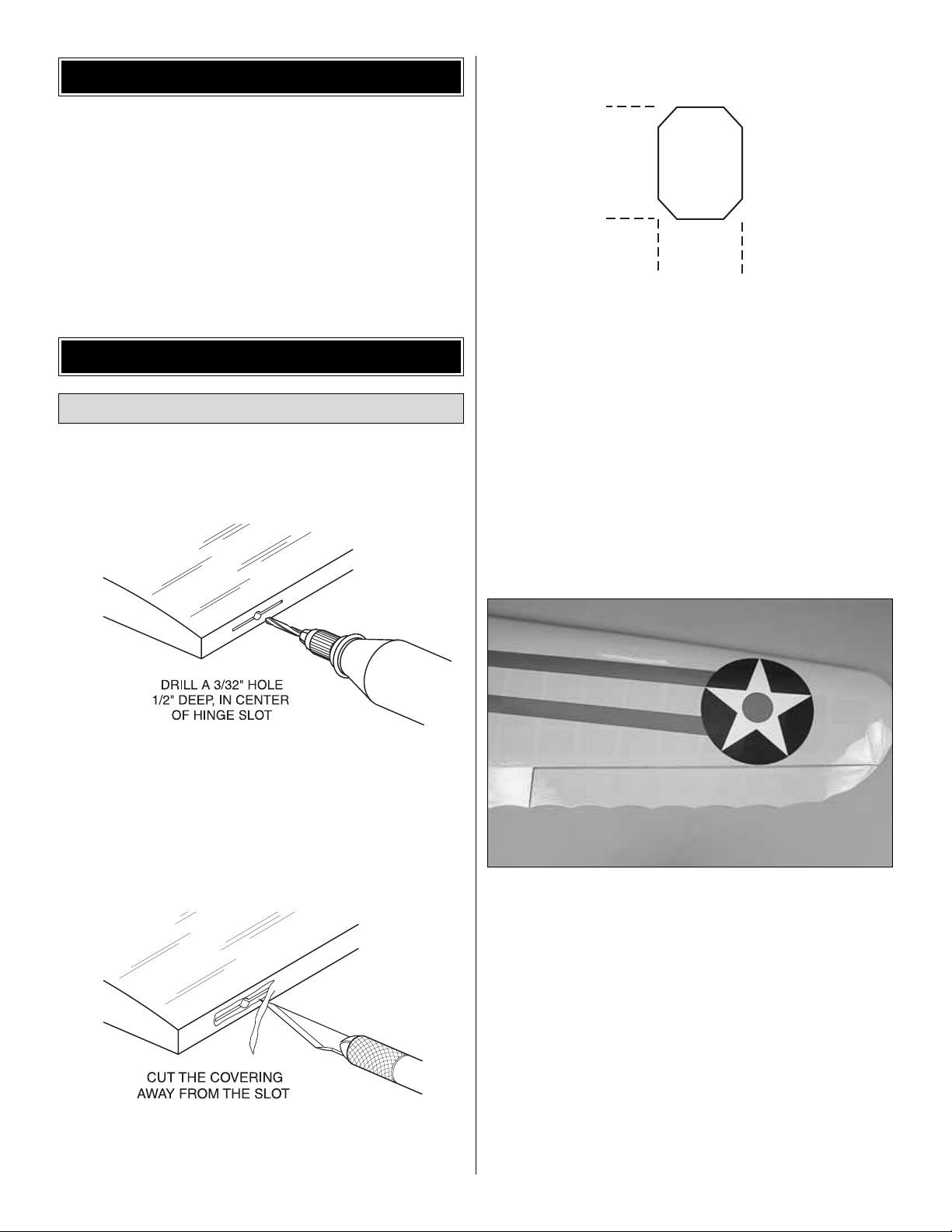
❏❏1. On the r ight top wing panel, drill a 3/32" [2.4mm]
hole, 1/2" [13mm] deep in the center of each hinge slot to
allow the CA to “wick”in.Follow-up with a #11 blade to clean
out the slots. Hint: If you have one, use a high-speed rotary
tool to drill the holes.
❏❏2. Use a sharp #11 blade to cut a strip of covering
from the hinge slots in the wing and aileron.
❏❏3. Cut four 3/4" x 1" [19 x 25mm] hinges from the CA
hinge strip. Snip off the cor ners so they go in easier.
❏❏4. Test fit the ailerons to the wing with the hinges. If
the hinges don’t remain centered, stick a pin through the
middle of the hinge to hold it in position.
❏❏5. Remove any pins you may have inserted into the
hinges.Adjust the aileron so there is a small gap between the
LE of the aileron and the wing.The gap should be small, just
enough to see light through or to slip a piece of paper through.
❏❏6. Apply six drops of thin CA to the top and bottom of
each hinge. Do not use CA accelerator. After the CA has
fully cured, test the hinges by pulling on the aileron.
❏ 7. Repeat steps 1- 6 for the left top wing panel.
Installing the Ailerons
BUILD THE WINGS
PREPARATIONS
7
1"
[25mm]
3/4"
[20mm]
Page 8
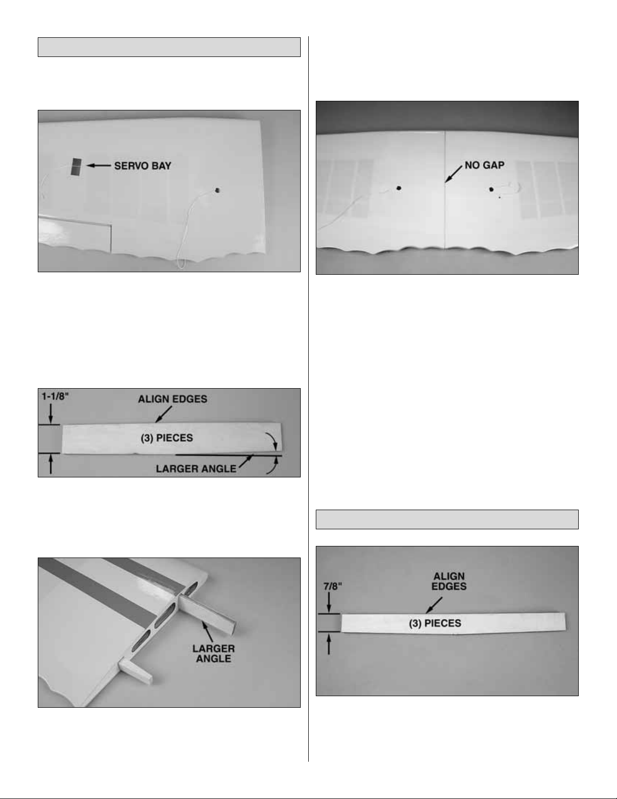
❏❏1. Cut away the covering from the servo bay in the
bottom of the right top wing panel.
❏❏2. A string is taped inside the servo bay. Carefully
remove the string from the servo bay and tape it to the outside
of the wing to prevent it from dropping bac k into the wing.The
other end of the string is under the hole towards the root of the
wing. Remove the covering from over the hole and thread the
string through the small hole and tape it to the wing.
❏ 3. Repeat steps 1 and 2 for the left top wing panel.
❏ 4. Locate two 1/8" [3mm] and one 1/16" [1.5mm] thick by
1-1/8" [28.6mm] wide plywood wing joiners. Using 6-minute
epoxy, glue the three joiners together to form one 5/16"
[7.5mm] thick wing joiner. Make sure that all three wing
joiners are aligned.
❏ 5. After the glue has cured, test fit the wing joiner into the
top wing panels. Note that the wing joiner has a larger angle
on one edge.The larger angle goes toward the bottom of the
wing.Also insert the larger hardwood trailing edge wing joiner.
❏ 6.To check that the joiners are properly installed, position
the top wing upside-down on your flat building surface.The
wing should lay flat. If it does not, remove the forward wing
joiner, flip it over and reinstall it in the wing panels.
❏ 7.When you are satisfied with the fit of the joiners, glue
the forward and aft wing joiners into the top wing panels with
30-minute epoxy. Be sure that the forward wing joiner is
installed properly.When gluing the wing panels together be
sure to get glue into the joiner pockets in the wing.This can
be done by applying the glue into the pockets with a small
stick.Apply glue to the pockets, the joiners and the root ribs
of the wing panels.
Before the glue cures, set the wing upside-down on your flat
building surface. Put small weights on the wing to keep it
lying flat while the glue cures.
❏ 8. Hold the wing together with masking tape while the
glue is curing.Before the epoxy cures, the e xcess epo xy can
be removed with denatured alcohol and a paper towel.
❏ 1. Locate three 1/8" [3mm] and one 1/16" [1.5mm] thick
by 7/8" [22mm] wide plywood wing joiners. Using 6-minute
epoxy, glue the three joiners together to form one 5/16"
[7.5mm] thick wing joiner. Make sure that all three wing
joiners are aligned.
Join the Bottom Wing Panels
Join the Top Wing Panels
8
Page 9
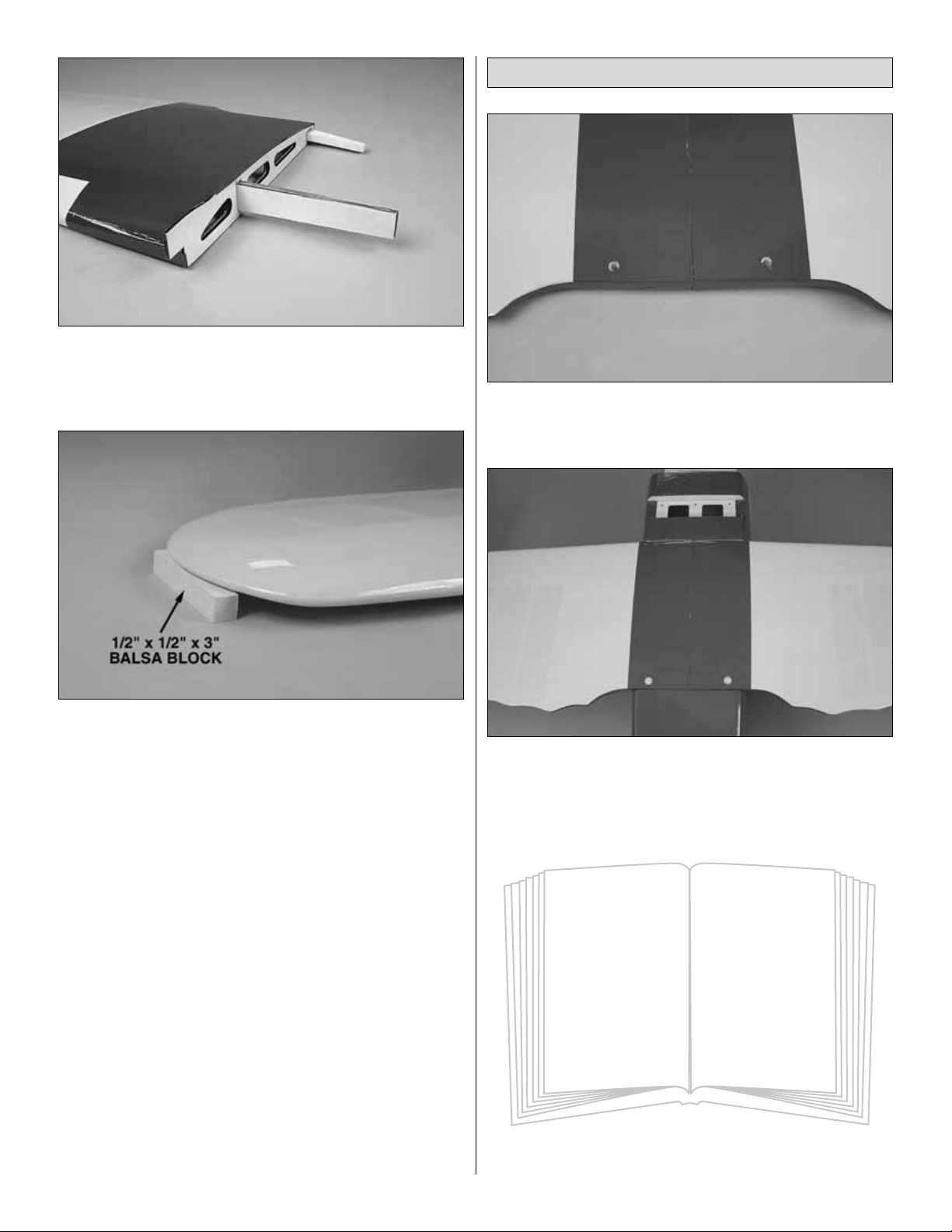
❏ 2. After the glue has cured, test fit the wing joiner into the
bottom wing panels. Note that the wing joiner is angled to
provide dihedral in the bottom wing. Also insert the smaller
hardwood trailing edge wing joiner.
❏ 3.To check that the joiners are properly installed, position
the wing upright on your building surface .Place the included
1/2" x 1/2" x 3" [12.7mm x 12.7mm x76.2mm] balsa block
under each wing tip. The center of the wing should be
resting on your building table.
❏ 4.When you are satisfied with the fit of the joiners, glue
the forward and aft wing joiners into the bottom wing panels
with 30-minute epoxy. Be sure that the forward wing joiner is
installed properly.When gluing the wing panels together be
sure to get glue into the joiner pockets in the wing.This can
be done by applying the glue into the pockets with a small
stick.Apply glue to the pockets, the joiners and the root ribs
of the wing panels.
Before the glue cures, set the wing upright on your building
surface.Position the two blocks under the wing tips.Put small
weights on the wing to keep it lying flat while the glue cures.
❏ 5. Hold the wing together with masking tape while the
glue is curing.Before the epoxy cures, the e xcess epo xy can
be removed with denatured alcohol and a paper towel.
❏ 1. Cut the covering from over the two wing bolt mounting
holes at the aft edge of the bottom wing.
❏ 2. Attach the bottom wing to the fuselage with two
1/4-20 x 2" [50.8mm] nylon bolts.
Install the Bottom Wing
9
Did you know? ....
The original P-6 had a designation
as XP-6 and was designed for the
1927 National Air Race, placing
2nd with an average speed of
189 mph. The plane that beat
it was the Curtiss XP-6A.
Page 10
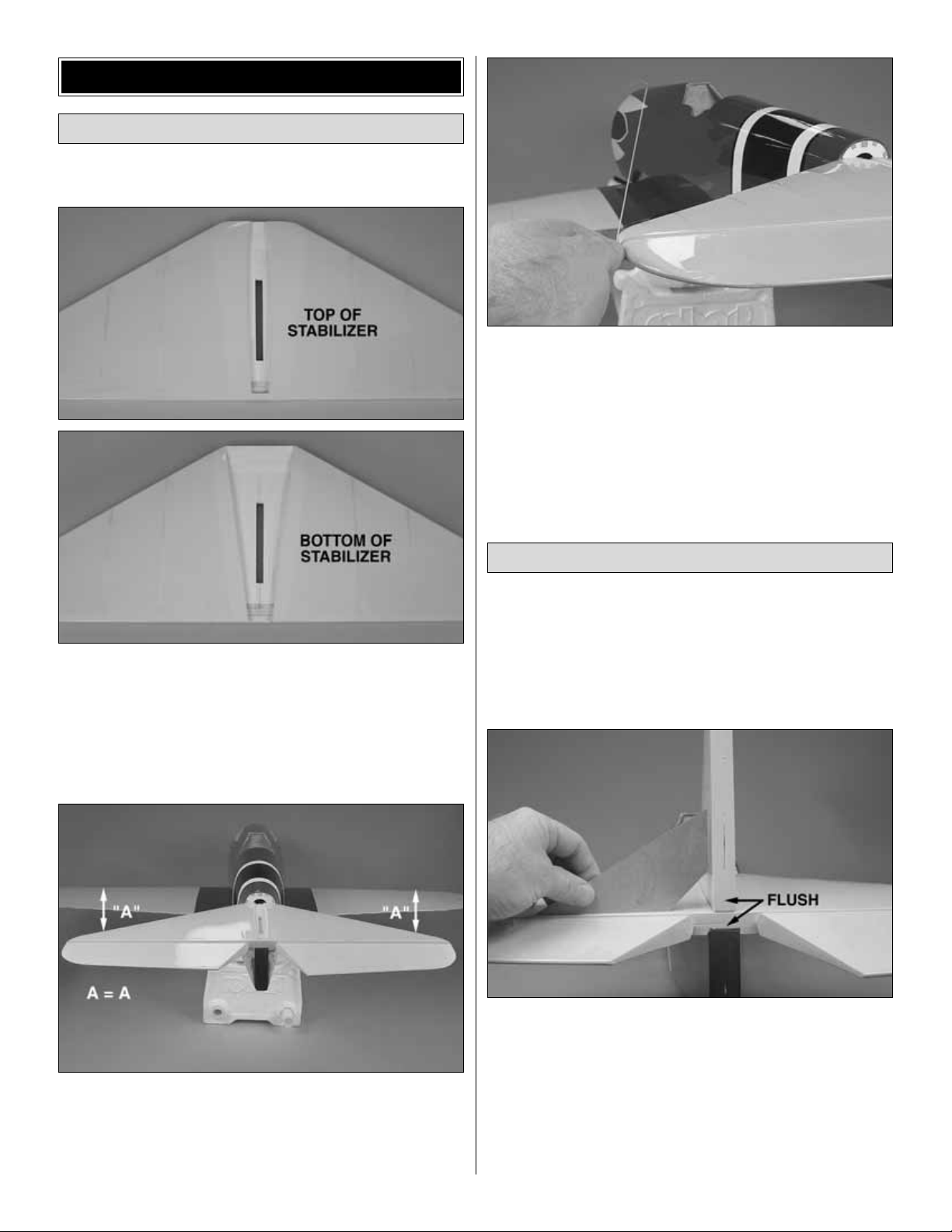
❏ 1. Remove the two elevators from the stabilizer.
❏ 2.Trim the covering from the top and bottom of the center
of the stabilizer.
❏ 3. Cut six 3/4" x 1" [19mm x 25.4mm] hinges from the
hinge strip. Install both elevators and hinges on the
stabilizer, using the same method that was used to install
the ailerons on the wing.
❏ 4. Test fit the stabilizer on the fuselage. Note that the
cutout in the stabilizer fits over the fuselage .Stand back and
look at the stabilizer in relation to the wing. The stabilizer
should be parallel with the wing. If not, sand the stabilizer
saddle until the stabilizer and wing are aligned.
❏ 5. Measure the distance from the tip of the stabilizer to
the center of the fuselage at the firewall. Adjust the position
of the stabilizer until they are equal.
❏ 6. When satisfied with the fit, use 30-minute epoxy to
glue the stabilizer to the fuselage. Double-check the
stabilizer alignment while the epoxy is curing.
❏ 1. Fit the fin in the cutout in the top of the stabilizer.Make
sure the bottom of the fin seats against the top of the
stabilizer in the cutout. If needed, trim the corners of the
alignment block on the bottom of the fin. Make sure the
trailing edge of the fin is flush and aligned with the aft end of
the fuselage.
❏ 2. Use a 90-degree triangle to check that the fin is
perpendicular to the stabilizer.This should be checked at the
trailing edge of the stabilizer and fin.
❏ 3. Use 6-minute epoxy to glue the fin to the stabilizer. Use
masking tape to hold the fin in position, double-checking the
alignment while the epoxy is curing.Do not glue the front of the
fin to the turtledeck. Leave a 1/32" [.8mm] gap between the fin
and the turtledeck.The fin cover must fit between the two.
Install the Fin and Rudder
Install the Stabilizer and Elevator
INSTALL THE STABILIZER AND FIN
10
Page 11
❏ 4. Use a canopy scissors or hobby knife to trim the plastic
fin cover along the molded cut lines.Trial fit the cover over
the fin.We found that cutting the front center from the cover
allowed the fin to fit better. Tr im the aft end of the cover so
that it is flush with the trailing edge of the fin.
❏ 5. Use sandpaper to roughen the inside of the cover
where it contacts the fin and stabilizer. Mark the outline of
the cover on the fin and stabilizer using a felt tip pen.
Remove the cover and use a pin to poke small holes where
the cover will be attached.This will help the glue adhere to
the stabilizer and fin.
❏ 6. Glue the cover to the stabilizer, fin and fuselage using
CA, epoxy or canopy glue .We prefer to use epoxy or canop y
glue to allow time to position the cover and clean off the
excess glue.Use masking tape to hold the cover in position
until the glue cures.
❏ 7. Cut three 3/4" x 1" [19mm x 25.4mm] hinges from the
hinge strip.Test fit the r udder to the fin and fuselage.
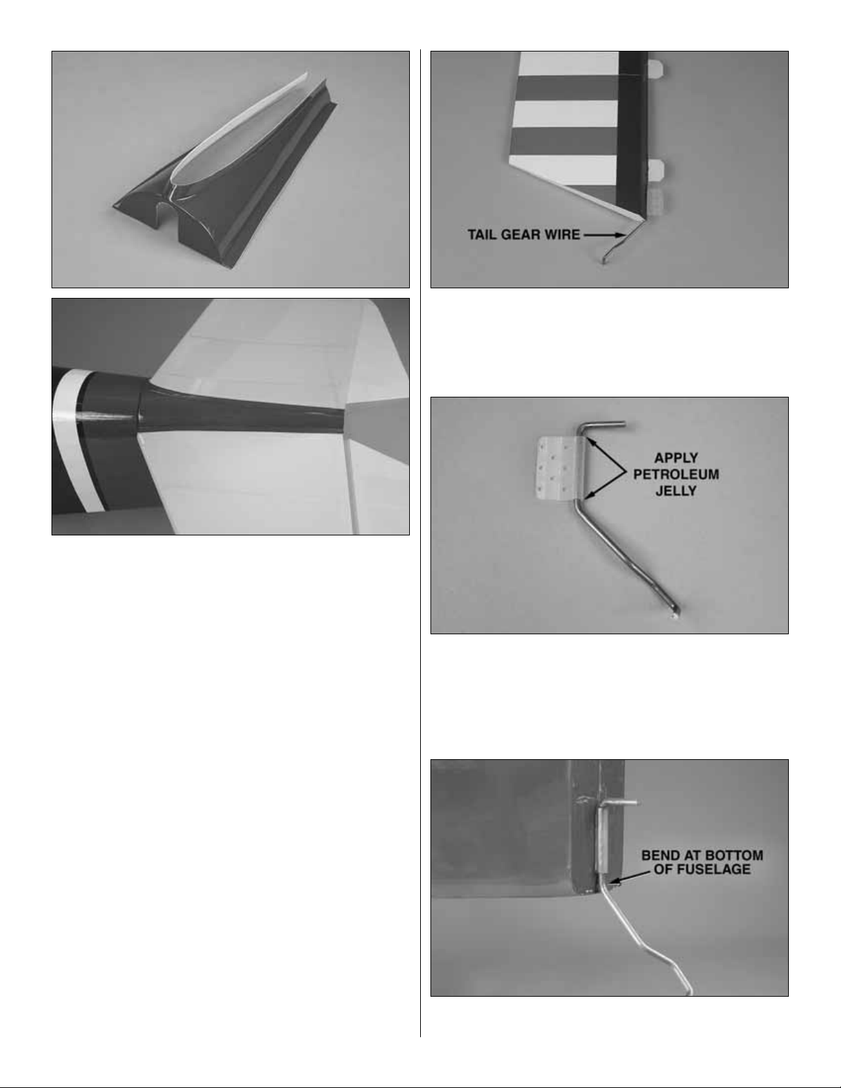
❏ 8.Trim the covering from over the slot at the lo wer leading
edge of the rudder.Test fit the tail gear wire in the slot.
❏ 9. Apply petroleum jelly to the tail gear wire above and
below the tail gear bushing.Do not get petroleum jelly on the
bushing or the wire that will be glued in the rudder.
❏ 10. Use epoxy to glue the tail gear bushing in the aft end
of the fuselage.
11
Page 12

❏ 11. Put epoxy in the tail gear wire hole in the leading
edge of the rudder. Do not get epoxy in the slot. Before the
epoxy cures, use thin CA to glue the CA hinges in the fin and
rudder using the same method as before.
❏ 12. Install the 1" tail wheel on the tail gear wire. Secure
the wheel to the wire with a 3/32" [2.4mm] wheel collar and
4-40 set screw. Make sure to use thread lock on the set
screw to prevent it from coming loose.
❏ 1. Attach the aluminum main landing gear to the fuselage
with six #8 x 5/8" [15.9mm] sheet metal screws.The straight
side edge of the main gear faces the front.
❏ 2. Glue the belly pan back in place with a few dabs of
silicone glue. Using silicone will allow you to remove the
belly pan easily should you ever have to get access to the
landing gear bolts.
❏ 3. Use a hacksaw or cutoff wheel on a rotary tool to cut
the two 3/16" (4.8mm) axles to a length of 1-3/8" [35mm]
long. Also grind a flat spot at the end of the axle.
❏❏4.Slide a landing gear cover ov er one side of the landing
gear. Attach the axle to the landing gear with a 5/16" [8mm]
nylon nut. Make sure the flat spot is facing out of the landing
gear cover.
INSTALL THE MAIN LANDING GEAR
12
Did you know? ....
The P-6E Hawk was of mixed
construction. The wings had
wooden spars and ribs, and the
fuselage was a welded steel-tube
structure, all covered with fabric.
Metal framed ailerons were fitted to
the upper wing only. Armament was
two 30 caliber Colt-Browning
machine guns.
Page 13

❏❏5.Install a 4" [102mm] foam wheel on the axle follow ed
by a 3/16" [4.8mm] wheel collar. Secure the wheel collar to
the axle with a 6-32 set screw. Make sure to use thread lock
on the set screw and tighten the set screw against the flat
spot on the axle.
❏❏6. Attach the landing gear cover to the landing gear
with two 4-40 x 1/2" [12.7mm] socket head cap screws and
two #4 flat washers.
❏ 7. Go back to step 4 and install the other landing gear
cover and wheel.
❏ 1. Use the template on page 35 to locate the four mounting
holes for the engine mount. Align the marks on the template
with the embossed lines on the firewall. Use a 7/32" [5.5mm]
drill bit to drill four mounting holes through the firewall.
❏ 2. Press the four 8-32 blind nuts into the back of the
firewall. Use an 8-32 x 1" [25.4mm] socket head cap screw
and #8 flat washer to fully seat the blind nuts in the firewall.
Apply a few drops of thin CA around each b lind nut to secure
it in the firewall.Make sure not to get CA in the threads.
❏ 3. Cut the tabs from the engine mount. Install the engine
mount (inverted) to the firewall with four 8-32 x 1-1/4" [32mm]
socket head cap screws , #8 flat washers and #8 loc k w ashers.
❏ 4. Slide the cowl over the front of the fuselage. Align the
painted feathers on the cowl with the f eathers on the fuselage.
Use masking tape to hold the cowl in position. Measure from
the front of the cowl to the firewall. The distance should be
approximately 5-7/8" [149mm]. Due to slight manufacturing
differences, this distance may be slightly different.
Mount the Engine
INST ALL THE ENGINE
13
Page 14

❏ 5. Remove the cowl and position the engine on the mount
so the distance from the firewall to the front of the thrust
washer measures 5-15/16" [151mm]. If the distance
measured in the previous step was different than 5-7/8"
[149mm], add 1/16" to 3/32" [1.6mm to 2.4mm] to the
measurement. This is the distance the front of the thrust
washer should be from the firewall. Mar k the location of the
engine on the mount. The Great Planes Dead Center™Hole
Locator (GPMR8130) works well for this. Drill through the
marks you have made on the engine mount with a #29 or
9/64" [3.6mm] drill bit.Tap each of the holes with an 8-32 tap.
❏ 6. Install the engine onto the mount with four each,
8-32 x 1" [25mm] socket head cap screws, #8 flat washers
and #8 lock washers.
❏ 1. Slide the cowl over the engine as far as possib le .Mark
the location at which the head of the engine hits the cowl.
Remove the cowl and cut a small hole in the cowl at the
mark. First cut the hole undersize, checking the fit as you
enlarge the hole.
❏ 2. Use four pieces of thin cardboard or plastic to mark the
location for the cowl mounting screws on the fuselage. The
location should be 1/8" [3.2mm] from the front of the forward
former, centered on the four plywood sticks.
❏ 3. Once the hole in the cowl is large enough to clear the
engine head, slide the cowl over the fuselage. Install a
propeller on the engine.
❏ 4. Align the cowl with the feathers on the side of the
fuselage. Also center the thrust washer in the front of the
cowl. Make sure the propeller clears the cowl by at least
1/16" [1.6mm].Use masking tape to hold the cowl in position.
❏ 5. Drill a 3/32" [2.4mm] pilot hole through the cowl and
fuselage at each of the four cowl mounting locations.
Enlarge the holes to 1/8" [3.2mm] in the cowl only.
❏ 6. Attach the cowl to the fuselage using four #4 x 1/2"
[12.7mm] sheet metal screws and four #4 flat washers.
Mount the Cowl
14
Page 15

❏ 7. Now that the cowl is properly mounted to the fuselage
you can finish the hole for the engine head. You can also
make a template from thin cardboard to locate the hole for
the exhaust and needle valve.
❏ 8. Also, while you hav e the co wl remo ved, apply a couple
of drops of thin CA to each of the four cowl mounting holes
in the fuselage to harden the wood.
❏ 1. Remove the components from inside the fuel tank.
Install the three aluminum tubes in the fuel tank stopper.You
will need to use a hobby knife to open the third hole in the
rubber stopper.Slide the small metal plate over the tubes and
thread the screw into the plate until it makes contact with the
back of the rubber stopper.Do not tighten the screw.
❏ 2. Carefully bend one of the long tubes so that it will
angle up toward the top of the fuel tank when inserted. Do
not kink the tube.Mark a “P” on the outside of the front plate
to designate pressure.
❏ 3. Install a piece of fuel tubing on each of the other two
tubes.Attach a clunk on the ends of the tubes.Mark a “C”on
the outside of the front plate by the short tube, designating
carb.Mark an “F” by the remaining tube, designating fill.
❏ 4. Insert the tank stopper in the fuel tank so that the bent
tube is towards the top of the fuel tank. Check that the two
clunks are able to move freely when the stopper is inserted
completely.Then, tighten the screw in the stopper to seal the
fuel tank. Write “top” on the side of the fuel tank where the
pressure tube sticks up.
❏ 5.Install the three pieces of fuel line on the three aluminum
fuel tubes sticking out the front of the fuel tank. Write on the
firewall box which color of tubing goes to the carb uretor , fill and
pressure. Inser t the fuel tank into the fuel tank compartment,
routing the fuel line out to the engine.Make sure the top of the
tank faces the top of the fuselage.Insert the stopper portion of
the tank in the hole in the forward former.
Install the Fuel Tank
15
Page 16

❏ 6. Connect the correct fuel line to the carberator and the
fuel line plug to the fill line. The pressure line will be
connected to the muffler once the cowl has been installed.
❏ 7. Use a #64 rubber band to secure the aft end of the fuel
tank to the former.
❏ 1. Our test samples required some weight in the nose to
balance at the forward CG. We recommend wrapping the
receiver battery in foam and positioning it on top of the fuel
tank. Use scrap sticks to hold the battery in place.
❏ 2. Glue two of the 1/4" x 1/4" x 1-3/4" [6.4mm x 6.4mm x
44mm] hardwood sticks to the former at the front of the wing
saddle. The sticks should be flush with the two radio tray
mounting slots.
❏ 3. Position the other two 1/4" x 1/4" x 1-3/4" [6.4mm x
6.4mm x 44mm] hardwood sticks flush with the aft edge of
the radio tray and protruding 3/8" [9.5mm] out each side.
Drill a 1/16" [1.6mm] pilot hole through the radio tray and
hardwood stick. Mount the sticks to the radio tray with #2 x
3/8" [9.5mm] sheet metal screws and #2 washers.
❏ 4. Insert the radio tray in the former at the front of the
wing saddle. Carefully apply a drop of medium CA to the
hardwood sticks at the aft edge of the radio tray. Do not get
CA on the radio tray. Position the radio tray flush with the top
of the arms on the aft radio tray former. After the CA has
cured, remove the two screws in the radio tray and remove
the tray. Use thin CA to permanently glue the two hardwood
sticks to the former.
❏ 5. Reinstall the radio tray and drill two 1/16" [1.6mm] pilot
holes at the front of the radio tray, through the tray and
hardwood sticks. Attach the tray to the sticks with two
#2 x 3/8" [9.5mm] sheet metal screws and #2 washers.
❏ 6. Install the throttle servo into the servo opening. Drill
through the servo mounting holes with a 1/16" [1.6mm] drill
bit.Remove the servo from the servo opening.Install and then
remove a servo mounting screw into each of the holes you
have drilled. Apply a drop of thin CA into the holes to harden
the threads.Once the glue has cured, install the servo into the
servo opening using the hardware included with your servo.
Center the throttle stick on the transmitter and then center the
throttle servo trim. Install a servo arm as shown.
Install the Throttle Servo
16
Page 17

❏ 7.Install a brass screw-lock pushrod connector on the throttle
servo arm. Secure it with a nylon keeper.Thread a 4-40 x 1/4"
[6.4mm] socket head cap screw in the pushrod connector.
❏ 8. Drill a 3/16" [4.8mm] hole through the forward former,
inline with the throttle arm. Insert the 3/16" x 24" [4.8mm x
610mm] gray outer pushrod in the hole and route it through
the fuel tank bay. If needed, drill a 3/16" [4.8mm] hole in the
former at the front of the wing saddle to allow the outer
pushrod to align with the throttle servo. Use sandpaper to
roughen the pushrod tube before gluing it to the formers.
❏ 9. Thread a nylon clevis 14 turns onto the 2-56 x 17"
[432mm] metal pushrod. Slide a silicone clevis retainer over
the clevis.Inser t the pushrod in the outer pushrod tube and
through the pushrod connector on the throttle servo. Attach
the clevis to the throttle arm on the carburetor.
❏ 10. Switch on your transmitter and connect the throttle
servo and receiver battery to the receiver. Adjust the throttle
pushrod so that the throttle opens and closes correctly .Tighten
the 4-40 socket head cap screw, in the pushrod connector,
against the throttle pushrod and cut off the excess pushrod.
❏ 1. Use sandpaper to roughen the backside of the two holes
for the machine guns and the mounting rings on the machine
guns. Clean the area with denatured alcohol.
Finish Assembling the Cowl
17
Page 18

❏ 2. Use epoxy to glue the machine guns in the cowl.
❏ 3. T rim the exhaust stacks as shown.We used black paint
to fill in between the stacks.An alternative is to fill the back of
the stacks with a mixture of epoxy and micro balloons.Once
the epoxy cures, trim the exhaust stacks around the bottom.
❏ 4. Use epoxy to glue the exhaust stacks to the co wl.Note
that the stacks face outward, not upward.
❏ 5. This completes the installation of the engine and cowl.
You can now reinstall the cowl. Make sure when installing the
cowl that the fuel fill line is easy to access and the muffler
pressure line comes out the muffler clearance hole.
❏ 1. Cut the covering from the pushrod tube openings at the
rear of the fuselage. There are two located on the left side
and one located on the right. If you have trouble finding the
openings, slide a .096" x 36" [914mm] pushrod wire into the
tubes from inside of the fuselage, sliding it into the tube until
it pushes the covering away from the fuselage slightly.This is
where you should cut the covering away from the tubes.
❏ 2. Locate three .096" x 36" [914mm] pushrod wires
threaded on one end. Thread a 4-40 nut onto the threaded
end of each wire. Thread a 4-40 metal clevis 15 turns onto
each wire. Install a silicone clevis retainer onto the clevis.
Install the Rudder and Elevator Servos
INSTALL THE RADIO SYSTEM
18
Did you know? ....
On July 10, 1931, the first order
for 46 of the P-6E Hawks was
placed. Of the 656 Hawks built,
more than 1/3rd were exported to
foreign countries. The lifespan in
the U.S. Army Air Corp was short
due to the development of the
Boeing P-26A monoplane.
Page 19

❏ 3. On the left side of the fuselage, slide one wire into the
opening closest to the back of the fuselage. Install a large
nylon control horn onto the clevis.Position the control horn on
the rudder so that the clevis pin is in line with the hinge line.
Mark the location for the screw holes.Drill through the marks
you made with a 3/32" [2.4mm] drill bit, drilling only into the
plywood plate.Do not drill through the rudder! Install and then
remove four #4 x 1/2" [12.7mm] sheet metal screws. Apply a
couple drops of thin CA into the holes. Once the glue has
cured, mount the horn to the rudder with the screws.
❏ 4. Install the two elevator pushrods using the same
procedure used for the rudder. Be sure when installing the
control horn on the left elevator that you install it so it does
not conflict with the rudder control horn.
❏ 5. Place your rudder ser vo into the servo tray as shown.
Drill a 1/16" [1.6mm] hole through each of the mounting
holes. Remove the servo, then install and remove a servo
mounting screw into each hole.Apply a couple drops of thin
CA into the holes to harden the threads.When the glue has
cured, permanently mount the servo to the servo tray.
❏ 6. Center the rudder and the rudder ser vo. Then, install
the servo arm. Install a metal solder clevis in the last hole in
the servo arm. Mark the pushrod wire at the end of the clevis.
❏ 7. Remove the rudder pushrod and solder clevis from the
plane.Position the cle vis ne xt to the rudder pushrod so that the
clevis aligns with the mark.Cut the rudder pushrod as shown.
❏ 8. Use silver solder to solder the solder clevis onto the
end of the rudder pushrod.
HOW TO ACHIEVE A GOOD SOLDER JOINT
A. Roughen the area to be soldered with fine sandpaper.
Thoroughly clean the area with denatured alcohol.
B. Assemble the items to be soldered.
19
Page 20

C. Apply a small drop of solder flux to the joint.
D. Heat the area to be soldered. Apply solder to the heated
area.The metal must get hot enough to melt the solder and
the solder must flow into the joint. Do not melt the solder by
touching it to the soldering iron.
E. Do not move the parts until the solder has cooled.
F. Clean off the excess flux with alcohol.
G.Test the joint by pulling on it.
H. Apply a light coat of oil to the joint to prevent rust.
❏ 9. Once the solder clevis has cooled, install a silicone
clevis keeper on the clevis. Remove the 4-40 metal clevis
and 4-40 nut and insert the rudder pushrod in the rudder
outer pushrod tube. Connect the clevis to the rudder servo
arm. Reinstall the 4-40 nut and clevis and connect it to the
rudder control horn.
❏ 10. Install the elevator servo and attach a solder clevis to
one of the elevator pushrods using the same method as
used for the rudder.
❏ 11.Insert the elevator pushrod in the elevator outer pushrod
tube.Center the other elevator. Bend the pushrod to the same
angle as the first elevator pushrod where the two meet.
❏ 12. Cut the second elevator pushrod 1/4" [6.4mm] behind
the solder clevis.
❏ 13. Remove the first elevator pushrod and install two
3/16" wheel collars on the pushrod. Reinstall the first
elevator pushrod in the outer pushrod tube. Slide the two
wheel collars over the second pushrod. Secure the wheel
collars to the two elevator pushrods with two 6-32 x 1/4"
[6.4mm] socket head cap screws. Make sure to use
threadlock on the two screws. Make sure the cap head
screws do not hit the fuselage former.
❏ 14. Reinstall the clevis on the first elevator pushrod and
reattach it to the elevator control horn.
❏ 15. Wrap the receiver in 1/4" [6.4mm] foam. Use #64
rubber bands to hold the receiver to the radio tra y. Route the
receiver antenna out the antenna tube installed in the top of
the fuselage. Plug the ser vos into the receiver.
❏ 16. We installed the radio switch and the battery charge
jack in the front of the cockpit. Place the pilot in the cockpit
as your guide for positioning the switch and charge jack.
❏ 17. Connect the batter y to the radio switch and secure
the ends of the leads with heat-shrink tubing, tape or some
other method for securing the leads.
20
Page 21

❏❏1. On the right top wing, install a 6" [152.4mm] servo
extension onto the servo lead. Secure the extension to the
lead with tape, a piece of heat-shrink tube or some other
method to keep them from coming unplugged.
❏❏2.Tie the string to the ser vo extension. At the root of
the wing the other end of the string is taped. Pull the string
and the servo lead through the small hole you cut the
covering from.Untie the string and tape the lead to the wing
to prevent it from falling back into the wing.
❏❏3. Install the servo into the servo opening. Drill
through the servo mounting holes with a 1/16" [1.6mm] drill
bit. Remove the servo from the servo opening. Install and
then remove a servo mounting screw into each of the holes
you have drilled. Apply a drop of thin CA into the holes to
harden the threads. Once the glue has cured, install the
servo into the servo opening using the hardware included
with your servo.Center the servo, then install a servo arm as
shown.The arm should be pointing towards the wing root.
❏❏4. Install a 4-40 nut, metal clevis and silicon clevis
keeper on a .096 x 12" [305mm] pushrod. Attach the clevis
to a large control horn in the second hole from the bottom.
Position the control horn on the aileron so that the pushrod
is inline with the outer hole in the aileron servo arm. When
positioned properly the control horn will rest on a plywood
plate in the aileron. Mark the location of the mounting holes
onto the aileron. Drill a 1/16" [1.6mm] hole on the marks,
drilling through the plywood plate but not through the top of
the aileron. Insert and remove a #4 x 1/2" [12.7mm] sheet
metal screw into each of the holes. Apply a couple drops of
thin CA into the holes to harden the threads. Once the glue
has cured attach the horn to the aileron with four #4 x 1/2"
[12.7mm] sheet metal screws.
❏❏5. Attach a metal solder clevis to the outside hole of
the aileron servo arm. Center the servo and the aileron.With
a fine-tip marker, mark the pushrod at the end of the clevis.
Use the same method to solder the aileron clevis to the
pushrod that was used to assemble the rudder pushrod.
❏❏6. Tr im the covering from the two aileron servo lead
exit holes in the side of the fuselage.
❏❏7. Connect the Y-harness for the ailerons to the
receiver. Route the two connectors out of the holes.
❏ 6. Repeat steps 1-5 for the left wing panel.
Install the Aileron Servos and Pushrods
21
Page 22

❏ 1. Attach the lower wing to the fuselage with the 1/4-20
nylon wing bolts.
❏❏2. Locate eight metal cabane mounting brackets.Set
four brack ets f or the top wing to the side.We will be installing
the brackets on the bottom wing first.
Do the left wing first so your work matches the photos
the first time through.
❏❏3. Look closely on the top of the bottom wing and you
will find small holes under the covering locating the blind
nuts for the “N” strut mounting bolts. Cut the covering from
each of the holes.Note: 4-40 Blind nuts have been installed
in the wing for all of the “N” struts and cabane mounting
bolts. All of the blind nuts are glued into the wing and have
a small wood plate backing them up. It is possible that a
blind nut could have a bit of glue in the threads. In most
cases the installation of the bolt should free the glue. If not,
run a 4-40 tap through the threads to clear the glue.
❏❏4. Mount the bottom wing cabane brackets in each of
the holes in the right wing panel with a 4-40 x 1/2" [13mm]
socket head cap screw and a #4 lock washer. Do not fully
tighten the bracket to the wing yet.
❏❏5. Note that the “N” strut has one leg that is slightly
longer than the other. The shorter leg goes toward the
leading edge of the wing. Attach the “N” strut to the brackets
as shown with 4-40 x 1/2" [13mm] socket head cap screws,
#4 washers and a 4-40 nylon lock nuts.
❏ 6. Go back and repeat steps 3-5 for the right wing panel.
❏ 7. Locate the holes and cut the covering from the blind nuts
in the bottom of the top wing.Four are located in the center of
the wing and two are located at each end of the wing.
❏ 8. Install the center cabanes with 4-40 x 3/4" [19mm]
socket head cap screws, #4 flat washers and #4 lock
washers. Be sure you mount the cabanes as shown.
❏ 9. Install the four remaining brackets in the blind nuts at
the wing tips of the top wing using 4-40 x 1/2" [13mm] socket
head cap screws and #4 lock washers.
INST ALL THE T OP WING
22
Page 23

❏ 10. Place the top wing onto the “N” struts. Attach the top
wing to the “N” struts with 4-40 x 1/2" [13mm] socket head
cap screws, #4 washers and 4-40 nylon lock nuts the same
way you installed the strut to the lower brackets.
❏ 11. Set the plane on its nose. Look at the relation of the
top wing to the bottom wing. Be sure the top wing is parallel
with bottom wing. Adjust the top wing as needed. Then
carefully set the fuselage back on the landing gear.
❏ 12.Without disturbing the top wing, verify that the cabane
mounting holes are positioned over the hardwood rails. If
they are not, check to see if you have mounted the center
cabanes and “N” struts properly. Also look at the top and
bottom wings from the side. They should look almost
parallel. If it appears that the leading edge of the top wing is
much higher, the “N” struts are possibly backwards.
❏ 13. Drill a 5/64" [2mm] hole through each of the four
mounting holes in the center cabanes.When you drill these
holes you must be drilling into the hardwood blocks located
in the fuselage, just under the covering.
❏ 14. Install and then remove a #4 x 1/2" [13mm] sheet
metal screw and #4 flat washer into each of the four holes.
Apply a couple drops of thin CA into each of the holes to
harden the threads. After the glue has cured, permanently
install the screws into the fuselage.
❏ 15. Once you have the center cabanes installed, tighten
the socket head cap screws holding the “N” strut brackets.
This kit comes with a convenient carrying handle for the
fuselage and the struts.
❏ 1. Locate all of the plywood parts of the carr ying handle.
❏ 2. Glue the four parts of each set together as shown to
make a pair 3/8" [10mm] thick.
❏ 3. Do the same with the remaining par ts as shown.
Build the Carrying Handle
FINISH THE FUSELAGE
23
Page 24

❏ 4. Glue the two parts shown onto one of the plywood
carrying handle par ts. Make sure the four holes are aligned.
❏ 5. Place the “N” struts onto the handle, leaving space
between the struts in the center of the handle as shown.The
remaining parts you glued together should be positioned
between the “N” struts. Once you are sure the struts and
the remaining pieces fit properly, glue the plywood parts to
the handle.
❏ 6. On the remaining handle part, install a 4-40 blind nut
into each of the corner holes.
❏ 7. Place the two “N”struts into the handle. Put the handle
top onto the part of the handle holding the struts and place
the completed handle on top of the cabanes. Secure the
handle to the cabanes with four 4-40 x 1" [25.4mm] socket
head cap screws and #4 flat washers. This is how the
completed handle looks when you are storing the parts or
taking the plane to the field.
24
Page 25

Our prototype model required the addition of nose
weight with engines at the bottom end of the
recommended range.We have included a box for you to
easily add the weight that most likely will be needed.
❏ 1. Locate the plywood parts that make up the nose weight
box.Glue the box together as shown.The box will be exposed
to engine vibration so be sure you have good glue joints.
❏ 2.Glue the two 1/8" x 1/4" x 3-1/4" [3 x 6.4 x 83mm] plywood
sticks together.Then glue them to the front of the box.
❏ 3. Fit the box cover to the box. Dr ill a 1/16" [1.6mm] hole
at the locations shown. Install and then remove a #2 x 3/8"
[9.5mm] sheet metal screw into each hole. Remove the
cover, and then apply a couple of drops of thin CA into the
holes in the box to harden the threads.
❏ 1. Locate the black cockpit coaming.Look closely and you
will see that there is a slit in it.Slide the coaming onto the side
of the cockpit as shown.Cut the coaming at a 45° angle at the
top.Cut a second piece for the other side.Now cut a piece to
go along the top.Glue the pieces in place with R/C 56 canopy
glue.This glue sticks well to MonoKote, eliminating the need
to cut any covering in order to expose wood for a good bond.
❏ 2. Cut the windscreen on the cut lines. Glue it in place
with R/C 56 canopy glue.
Finishing T ouches
Assemble the Nose Weight Box
25
Page 26

❏ 3. Cut the turtle deck on the cut lines and glue it in place
with R/C 56 canopy glue.
❏ 4. Your kit includes a pilot. Glue the pilot in the cockpit
using 6-minute epoxy.
The photos on the box show optional flying wires installed on
the plane.The materials we used for this are not included in
the kit but are readily availab le at an y f abric store f or less than
$10.00. The wires are made from an elastic cord typically
used for sewing an elastic cuff in a sleeve. The material is
commonly called, “Beading Cord Elastic.”
You will need approximately seven y ards, two small pac kages.
The method described here will provide a reasonably scale
appearance without the hassles typically associated with
flying wires. Because they are made from elastic there is no
need to tension them each time you put the plane together.
These wires will add approximately two minutes to the overall
assembly time of the plane at the flying field.
❏ 1. Measure from the fillet at the trailing edge of the stab
out toward the tip of the stab 7" [178mm] and make a mark
with a felt-tip pen. Measure in from the trailing edge of the
stab 1/4" [6.4mm] and 9/16" [14.3mm] and make crossing
marks. Do this on both sides of the stab.
❏ 2. At the rear corner of the fin, measure down 1-1/2"
[38mm] and in 7/16" [11mm]. From the intersection of those
lines make a mark on the front of the fin 3-3/4" [95mm].
Optional Flying Wire Installation
26
Page 27

❏ 3. Dr ill two 5/64" [2mm] holes through the block at the aft
bottom of the fuselage and the marks on the fin and stabilizer.
❏ 4. Cut a piece of the elastic cord 38" [965mm] long. This
length should be relaxed, not stretched. In order to feed the
elastic cord through the holes you have drilled, apply a few
drops of thin CA to one end of the elastic cord, covering
approximately 1" [25mm] of the cord.On the opposite end of
the cord put a small drop of CA, just enough to make the end
of the cord hard. On this end of the cord, apply a small drop
of CA to the end and insert it into the aft hole in the bottom
of the fuselage. Hold the cord in place until the glue cures.
Thread the opposite end of the cord through the aft hole in
the trailing edge of the stab as shown.
❏ 5. Thread the cord through the hole in the trailing edge of
the fin.
❏ 6.Continue threading the cord through the aft hole in the
trailing edge of the stab on the opposite side of the fuselage
and back down to the aft bottom of the fuselage.
❏ 7. At this point you will have to start stretching the elastic
to complete the positioning of the elastic cord.You may need
to trim a little off of the end of the cord to remove any slack
before gluing it in the aft hole of the fuselage.
❏ 8. Cut a second cord 38" [965mm] long. Attach it to the
forward hole in the bottom of the fuselage.Route it through
the forward hole in the trailing edge of the stab, through the
leading edge of the fin, through the forward hole in the
trailing edge of the stab, gluing it in the forward hole in the
bottom of the fuselage.
❏❏9. Make two marks 1/2" [13mm] apart above the front
of the landing gear.Drill 5/64" [2mm] holes par tially into the
fuselage on each of the two marks.
❏❏10. Put a small drop of CA on the cord, then insert it
into forward hole.
27
Page 28

❏❏11.Bring the elastic cord around the top of the forward
strut and pull it back toward the fuselage.Glue the cord into
the hole next to the hole you started with.
❏❏12.On the side of the fuselage, 1-1/2" [38mm] from the
leading edge of the bottom wing, make two marks 1/2"
[13mm] apart, 1/4" [6.4mm] above the wing.Drill 5/64" [2mm]
holes partially into the fuselage on each of the two marks.
❏❏13. Put a small drop of CA on the cord, then insert it
into forward hole.
❏❏14.Bring the elastic cord around the top of the aft strut
and pull it back toward the fuselage. Glue the cord into the
hole next to the hole you started with.
❏❏15. Cut an elastic cord 40" [1016mm] long. Use CA to
glue the ends together, f orming a loop .When gluing the ends
together, overlap the cord approximately 1/2" [12.7mm].
28
Page 29

❏❏16. Remove the screw from the aft top cabane, install
the cord around the cabane and then re-install the screw .Do
this on the forward bottom “N” strut as well
❏ 17. This completes the wires for the left side. Repeat
steps 9-16 for the opposite side.
❏ 18.Make marks identifying the top center of the fuselage.
Mark four holes as shown.The marks should be inline with
the top of the cabane mounting holes, 1" [25.4mm] on each
side of the centerline. Drill par tially into the fuselage with a
5/64" [2mm] drill on each of the four marks.
❏ 19. Cut four pieces of elastic cord 4-1/2" [114mm] long.
Glue a cord into each of the four holes. Stretch the cord to
the top of the cabane and glue the cord to the cabane with
a small drop of CA.
❏ 1. Use scissors or a sharp hobby knife to cut the decals
from the sheet.
❏ 2. Be certain the model is clean and free from oily
fingerprints and dust. Prepare a dishpan or small bucket with
a mixture of liquid dish soap and warm water–about one
teaspoon of soap per gallon of water.Submerse the decal in
the soap and water and peel off the paper backing. Note:
Even though the decals hav e a “sticky-back”and are not the
water transfer type , submersing them in soap & water allo ws
accurate positioning and reduces air bubbles underneath.
❏ 3. Position decals on the model as shown on the box
cover. Holding the decal down, use a paper towel to wipe
most of the water away.
❏ 4. Use a piece of soft balsa or something similar to
squeegee remaining water from under the decal. Apply the
rest of the decals the same way.
Apply the Decals
29
Page 30

❏ 1. Turn on the transmitter and receiver and center the
trims. If necessary, remove the servo arms from the servos
and reposition them so they are centered. Reinstall the
screws that hold on the servo arms.
❏ 2. With the transmitter and receiver still on, check all the
control surfaces to see if they are centered.If necessary, adjust
the clevises on the pushrods to center the control surfaces.
❏ 3. Make certain that the control surfaces and the
carburetor respond in the correct direction as shown in the
diagram.If any of the controls respond in the wrong direction,
use the servo reversing in the transmitter to reverse the
servos connected to those controls. Be cer tain the control
surfaces have remained centered. Adjust if necessary.
Use a Great Planes AccuThrow™(or a ruler) to accurately
measure and set the control throw of each control surface as
indicated in the chart that follows. If your radio does not
have dual rates , we recommend setting the throws at the lo w
rate setting.
Note: The throws are measured at the widest part of the
elevators, rudder and ailerons.
At this stage the model should be in ready-to-fly condition with
all of the systems in place including the engine, landing gear,
covering, and the radio system. The P-6E Hawk ARF is a
short-coupled airplane, making it nearly impossible to
balance without the addition of some nose weight.Earlier you
assembled a box to hold lead.Remove the spinner and cowl.
Attach the weight box to the top of the firew all box using epo xy
and #4 x 1/2" sheet metal screws.Remove the cov er from the
box and install lead. Great Planes (GPMQ4485) “stick-on”
lead works well. All of our prototypes had an O.S.®1.20 fourstroke engine and required approximately 16 oz.of lead.This
should be a good starting point for balancing your plane too.
After putting the lead in the box be sure to re-install the cowl,
spinner and propeller. After you install nose weight, pack the
inside of the box tight with foam rubber to prevent any lead
from coming loose and rattling around inside the box.
More than any other factor, the C.G. (balance point) can
have the greatest effect on how a model flies, and may
determine whether or not your first flight will be
successful. If you value this model and wish to enjoy it for
many flights, DO NOT OVERLOOK THIS IMPORTANT
PROCEDURE. A model that is not proper ly balanced will
be unstable and possibly unflyable.
Balance the Model (C.G.)
IMPORTANT: The P-6E Hawk ARF has been extensively
flown and tested to arrive at the throws at which it flies
best. Flying your model at these throws will provide you
with the greatest chance for successful first flights.If, after
you have become accustomed to the way the P-6E Hawk
ARF flies, you would like to change the throws to suit your
taste, that is fine. However, too much control throw could
make the model difficult to control, so remember, “more is
not always better.”
These are the recommended control surface throws:
High Rate Low Rate
ELEVATOR: 1" [25mm] up 3/4" [19mm] up
1" [25mm] down 3/4" [19mm] down
AILERONS: 1-1/4" [32mm] up 3/4" [19mm] up
1-1/4" [32mm] down 3/4" [19mm] down
RUDDER: 1-3/4" [44mm] right 1-1/4" [32mm] right
1-3/4" [44mm] left 1-1/4" [32mm] left
Set the Control Throws
Check the Control Directions
GET THE MODEL READY TO FLY
30
4-CHANNEL RADIO SETUP
(STANDARD MODE 2)
4-CHANNEL
TRANSMITTER
ELEVATOR MOVES UP
4-CHANNEL
TRANSMITTER
RIGHT AILERON MOVES UP
LEFT AILERON MOVES DOWN
RUDDER MOVES RIGHT
CARBURETOR WIDE OPEN
4-CHANNEL
TRANSMITTER
4-CHANNEL
TRANSMITTER
Page 31

❏ 1. Use a felt-tip pen or 1/8" [3mm] wide tape to accurately
mark the C.G. on the bottom of the top wing (on both sides
of the fuselage.) The C.G. is located 5-7/8" [149mm] back
from the leading edge of the top wing.
❏ 2.With the wing attached to the fuselage, all parts of the
model installed (ready to fly) and an empty fuel tank, lift it at
the balance point you marked.
❏ 3. If the tail drops, the model is “tail heavy” and the
battery pack and/or receiver must be shifted forward or
weight must be added to the nose to balance. If the nose
drops, the model is “nose heavy” and the battery pack
and/or receiver must be shifted aft or weight must be added
to the tail (or removed from the weight box) to balance.
❏ 4. IMPORTANT: If you found it necessary to add any
weight, recheck the C.G.after the weight has been installed.
❏ 1. With the wings level, have an assistant help you lift the
model by the engine propeller shaft and the bottom of the
fuse under the TE of the fin.Do this several times.
❏ 2. If one wing always drops when you lift the model, it
means that side is heavy. Balance the airplane by adding
weight to the other wing tip.An airplane that has been laterally
balanced will track better in loops and other maneuvers.
No matter if you fly at an AMA sanctioned R/C club site or if
you fly somewhere on your own, you should always have your
name, address, telephone number and AMA number on or
inside your model.It is required at all AMA R/C club flying sites
and AMA sanctioned flying events .Fill out the identification tag
on the decal sheet and place it on or inside your model.
Follow the battery charging instructions that came with your
radio control system to charge the batteries. You should
always charge your transmitter and receiver batteries the
night before you go flying, and at other times as
recommended by the radio manufacturer.
Note:Checking the condition of your receiver battery pack is
highly recommended. All battery packs, whether it’s a
trusty pack you’ve just taken out of another model, or a new
battery pack you just purchased, should be cycled, noting
the discharge capacity. Often, a weak batter y pack can be
identified (and a valuable model saved!) by comparing its
actual capacity to its rated capacity. Refer to the instructions
and recommendations that come with your cycler. If you
don’t own a battery cycler, perhaps you can have a friend
cycle your pack and note the capacity for you.
CAUTION: Unless the instructions that came with your
radio system state differently, the initial charge on new
transmitter and receiver batteries should be done for 15
hours using the slow-charger that came with the radio
system. This will “condition” the batteries so that the next
charge may be done using the fast-charger of your choice.
If the initial charge is done with a fast-charger the batteries
may not reach their full capacity and you ma y be flying with
batteries that are only partially charged.
Charge the Batteries
Identify Y our Model
PREFLIGHT
Balance the Model Laterally
This is where your model should balance for the first
flights. Later, you may wish to experiment by shifting the
C.G. up to 3/8" [9.5mm] forward or 3/8" [9.5mm] back to
change the flying characteristics. Moving the C.G. forward
may improve the smoothness and stability, but the model
may then require more speed for tak eoff and mak e it more
difficult to slow for landing.Moving the C.G.aft makes the
model more maneuverable, but could also cause it to
become too difficult to control. In any case, start at the
recommended balance point and do not at any time
balance the model outside the specified range.
31
Page 32

Carefully balance your propeller and spare propellers before
you fly. An unbalanced prop can be the single most significant
cause of vibration that can damage your model. Not only will
engine mounting screws and bolts loosen, possibly with
disastrous effect, but vibration may also damage your radio
receiver and battery. Vibration can also cause your fuel to
foam, which will, in turn, cause your engine to run hot or quit.
We use a Top Flite Precision Magnetic Prop Balancer
™
(TOPQ5700) in the workshop and keep a Great Planes
Fingertip Prop Balancer (GPMQ5000) in our flight box.
If the engine is new, follow the engine manufacturer’s
instructions to break-in the engine. After break-in,
confirm that the engine idles reliably, transitions smoothly
and rapidly to full power and maintains full powerindefinitely. After you run the engine on the model, inspect
the model closely to make sure all screws remained tight,
the hinges are secure, the prop is secure and all pushrods
and connectors are secure.
Ground check the operational range of your r adio before the
first flight of the day. With the transmitter antenna collapsed
and the receiver and transmitter on, you should be able to
walk at least 100 feet away from the model and still have
control. Have an assistant stand by your model and, while
you work the controls, tell you what the control surfaces are
doing. Repeat this test with the engine running at various
speeds with an assistant holding the model, using hand
signals to show you what is happening. If the control
surfaces do not respond correctly, do not fly! Find and
correct the problem first.Look for loose servo connections or
broken wires, corroded wires on old servo connectors, poor
solder joints in your battery pack or a defective cell, or a
damaged receiver crystal from a previous crash.
• Keep all engine fuel in a safe place, away from high heat,
sparks or flames, as fuel is very flammable. Do not smoke
near the engine or fuel; and remember that engine exhaust
gives off a great deal of deadly carbon monoxide .Therefore,
do not run the engine in a closed room or garage.
• Get help from an experienced pilot when learning to
operate engines.
• Use safety glasses when star ting or running engines.
• Do not r un the engine in an area of loose gravel or sand;
the propeller may throw such material in your face or eyes.
• Keep your face and body as well as all spectators away
from the plane of rotation of the propeller as you start and
run the engine.
• Keep these items away from the prop:loose clothing, shir t
sleeves, ties, scarfs, long hair or loose objects such as
pencils or screwdrivers that may fall out of shirt or jacket
pockets into the prop.
• Use a “chicken stick” or electric starter to start the engine.
Do not use your fingers to flip the propeller. Make cer tain
the glow plug clip or connector is secure so that it will not
pop off or otherwise get into the running propeller.
• Make all engine adjustments from behind the rotating
propeller.
• The engine gets hot! Do not touch it during or right after
operation. Make sure fuel lines are in good condition so
fuel will not leak onto a hot engine, causing a fire.
• To stop a glow engine, cut off the fuel supply by closing off
the fuel line or following the engine manufacturer’s
recommendations. Do not use hands, fingers or any other
body part to try to stop the engine. To stop a gasoline
powered engine an on/off switch should be connected to
the engine coil. Do not throw anything into the propeller of
a running engine.
Failure to follow these safety precautions may result
in severe injury to yourself and others.
ENGINE SAFETY PRECAUTIONS
Range Check
Ground Check
Balance the Propellers
32
Page 33

Read and abide by the following excerpts from the Academy
of Model Aeronautics Safety Code.For the complete Safety
Code refer to Model A viation magazine, the AMA web site or
the Code that came with your AMA license.
1. I will not fly my model aircraft in sanctioned events, air
shows, or model flying demonstrations until it has been
proven to be airworthy by having been previously
successfully flight tested.
2. I will not fly my model aircraft higher than approximately
400 feet within 3 miles of an airport without notifying the
airpor t operator. I will give right of way to, and avoid flying in
the proximity of full-scale aircraft. Where necessary an
observer shall be used to supervise flying to avoid having
models fly in the proximity of full-scale aircraft.
3. Where established, I will abide by the safety rules for the
flying site I use, and I will not willfully and deliberately fly my
models in a careless, reckless and/or dangerous manner.
7. I will not fly my model unless it is identified with my name
and address or AMA number, on or in the model.
9. I will not operate models with pyrotechnics (any device
that explodes, burns, or propels a projectile of any kind).
1.I will have completed a successful radio equipment ground
check before the first flight of a new or repaired model.
2. I will not fly my model aircraft in the presence of
spectators until I become a qualified flier, unless assisted b y
an experienced helper.
3. I will perform my initial tur n after takeoff away from the pit
or spectator areas, and I will not thereafter fly over pit or
spectator areas, unless beyond my control.
4. I will operate my model using only radio control frequencies
currently allowed by the Federal Communications Commission.
Since the P-6E Hawk ARF qualifies as a “giant-scale”model
and is therefore eligible to fly in IMAA e v ents, w e’v e included
excerpts from the IMAA Safety Code.
Definition: For the purpose of the following IMAA Safety
Code, the term “Giant-Scale” shall refer to radio controlled
model aircraft, either scale or non-scale, which have a
wingspan of 80 inches or more for monoplanes and 60
inches or more for multi-winged model aircraft and have a
ramp weight (fueled and ready to fly) of 55 lb.or less.
Section 1.0: Safety Standard
1.1 Adherence to Code: This safety code is to be
strictly followed.
1.2 The most current AMA Safety Code in effect is to be
observed.However, the competition sections of the code
may be disregarded.
Section 3.0: Safety Check
3.4 Flight Testing: All Giant-Scale R/C aircraft are to have
been flight-tested and flight trimmed with a minimum of
six flights before the model is allowed to fly at an IMAA
Sanctioned event.
3.5 Proof of Flight: The completing and signing of the
Declaration section of the Safety Inspection form by the
pilot (or owner) shall document as fact that each aircraft
has been successfully flight-tested and proven airworthy
prior to an IMAA event.
Section 5.0: Emergency Engine Shut Off (kill switch)
5.1 All magneto spark ignition engines must have a coil
grounding switch on the aircraft to stop the engine.This will
also prevent accidental starting of the engine.This switch
shall be readily available to both pilot and helper. This
switch is to be operated manually and without the use of
the radio system.
5.2 Engines with battery power ignition systems must have
a switch to turn off the power from the battery pack to
disable the engine from firing. This will also prevent
accidental starting of the engine. This switch shall be
readily available to both pilot and helper. This switch
shall be operated manually and without the use of the
Radio System.
5.3 There must also be a means to stop the engine from the
transmitter. The most common method is to close the
carburetor throat completely using throttle trim;however,
other methods are acceptable.This requirement applies
to all glow/gas ignition engines regardless of size.
Section 6.0: RADIO REQUIREMENTS
6.1 All transmitters must be FCC type certified.
6.2 FCC Technician or higher-class license required for
6 meter band operation only.
IMAA SAFETY CODE (
EXCERPTS
)
Radio Control
General
AMA SAFETY CODE (
EXCERPTS
)
33
Page 34

❏ 1. Fuelproof all areas exposed to fuel or exhaust residue
such as the cowl mounting blocks , wing saddle area, etc.
❏ 2. Check the C.G. according to the measurements
provided in the manual.
❏ 3. Be certain the battery and receiver are securely
mounted in the fuse. Simply stuffing them into place
with foam rubber is not sufficient.
❏ 4. Extend your receiver antenna and make sure it is in
the antenna tube.
❏ 5. Balance your model laterally.
❏ 6. Use thread-locking compound to secure critical
fasteners such as the set screws that hold the wheel
axles to the struts, screws that hold the carburetor arm
(if applicable), screw-lock pushrod connectors, etc.
❏ 7. Add a drop of oil to the wheel axles.
❏ 8. Make sure all hinges are securely glued in place.
❏ 9. Reinforce holes for wood screws with thin CA where
appropriate (servo mounting screws, cowl mounting
screws, etc.).
❏ 10. Confirm that all controls operate in the correct direction
and the throws are set up according to the manual.
❏ 11. Make sure there are silicone retainers on all the
clevises and that all servo arms are secured to the
servos with the screws included with your radio.
❏ 12. Secure connections between servo wires and
Y-connectors or servo extensions, and the connection
between your battery pack and the on/off switch with
vinyl tape, heat-shrink tubing or special clips suitable
for that purpose.
❏ 13. Make sure any servo extension cords you may have
used do not interfere with other systems (servo arms,
pushrods, etc.).
❏ 14. Secure the pressure tap (if used) to the muffler with
high temp RTV silicone, thread-locking compound or
J.B. Weld.
❏ 15. Make sure the fuel lines are connected and not kinked.
❏ 16. Balance your propeller (and spare propellers).
❏ 17. Tighten the propeller nut and spinner.
❏ 18. Place your name, address, AMA number and telephone
number on or inside your model.
❏ 19. Cycle your receiver battery pack (if necessary) and
make sure it is fully charged.
❏ 20. If you wish to photograph your model, do so before
your first flight.
❏ 21. Range check your radio when you get to the flying field.
❏ 22. Make sure all wing attachment bolts and screws are
securely tightened.
A fully cowled engine may run at a higher temperature than
an un-cowled engine. For this reason, the fuel mixture
should be richened so the engine runs at about 200 RPM
below peak speed. By running the engine slightly r ich, you
will help prevent dead-stic k landings caused by overheating.
Before you get ready to tak e off, see how the model handles
on the ground by doing a few practice runs at low speeds
on the runway. Hold “up” elevator to keep the tailwheel on
the ground. If necessar y, adjust the tailwheel so the model
will roll straight down the runway. If you need to calm your
nerves before the maiden flight, shut the engine down and
bring the model back into the pits. Top off the fuel, then
check all fasteners and control linkages for peace of mind.
Remember to take off into the wind. When you’re ready,
point the model straight down the runway, hold a bit of up
elevator to keep the tail on the ground to maintain tailwheel
steering, and then gradually advance the throttle. As the
model gains speed, decrease up elevator, allowing the tail to
Takeoff
CAUTION (THIS APPLIES TO ALL R/C AIRPLANES): If,
while flying, you notice an alarming or unusual sound such
as a low-pitched “buzz,” this may indicate control surface
flutter. Flutter occurs when a control surface (such as an
aileron or elevator) or a flying surface (such as a wing or
stab) rapidly vibrates up and down (thus causing the noise).
In extreme cases, if not detected immediately, flutter can
actually cause the control surface to detach or the flying
surface to fail, thus causing loss of control followed by an
impending crash. The best thing to do when flutter is
detected is to slow the model immediately by reducing
power, then land as soon as safely possible.Identify which
surface fluttered (so the problem may be resolved) by
checking all the servo grommets for deterioration or signs of
vibration. Make cer tain all pushrod linkages are secure and
free of play. If it fluttered once, under similar circumstances
it will probably flutter again unless the problem is fixed.
Some things which can cause flutter are; Excessive hinge
gap; Not mounting control horns solidly; Poor fit of clevis pin
in horn; Side-play of wire pushrods caused by large bends;
Excessive free play in servo gears; Insecure servo
mounting; and one of the most prevalent causes of flutter;
Flying an over-powered model at excessive speeds.
Fuel Mixture Adjustments
FLYINGCHECK LIST
34
Page 35

come off the ground. One of the most impor tant things to
remember with a tail dragger is to always be ready to apply
right rudder to counteract engine torque. Gain as much
speed as your runway and flying site will practically allow
before gently applying up elevator, lifting the model into the
air.At this moment it is likely that you will need to apply more
right rudder to counteract engine torque. Be smooth on the
elevator stic k, allo wing the model to estab lish a gentle climb
to a safe altitude before turning into the traffic pattern.
For reassurance and to keep an eye on other traffic, it is a
good idea to have an assistant on the flight line with you.Tell
him to remind you to throttle back once the plane gets to a
comfortable altitude.While full throttle is usually desirable for
take off, most models fly more smoothly at reduced speeds.
Take it easy with the P-6E Hawk ARF for the first few flights,
gradually getting acquainted with it as you gain confidence.
Adjust the trims to maintain straight and level flight. After
flying around for a while, and while still at a saf e altitude with
plenty of fuel, practice slow flight and execute practice
landing approaches by reducing the throttle to see how the
model handles at slower speeds.Add power to see how she
climbs as well. Continue to fly around, executing various
maneuvers and making mental notes (or having your
assistant write them down) of what trim or C.G. changes
may be required to fine tune the model so it flies the wa y you
like. Mind your fuel level, but use this first flight to become
familiar with your model before landing.
To initiate a landing approach, lower the throttle while on the
downwind leg. Allow the nose of the model to pitch
downward to gradually bleed off altitude. Continue to lose
altitude, but maintain airspeed by k eeping the nose down as
you turn onto the crosswind leg.Make your final turn toward
the runway (into the wind) keeping the nose down to
maintain airspeed and control. Level the attitude when the
model reaches the runway threshold, modulating the throttle
as necessary to maintain your glide path and airspeed. If
you are going to overshoot, smoothly advance the throttle
(always ready on the right rudder to counteract torque) and
climb out to make another attempt. When you’re ready to
make your landing flare and the model is a foot or so off the
deck, smoothly increase up elevator until it gently touches
down. Once the model is on the runway and has lost flying
speed, hold up elevator to place the tail on the ground,
regaining tailwheel control.
One final note about flying your model. Have a goal or flight
plan in mind for every flight. This can be learning a new
maneuver(s), improving a maneuver(s) y ou already kno w, or
learning how the model behaves in certain conditions (such
as on high or low rates). This is not necessarily to improve
your skills (though it is never a bad idea!), but more
importantly so you do not surprise yourself by impulsively
attempting a maneuver and suddenly finding that you’v e run
out of time, altitude or airspeed. Every maneuver should be
deliberate, not impulsive.For example, if you’re going to do
a loop, check your altitude, mind the wind direction
(anticipating rudder corrections that will be required to
maintain heading), remember to throttle back at the top, and
make certain you are on the desired rates (high/low rates).
A flight plan greatly reduces the chances of crashing your
model just because of poor planning and impulsive moves.
Remember to think.
Have a ball!
But always stay in control and fly in a safe manner.
GOOD LUCK AND GREAT FLYING!
60-120 ENGINE MOUNT TEMPLATE
Landing
Flight
35
Page 36

BUILDING NOTES
Kit Purchased Date: _______________________
Where Purchased: _________________________
Date Construction Started: __________________
Date Construction Finished: _________________
Finished Weight: __________________________
Date of First Flight: ________________________
FLIGHT LOG
 Loading...