

Page 1
WARRANTY
Great Planes®Model Manufacturing Co. guarantees this kit to be free from defects in both material and workmanship
at the date of purchase. This warranty does not cover any component parts damaged by use or modification. In no case
shall Great Planes’ liability exceed the original cost of the purchased kit. Further, Great Planes reserves the right
to change or modify this warranty without notice.
In that Great Planes has no control over the final assembly or material used for final assembly, no liability shall be
assumed nor accepted for any damage resulting from the use by the user of the final user-assembled product. By the act
of using the user-assembled product, the user accepts all resulting liability.
If the buyers are not prepared to accept the liability associated with the use of this product, they are advised
to return this kit immediately in new and unused condition to the place of purchase.
READ THROUGH THIS INSTRUCTION MANUAL
FIRST. IT CONTAINS IMPORTANT INSTRUCTIONS
AND WARNINGS CONCERNING THE ASSEMBLY
AND USE OF THIS MODEL.
GPMZ0235 for GPMA1218 V1.1Entire Contents © Copyright 2002
P.O. Box 788 Urbana, IL 61801 (217) 398-8970
productsupport@greatplanes.com
INSTRUCTION MANUAL
Page 2

INTRODUCTION ...............................................................2
PRECAUTIONS.................................................................3
DECISIONS YOU MUST MAKE........................................4
Radio equipment............................................................4
Engine recommendations ..............................................4
ADDITIONAL ITEMS REQUIRED ...................................4
Hardware and accessories ............................................4
Covering accessories.....................................................4
Adhesives and building supplies....................................4
OPTIONAL ITEMS ............................................................5
IMPORTANT BUILDING NOTES......................................5
MonoKote
®
information...................................................5
Metric conversions .........................................................5
Kit parts..........................................................................6
Ordering replacement parts ...........................................7
PREPARATIONS...............................................................8
ASSEMBLE THE WINGS..................................................8
Install the ailerons..........................................................8
Join the bottom wing....................................................11
Join the top wing..........................................................12
ASSEMBLE THE FUSELAGE ........................................13
Mount the bottom wing ................................................13
Mount the top wing ......................................................14
Mount the stab and fin .................................................16
Install the servos..........................................................18
Mount the landing gear ................................................20
Mount the engine .........................................................22
Assemble and install the fuel tank ...............................26
Mount the cowling........................................................26
Assemble and install the spinner.................................27
Install the radio gear ....................................................28
Install the flying wires...................................................30
Finishing touches .........................................................32
GET THE MODEL READY TO FLY.................................33
Check the control directions ........................................33
Set the control throws ..................................................34
Balance the model (C.G.) ............................................34
Balance the model laterally..........................................35
PREFLIGHT ....................................................................35
Identify your model.......................................................35
Charge the batteries ....................................................35
Balance the propeller...................................................35
Ground check...............................................................36
Range check ................................................................36
Engine safety precautions............................................36
AMA Safety Code ........................................................36
IMAA Safety Code .......................................................37
FLYING ............................................................................39
Fuel mixture adjustments.............................................39
Takeoff..........................................................................39
Flight ............................................................................39
Landing ...........................................................back cover
Identification tag..............................................back cover
Congratulations and thank you for purchasing the Great
Planes Pitts Special S-2S ARF. We at Great Planes R&D
were very pleased with the appearance and performance of
this amazing model aircraft. Please look it over carefully and
notice the quality with which this ARF has been built. It's
expertly engineered, to provide excellent aerobatic potential
AND a very stable and gentle flying R/C model at low speeds.
The full sized Pitts Special has won more unlimited class
championships than any other airplane. Curtis H. Pitts started to
design the Pitts Special in 1942 in Jacksonville, Florida. The
initial Pitts Special, powered by a Franklin 90 hp engine, flew for
the first time during 1944. Over the next 25 years, the Pitts
Special was available only as a homebuilt aircraft. Over this
period it was continuously refined to improve its aerobatic
performance. By 1962, the standard engine had grown to 180
hp, and in 1966 its wings adopted a symmetric profile to make
the inverted flight characteristics equal to those of normal flying.
The Pitts Special S-2S has a single seat in a fuselage that
is 12 inches longer than previous models.The aircraft is light
and strong. Built with steel tubes, wood, and canvas, the
aircraft's only fully metallic part is a Lycoming AE10-540D4A5 4 cylinder engine producing 260 hp. This allows the
Pitts to reach extremely high levels of performance for the
execution of the most demanding aerobatic maneuvers.
Aviat Aircraft Inc. purchased the manufacturing rights of the
Pitts Special in March 1991. The Pitts Special remains in
production in the original factory located in Afton, Wyoming.
For the latest technical updates or manual corrections to the
Great Planes Pitts Special S-2S ARF, visit the web site listed
below and select the Great Planes Pitts Special S-2S ARF. If
there is new technical information or changes to this model a
"tech notice" box will appear in the upper left corner of the page.
http://www.greatplanes.com/airplanes/index.html
The Great Planes Pitts Special S-2S ARF is an excellent
sport-scale model and is eligible to fly in IMAA events. The
IMAA (International Miniature Aircraft Association) is an
organization that promotes non-competitive flying of giantscale models. If you plan to attend an IMAA event, contact the
IMAA for a copy of the IMAA Safety Code at the address or
telephone number below.
IMAA
205 S. Hilldale Road
Salina, KS 67401
(866) 366-4622
Or via the Internet at: http://www.fly-imaa.org
IMAA INFORMATION
INTRODUCTION
TABLE OF CONTENTS
2
Page 3
Though the Great Planes Pitts Special is an ARF and may not
have the same level of detail as an "all-out" scratch-built
competition model, it is a scale model nonetheless and is
therefore eligible to compete in the Fun Scale class in AMA
competition (we receive many favorable reports of Great
Planes ARFs in scale competition!). In Fun Scale, the "builder
of the model" rule does not apply. To receive the five points for
scale documentation, the only proof required that a full size
aircraft of this type in this paint/markings scheme did exist is a
single sheet such as a kit box cover from a plastic model, a
photo, or a profile painting, etc. If the photo is in black and white
other written documentation of color must be provided. Contact
the AMA for a rule book with full details.
If you would like photos of the full-size Great Planes Pitts
Special for scale documentation, or if you would like to study
the photos to add more scale details, photo packs are
available from:
Bob's Aircraft Documentation
3114 Yukon Ave
Costa Mesa, CA 92626
Telephone: (714) 979-8058
Fax: (714) 979-7279
e-mail: www.bobsairdoc.com
1. Your Great Planes Pitts Special should not be considered
a toy, but rather a sophisticated, working model that
functions very much like a full-size airplane. Because of its
performance capabilities, the Great Planes Pitts Special, if
not assembled and operated correctly, could possibly cause
injury to yourself or spectators and damage to property.
2. You must assemble the model according to the
instructions. Do not alter or modify the model, as doing so
may result in an unsafe or unflyable model. In a few cases
the instructions may differ slightly from the photos. In those
instances the written instructions should be considered as
correct.
3. You must take time to build straight, true and strong.
4. You must use an R/C radio system that is in first-class
condition, and a correctly sized engine and components
(fuel tank, wheels, etc.) throughout the building process.
5. You must correctly install all R/C and other components
so that the model operates correctly on the ground and in
the air.
6. You must check the operation of the model before every
flight to insure that all equipment is operating and that the
model has remained structurally sound. Be sure to check
clevises or other connectors often and replace them if they
show any signs of wear or fatigue.
7. If you are not already an experienced R/C pilot, you should
fly the model only with the help of a competent, experienced
R/C pilot.
8. While this kit has been flight tested to exceed normal use,
if the plane will be used for extremely high stress flying,
such as extreme aerobatics, the modeler is responsible for
taking steps to reinforce the high stress points.
9. WARNING: The cowl, wheel pants and wing struts included
in this kit are made of fiberglass, the fibers of which may cause
eye, skin and respiratory tract irritation. Never blow into a part
(wheel pant, cowl) to remove fiberglass dust, as the dust will
blow back into your eyes. Always wear safety goggles, a
particle mask and rubber gloves when grinding, drilling and
sanding fiberglass parts. Vacuum the parts and the work area
thoroughly after working with fiberglass parts.
Remember: Take your time and follow the instructions to
end up with a quality model that is straight and true.
If you have not flown this type of model before, we
recommend that you get the assistance of an experienced
pilot in your R/C club for your first flights. If you're not a
member of a club, your local hobby shop has information
about clubs in your area whose membership includes
experienced pilots.
In addition to joining an R/C club, we strongly recommend you
join the AMA (Academy of Model Aeronautics). AMA
membership is required to fly at AMA sanctioned clubs. There
are over 2,500 AMA chartered clubs across the country.
Among other benefits, the AMA provides insurance to its
members who fly at sanctioned sites and events. Additionally,
training programs and instructors are available at AMA club
sites to help you get started the right way. Contact the AMA at
the address or toll-free phone number below:
Academy of Model Aeronautics
5151 East Memorial Drive
Muncie, IN 47302-9252
Tele. (800) 435-9262
Fax (765) 741-0057
Or via the Internet at: http://www.modelaircraft.org
We, as the kit manufacturer, provide you with a top
quality kit and instructions, but ultimately the quality and
flyability of your finished model depends on how you
assemble it; therefore, we cannot in any way guarantee
the performance of your completed model, and no
representations are expressed or implied as to the
performance or safety of your completed model.
PROTECT YOUR MODEL,YOURSELF
& OTHERS...FOLLOW THESE
IMPORTANT SAFETY PRECAUTIONS
SCALE COMPETITION
3
Page 4

This is the list of hardware and accessories required to
finish the Great Planes Pitts Special. Order numbers are
provided in parentheses.
❏ Propellers-Follow engine manufacturer's recommendations
❏ R/C foam rubber 1/4" (HCAQ1000) or 1/2” (HCAQ1050)
❏ Servo extensions
❏ Y-Harnesses
❏ 21st Century®sealing iron (COVR2700)
❏ 21st Century trim seal iron (COVR2750)
❏ 21st Century cover sock (COVR2702)
In addition to common household tools and hobby tools, this
is the “short list” of the most important items required to
assemble the Pitts Special.
Great Planes Pro™ CA and
Epoxy glue are recommended.
❏ 30-Minute Epoxy (GPMR6047)
❏ 6-Minute Epoxy (GPMR6045)
❏ Threadlocker (GPMR6060)
❏ 1/2 oz. Thin Pro CA (GPMR6001)
❏ 1/2 oz. Medium Pro CA+ (GPMR6007)
❏ 3’ Medium fuel tubing (GPMQ4131)
❏ Hobby knife (HCAR0105)
❏ #11 blades (HCAR0211)
❏ Mixing Sticks (GPMR8055)
❏ Small T-pins (HCAR5100)
❏ Builder’s triangle (HCAR0480)
❏ Electric drill and 1/16" [1.6mm], 5/64" [2mm],
3/32" [2.4mm], 1/8" [3.2mm], 9/64" [3.5mm],
3/16" [4.8mm], 7/32" [5.6mm], and 17/64" [6.7mm],
drill bits
❏ Small Phillips (HCAR1024) and flat blade
(HCAR1002) screwdrivers
❏ Pliers with wire cutter (HCAR0630)
Adhesives and Building Supplies
Covering Accessories
Hardware and Accessories
ADDITIONAL ITEMS REQUIRED
This is a partial list of items required to finish the Pitts
Special that may require planning or decision-making
before starting assemble. Order numbers are provided
in parentheses.
Radio Equipment
The Pitts Special requires a minimum 4 channel radio
system such as the Futaba®4VF (FUTJ62**). Due to the
aerobatic capabilities of this model aircraft we strongly
recommend that servos with a minimum of 50 oz.-in. of
torque be used.
You will also need other extensions and Y-harnesses. These
requirements will differ based on the manner in which you
configure your set-up of this model aircraft. For example, you
can set this model aircraft up with two aileron servos only on
the bottom wing and mechanically connect those ailerons to
the ailerons in the top wing with connecting rods. Using the
four aileron servo set-up will take more extensions and Yharnesses.
Also you may opt to not use a Y-harness set-up on your
elevators by using a mixing function on your transmitter if it
has those capabilities. The extensions needed will also vary
based on the location of your battery pack and your receiver.
So be sure to plan your set-up carefully. Then, based on your
decisions, you can determine what items you will need.
Engine Recommendations
The following engines are recommended and have been
tested for use in the Pitts Special:
O.S.®1.60 FX two-stroke (OSMG0661)
O.S. 1.60 FX-FI two-stroke, fuel injected (OSMG0662)
SuperTigre®G-4500 two-stroke (SUPG0270)
O.S. FT-300 Gemini Twin four-stroke (OSMG1250)
US Engines™41cc 2.5 Gas Engine (USEG0041)
Remember that this is a scale model that is intended to
fly at scale-like speeds, so throttle management should
be practiced.
If you choose a lighter weight engine you will need to add
nose weight to achieve the proper balance. This model has
been tested with the lighter weight OS 1.60 FX plus added
weight to balance. This combination flew very scale-like and
aerobatic. Should you wish to minimize the total weight of
your model, you may want to consider moving the servos
from the tail location forward into the area behind the fuel
tank and just inside the bottom wing. Of course, you will need
to connect the servos to the control surfaces with pushrods
that are not installed or supplied. This option would allow you
to balance the model properly with less weight added to the
nose of the model.
DECISIONS YOU MUST MAKE
4
Page 5
Here is a list of optional tools mentioned in the manual that
will help you assemble the Pitts Special ARF.
❏ Switch and Charge Jack Mounting Set (GPMM1000)
❏ Easy-Touch™Bar Sander (GPMR6170)
❏ Easy Fueler™fuel filling valve for glow fuel (GPMQ4160)
❏ Hobbico®Servo Horn Drill (HCAR0698)
❏ 1/3-scale pilot (DGAQ2000)
❏ Top Flite Precision Magnetic Prop Balancer™(TOPQ5700)
❏ Great Planes Fingertip Prop Balancer (GPMQ5000)
❏ Straightedge with scale (HCAR0475)
❏ Cutting mat (HCAR0456)
❏ Masking Tape (TOPR8018)
❏ CA Debonder (GPMR6039)
❏ CA Applicator tips (GPMR6033)
❏ CA accelerator (GPMR6034)
❏ R/C-56 Canopy Glue (JOZR5007)
❏ Epoxy Brushes (GPMR8060)
❏ Denatured Alcohol (for epoxy clean up)
❏ Curved Tip Canopy Scissors for Trimming Plastic Parts
(HCAR0667)
❏ Dead Center™Engine Mount Hole Locator (GPMR8130)
❏ Great Planes Receiver Guard (GPMM1010)
❏ Great Planes AccuThrow™Deflection Gauge (for
measuring control throws, GPMR2405)
❏ Hobbico Hot Knife (HCAR0770)
❏ Hobby Retractable Tape Measure (HCAR0478)
There are two types of screws used in this kit:
Sheet metal screws are designated by a number and a length.
For example #6 x 3/4" long [19.1mm]
This is a number six screw that is 3/4" [19.1mm] long.
Truss head screws are designated by a number and a length.
For example #8 x 5/8" [15.9mm]
This is a number eight screw that is 5/8" [15.9mm] long.
Machine screws are designated by a number, threads per
inch, and a length. For example 4-40 x 3/4" long [19.1mm]
This is a number four screw that is 3/4" [19.1mm] long with
forty threads per inch
.
•
When you see the term
test fit
in the instructions, it
means that you should first position the part on the
assembly without using any glue, then slightly modify or
custom fit
the part as necessary for the best fit.
•
Whenever the term
glue
is written you should rely upon
your experience to decide what type of glue to use.When
a specific type of adhesive works best for that step, the
instructions will tell you what glue is recommended.
•
Whenever just
epoxy
is specified you may use
either
30-minute epoxy or6-minute epoxy. When 30-minute
epoxy is specified, it is highly recommended that you
use only 30-minute (or 45-minute) epoxy because you will
need the working time and/or the additional strength.
•
Photos and sketches are placed before the
step they refer to. Frequently you can study photos in
following steps to get another view of the same parts.
The Pitts Special ARF is factory-covered with Top Flite
MonoKote film. Should repairs ever be required, MonoKote
can be patched with additional MonoKote purchased
separately. MonoKote is packaged in six-foot rolls, but some
hobby shops also sell it by the foot. If only a small piece of
MonoKote is needed for a minor patch, perhaps a fellow
modeler would give you some. MonoKote is applied with a
model airplane covering iron, but in an emergency a regular
iron could be used. A roll of MonoKote includes full
instructions for application. Following are the colors used on
this model and order numbers for six-foot rolls.
True Red TOPQ0227
Black TOPQ0208
White TOPQ0204
1/64" = .4mm
1/32" = .8mm
1/16" = 1.6mm
3/32" = 2.4mm
1/8" = 3.2mm
5/32" = 4mm
3/16" = 4.8mm
1/4" = 6.4mm
3/8" = 9.5mm
1/2" = 12.7mm
5/8" = 15.9mm
3/4" = 19mm
1" = 25.4mm
2" = 50.8mm
3" = 76.2mm
6" = 152.4mm
12" = 304.8mm
15" = 381mm
18" = 457.2mm
21" = 533.4mm
24" = 609.6mm
30" = 762mm
36" = 914.4mm
1" = 25.4mm (conversion factor)
Metric Conversions
MonoKote Information
IMPORTANT BUILDING NOTES
OPTIONAL ITEMS
5
Page 6
(1) PAINTED CANOPY
(1) DECAL SHEET
(1) PAINTED ALUMINUM LANDING GEAR
(1) ALUMINUM SPINNER
(1) PLYWOOD TRAY
(for optional mounting receiver and battery pack)
(4) 8/32" x 1" SHCS
(socket-head cap screws for attaching engine mount)
(4) 8/32" BLIND NUTS (for attaching engine mount)
(4) 6/32" x 1/8" SET SCREWS (for wheel collars)
(4) 5/32" WHEEL COLLARS (for attaching main wheels)
(2) 2" x 5/32" AXLES
(2) 5/16" LOCK NUTS (for attaching axles)
(2) ¼"-20 NYLON BOLTS (attach wing to fuse)
(1) NYLON CLEVIS (throttle)
(7) 4-40 SOLDER CLEVISES (ailerons, elevators, rudder servos)
(1) 2-56 NYLON FASLINKS (throttle)
(7) HEAVY DUTY CONTROL HORNS
(ailerons, elevators, rudder)
(3) HEAVY DUTY CONTROL HORN BACK-PLATES
(elevators and rudder)
(40) SILICONE CLEVIS RETAINERS (all clevis applications)
(1) 2" x 9" CA HINGE STRIP (all control surfaces)
(2) 2-56 x 12" THREADED ONE END ROD
(throttle and tail wheel control rod)
(7) 4-40 x 12" THREADED ONE END ROD
(control surfaces push rods)
(8) #8 WASHERS
(engine mount to firewall and engine to mount)
(13) 4-40 NYLON STOP NUTS (for attaching struts,
cabanes, and brackets for tail surface flying wires)
(10) #4 WASHERS (for attaching struts and cabanes)
(6) #2 x 1/2" PHILLIPS HEAD SCREWS
(for attaching cowl)
(4) 8-32 x ¾" SOCKET HEAD SCREWS
(for mounting engine to mount)
(12) #2 FLAT WASHER
(for attaching landing gear spats and attaching cowl)
(7) 4-40 x 5/8" PHILLIPS HEAD MACHINE SCREWS
(for attaching wheel pants and brackets for tail surface
flying wires)
(25) 2-56 THREADED METAL CLEVISES
(for flying wires, (1) tail gear linkage)
(25) 2-56 NUTS
(for flying wires and tail wheel steering pushrod)
6
9
10
11
12
13
14
15
1
2
3
4
5
6
7
8
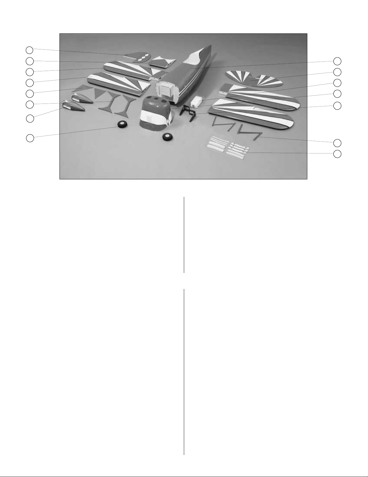
Key # Description Qty
1. FIN with/ RUDDER..........................................(1)
2. TOP WING CENTER SECTION......................(1)
3. BOTTOM WING with/AILERONS .............(2 Pcs)
4. TOP WING with/AILERONS.....................(2 Pcs)
5. LANDING GEAR SPATS ................................(2)
6. PAINTED FIBERGLASS STRUTS .................(2)
7. PAINTED FIBERGLASS WHEEL PANTS ......(2)
8. 4” WHEELS ....................................................(2)
Key # Description Qty
9. FUSELAGE .....................................................(1)
10. STAB with/ELEVATORS ..................................(1)
11. FUEL TANK W/HARDWARE ...........................(1)
12. PAINTED FIBERGLASS COWL ......................(1)
13. ENGINE MOUNT L&R .............................(2 Pcs)
14. PAINTED CABANE STRUTS .........................(2)
15. WING JOINERS ....................................(10 Pcs)
Parts photographed
Kit Contents
Parts not photographed
Page 7
To order replacement parts for the Great Planes Pitts
Special ARF, use the order numbers in the Replacement
Parts List that follows. Replacement parts are available
only as listed. Not all parts are available separately (an
aileron cannot be purchased separately, but is only
available with the wing kit). Replacement parts are not
available from Product Support, but can be purchased from
hobby shops or mail order/Internet order firms. Hardware
items (screws, nuts, bolts) are also available from these
outlets. If you need assistance locating a dealer to purchase
parts, visit www.greatplanes.com and click on “Where to
Buy.” If this kit is missing parts, contact Great Planes
Product Support.
Replacement Parts List
Order Number . .Description . . . . . .How to purchase
GPMA2248 . . . . .COWL Contact hobby
GPMA2249 . . . . .WHEEL PANTS supplier
GPMA2250 . . . . .TOP WING SET
GPMA2251 . . . . .BOTTOM WING SET
GPMA2252 . . . . .FUSE KIT
GPMA2253 . . . . .TAIL KIT
GPMA2254 . . . . .CANOPY
GPMA2255 . . . . .LANDING GEAR
GPMZ0235 . . . . .INSTRUCTION MANUAL
Missing pieces . . . . .Contact Product
Support
Full-size plans . . . . . . .Not available
Before starting to assemble, use the Kit Contents list to
take an inventory of this kit to make sure it is complete.
Inspect the parts to make sure they are of acceptable
quality. If any parts are missing or are not of acceptable
quality, or if you need assistance with assembly, contact
Great Planes Product Support. When reporting defective
or missing parts, use the part names exactly as they are
written in the Kit Contents list on the previous page.
Great Planes Product Support:
Phone: (217) 398-8970
Fax: (217) 398-7721
E-mail: productsupport@greatplanes.com
You can also check our web site at for the latest Pitts
Special updates.
Ordering Replacement Parts
7
Parts not photographed (continued)
(34) #4 x 1/2" WOOD SCREWS (for attaching cabanes to
fuselage, brackets for struts and wires, aileron control
horns, tail gear to fuselage)
(4) 4-40 BLIND NUTS (for attaching wheel pants)
(7) 4-40 THREADED METAL CLEVISES (control surfaces)
(7) 4-40 HEX NUTS (control surface push rods)
(6) 2-56 x 1/2" PHILLIPS MACHINE SCREWS
(for attaching spats to landing gear)
(6) #8 x 5/8" PHILLIPS TRUSS HEAD SCREWS
(for attaching landing gear)
(2) 3-32 WHEEL COLLARS (for attaching tail gear linkage)
(2) WHEEL COLLAR SET SCREW
(for attaching tail gear linkage)
(1) NYLON TORQUE ROD HORN (tail gear linkage)
(1) 2-56 SOLDER METAL CLEVIS
(for attaching tail gear linkage)
(24) ALUMINUM CRIMP TUBES (for attaching flying wires)
(20) 2-56 THREADED BRASS ENDS (drilled for flying wires)
(4) 3/32 [2.4 mm] x 1" [25 mm] x 2" [51 mm] PLYWOOD PLATES
(for mounting wheel pants)
(4) 3/32 [2.4 mm] x 1" [25 mm] x 1" [25 mm] PLYWOOD PLATES
(for wheel pant bearing blocks)
(1) FLYING WIRE
(2) 90-DEGREE COMPOUND BEND BRACKETS
(4) 90-DEGREE BRACKETS
(8) 45-DEGREE BRACKETS
(4) 110-DEGREE COMPOUND BEND BRACKETS
(4) 70-DEGREE COMPOUND BEND BRACKETS
(8) 70-DEGREE BRACKETS
(6) COWL MOUNTING BLOCKS
(for attaching cowl to fuselage)
(2) 3/8" x 1" DOWEL (for bottom wing hold-down)
(10) 4-40 x 1/2" SOCKET HEAD CAP SCREWS
(for attaching top wing to cabanes and interplane struts)
(12) 4-40 x 3/4" SOCKET HEAD CAP SCREWS
(for attaching control horns to elevators and rudder)
(6) 2-56 STOP NUTS
(for attaching spats onto landing gear)
(1) TAIL WHEEL ASSEMBLY
Page 8
❏ 1. If you have not done so already, remove the major
parts of the kit from the box (wings, fuse, cowl, tail parts,
etc.) and inspect them for damage. If any parts are
damaged or missing, contact Product Support at the
address or telephone number listed on page 3.
❏ 2. Remove the masking tape and separate the ailerons
from the wing, the rudder from the fin and the elevators
from the stab. If necessary, tighten the covering with a
covering iron on high heat. Use a covering sock on the iron
to prevent scratches on the covering. Apply pressure over
sheeted areas to thoroughly bond the covering to the wood.
❏ 3. In this manual you will notice boxes placed in front of
each assembly step. These boxes are provided so that you
may place check marks in them as you progress through
the assembly process. If multiple boxes are present, this
step needs to be repeated.
Important note:
The Pitts Special ARF is capable of being
assembled with the option of using four aileron servos. Or
two aileron servos could be used in the bottom wing only,
along with connecting rods between the top and bottom
ailerons. In this manual we will show only the use of four
aileron servos, but extensive testing was performed with the
two aileron servo equipped version. This testing resulted in
very positive response. Even during our very demanding
stress testing, no problems were found.
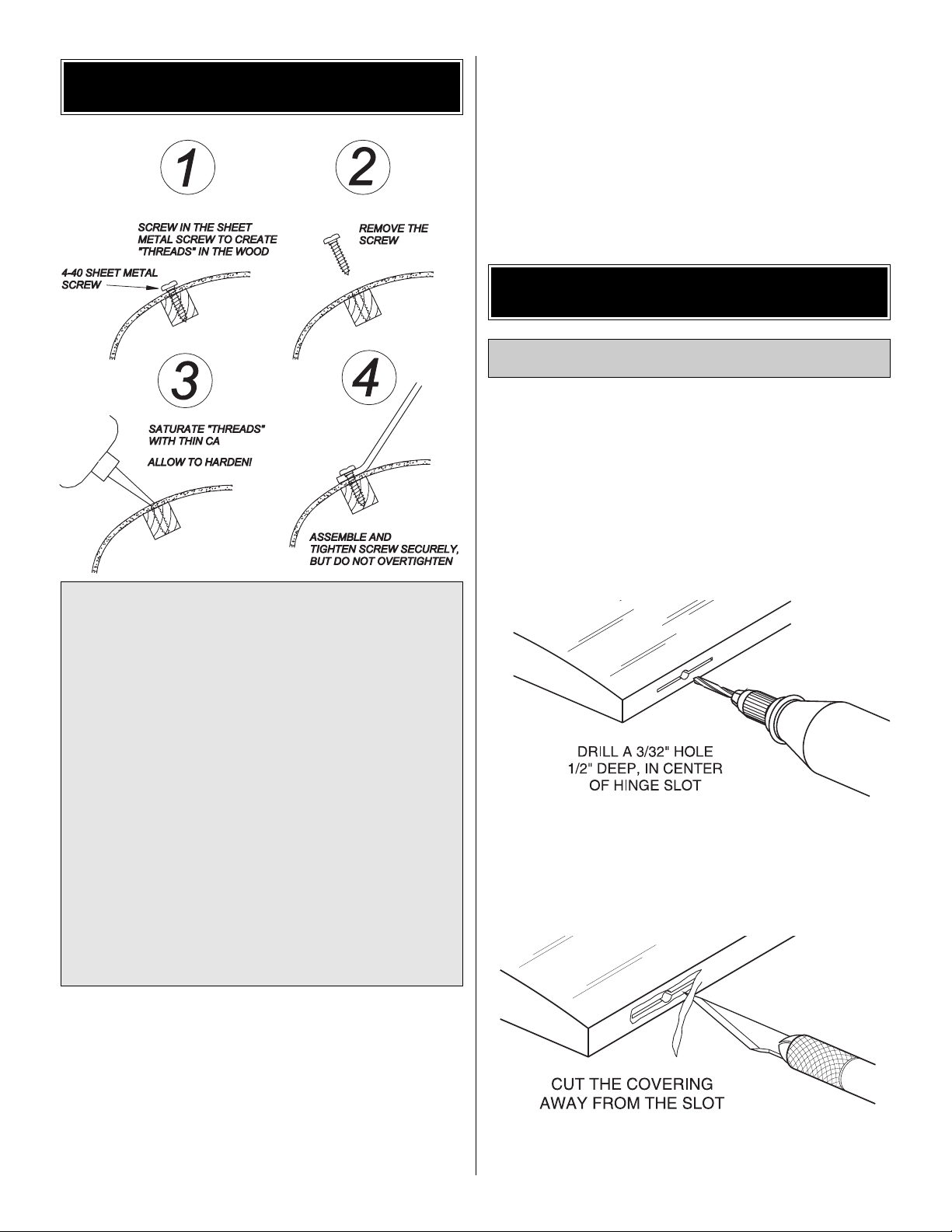
❏ 1. Drill a 3/32" (2.4mm) hole, 1/2" (13mm) deep in the
center of each hinge slot to allow the CA to “wick” in. Followup with a #11 blade to clean out the slots. Hint: If you have
one, use a high-speed rotary tool to drill the holes.
❏ 2. Use a sharp #11 blade to cut a strip of covering from the
aileron hinge slots in all four wing halves and ailerons.
Install the Ailerons
ASSEMBLE THE WINGS
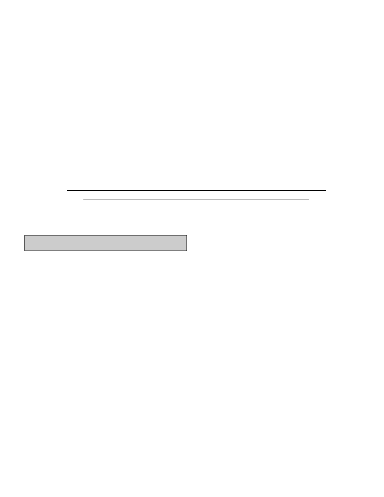
IMPORTANT NOTE: While assembling the Great Planes
Pitts Special ARF, you will encounter a number of areas that
require the installation of various brackets and other items.
Most of the locations for these attachments have predrilled
holes for these applications. The attachment screws do fit
correctly but tightly. We highly recommend that you first drive
the attachment screws into the predrilled holes with a regular
screwdriver, then remove each screw, and thoroughly
saturate the threads you have created in the hardwood with
thin CA. After letting the CA set completely, continue with the
assembly by driving the screws back into the threads you
have created, being careful not to overtighten. Since these
areas are subject to high stress, we strongly recommend
that you DO NOT use an electric or battery powered drill or
screwdriver for this as you can very easily overtighten the
attachment screws and weaken the threads you have
created in the hardwood blocks. Use this technique on all
areas of the model when you attach anything to the model
using screws. Extensive testing of this technique has shown
that this method greatly increases the strength of the model.
PREPARATIONS
8
Page 9
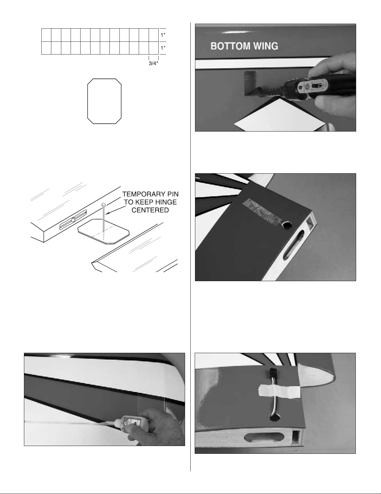
❏ 3. Cut twenty-one 3/4" (19mm) x 1" (25mm) hinges from
the CA hinge strip. Snip off the corners as shown so they
go in easier. Insert three of the hinges into the aileron hinge
slots of each wing half. The rest of the hinges are for the
elevators and rudder.
❏❏❏❏4. Test fit the aileron to the wing with the hinges.
If the hinges don’t remain centered, stick a pin through the
middle of the hinge to hold it in position.
❏❏❏❏5. Remove any pins you may have inserted into
the hinges. Adjust the aileron so there is a small gap
between the LE of the aileron and the wing. The gap should
be just small enough to see light through or to slip a piece
of paper through.
❏❏❏❏6. Apply six drops of thin CA to the top and bottom
of each hinge. Do not use CA accelerator.After the CA has fully
hardened, test the hinges by pulling on the aileron.
❏❏❏❏7. Cut the covering 1/8" (3mm) inside the opening
in this wing half for the aileron servo. Use a trim iron to seal
the covering to the edges of the opening.
❏❏8. Cut the covering away from the hole in the top of the
bottom wing halves and feed the string, which is taped to
the root rib, through the hole in top of the wing. Re-tape it
securely near the hole. This step is different for the two top
wing halves. There is one hole in the center of the top wing
center section. Remove the covering from this hole also.
❏❏❏❏9. Connect a 12" (305mm) servo extension wire
(HCAM2711) to an aileron servo lead and secure it with
9
Page 10
tape or heat shrink material. Tie the string to the aileron
servo extension and pull the wire out of the hole on top of
the bottom wing halves with the string. Tape the connector
to the wing to prevent it from falling back inside the wing.
Then discard the string. The end of the aileron extension in
the top wing halves should be taped to the wing halves until
it is time to join them with the center section of the wing.
This is covered in detail later in this manual.
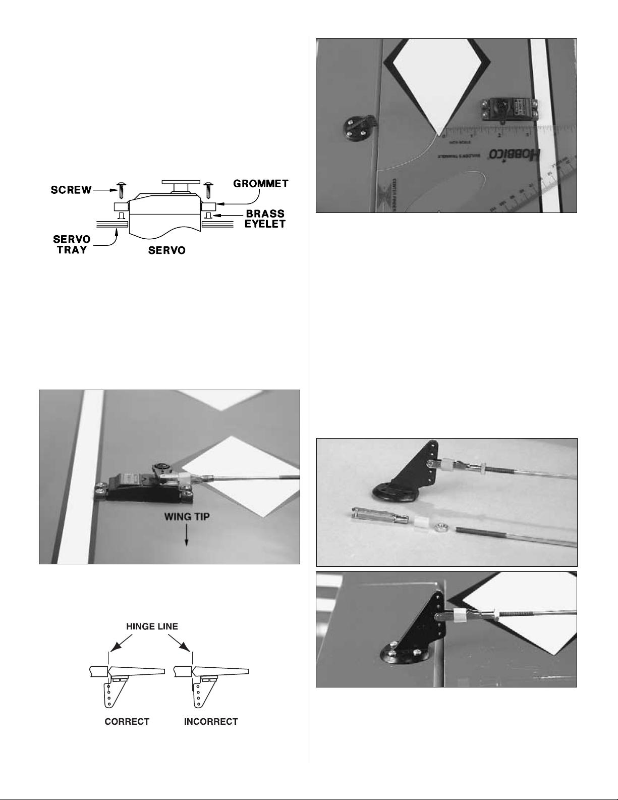
❏❏❏❏10. Insert the grommets and brass eyelets into the
servo as shown. These are included with the hardware
package for the servos. Place the servo into its opening in the
wing half and drill 1/16" (1.6mm) holes in the wing for the servo
mounting screws (also included in the hardware package).
Use the techique shown on page 8 to harden the threads.
Mount the aileron servos using the servo mounting screws.
❏❏❏❏11. The servo arms for the aileron servos are
installed so that they point outboard toward the wing tips as
shown in the above photograph. This is necessary for
proper function.
❏❏❏❏12. Use a builder's triangle to establish a line to
the hole in the servo arm at 90 degrees from the trailing
edge of the wing. At this location use a nylon control horn
as a pattern to mark and drill the four 5/64" (2 mm) holes
1/2" (13 mm) deep into the bottom of each aileron for
mounting the nylon control horns. As shown on page 8, run
the #4 sheet metal screws into the wood. Then remove
them, creating threads in the wood. Saturate these holes
with thin CA, wipe away any residual CA and allow it to fully
harden. Mount the aileron control horns to the ailerons with
four #4 x 1/2" (13mm) sheet metal screws.
❏❏❏❏13. Install a metal clevis, a 4-40 hex nut, and a
clevis retainer on the 4-40 x 12" (305mm) threaded one
end pushrod approximately 15 turns. Remember to use
Great Planes Pro Threadlocker (GPMR6060) on these
clevises and hex nuts after the radio is set up and control
throws have been finished later on in this manual.
10
Page 11
❏❏❏❏14.Place the push rod assembly from step 13 on
the aileron control horn. Center the servo arm on the servo
and align the aileron with the trailing edge of the wing. Place
a 4-40 Metal Solder Clevis onto the servo arm and mark the
location of the push rod as shown in the sketch above with
a felt tip pen. Cut the push rod off at this point and solder
the clevis into place.
NOTE: In the above step you are asked to perform a
soldering task. Please refer to the following tips to make
these solder joints as strong as possible:
❏ 15. Return to step 4 and do the other 3 wing halves.
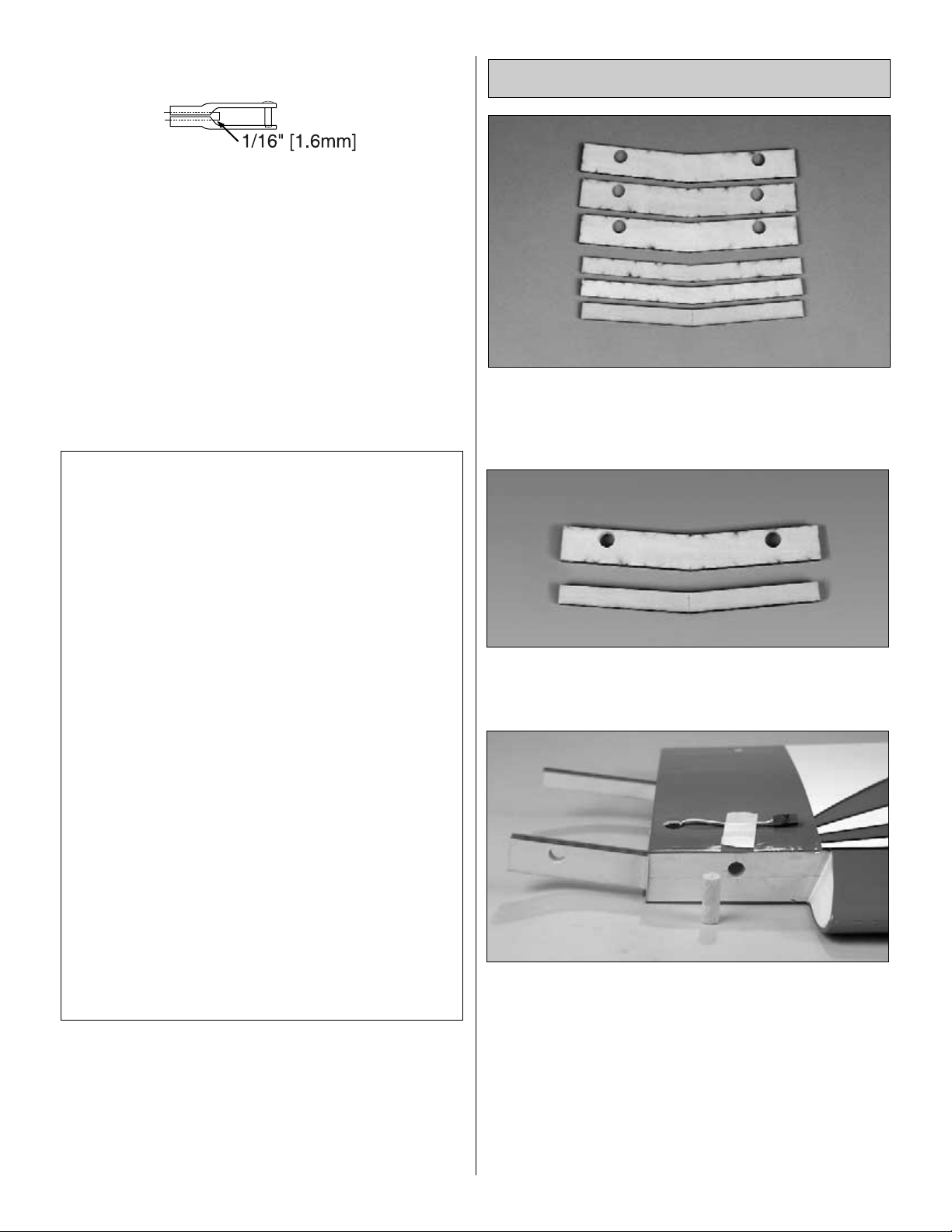
❏ 1. Locate the six die-cut ply wing joiners for the bottom
wing. Note that there are two different sizes of wing joiners
for the front and back of the bottom wing.
❏ 2. Use epoxy to glue the joiners together to form two
plywood joiners as shown.
❏ 3. After the epoxy has cured, sand off any excess glue
and test fit the two lower wing joiners into the two wing
halves as shown above. Note that the two 3/8" (9.5mm)
wood dowels will be placed into the front of the wing. Test fit
them into the wing at this time also. Make sure the wing
halves fit together properly and form a good fitting joint. If
the wing does not fit properly, carefully sand the tips of the
wing joiners until you get the proper fit.
Note: The wing joiners are not designed to fit as tightly as
possible in order to allow epoxy to flow around the joiners
for a more secure and stronger joint.
Join the Bottom Wing
HOW TO SOLDER
A. Use denatured alcohol or other solvent to remove
residual oil from the pushrod.
B. Use coarse sandpaper to thoroughly roughen the end
of the pushrod where it is to be soldered.
C. Apply a few drops of soldering flux to the end of the
pushrod, then use a soldering iron or a torch to heat
it. Coat the end of the pushrod with silver solder
(GPMR8070) by touching the solder to it. The heat of
the pushrod should melt the solder – not the flame of
the torch or soldering iron – thus allowing the solder
to flow.
Note: Do not use silver solder for electrical soldering.
D. Join the clevis to the pushrod. Add another drop of
flux, then heat and add solder. The same as before,
the heat of the parts being soldered should melt the
solder, thus allowing it to flow. Allow the joint to cool
without disturbing it. Avoid excess blobs, but make
certain the joint is thoroughly soldered. The solder
should be shiny, not rough. If necessary, heat the joint
again and allow to cool slowly without disturbing it.
E. After the joint has solidified but while it is still hot,
carefully use a damp cloth to wipe away the excess
soldering flux. Important: After the joint cools, coat it
with oil to protect it from rusting.
11
Page 12
After properly fitting the wing halves together check for the
correct dihedral angle. Place one wing panel on a flat
surface and measure the distance from the elevated wing
tip to the tabletop.This distance should be 5-1/4" (135 mm).
Note: You will need to hang the aileron servo off the edge
of the table in order to get the wing flat on the table as
shown in the sketch above.
❏ 4. When satisfied with the fit and the dihedral angle, use
30-minute epoxy to thoroughly coat the root rib of both wing
halves and the wing joiners. Be sure to apply a generous
amount of epoxy into the inside of each of the wing joiner
pockets. Important: Make sure the joiners are fitted
upright to ensure the proper dihedral. Then, join the wing
halves, holding them together tightly. Use a paper towel,
dampened with alcohol, to wipe away excess epoxy that
comes out of the joint. Securely hold the wing together with
masking tape, making certain both halves are in full contact
and that the leading and trailing edges align. Using the
same 30-minute epoxy, coat the holes in the front of the
wing and the ends of the two 3/8" (9.5mm) wood dowels.
Then, insert them into the front of the wing assembly as
shown, leaving 1/2" (13mm) of the dowel extending from the
wing. You can use rubbing alcohol for any epoxy clean up.
Do not disturb the wing until the epoxy has fully hardened.
❏ 1. If you haven't already, cut the covering away from the hole
in bottom of the top wing center section and feed the string,
which is taped to the sheeting, through the hole in bottom of
the top wing center section. Retape it securely near the hole.
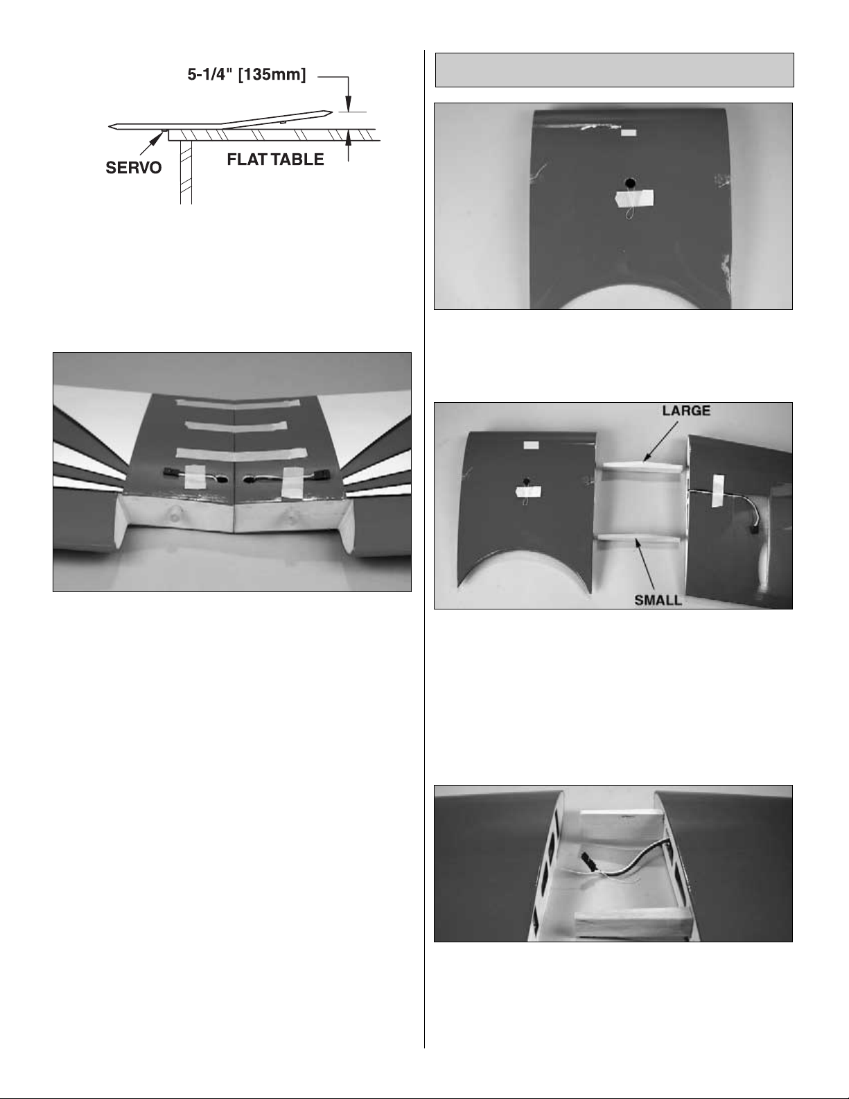
❏❏2. Locate two of the four shaped joiners and test fit the
left wing half and the center section together with the two
shaped joiners in place. Note that you will be using the large
joiner in the front of the wing and the smaller one in the rear
of the wing. Notice the placement of the angles of these
joiners that allows the wing to taper back from the center
section (when positioned properly). Should the fit not be
correct, carefully sand the ends of the joiners to allow a
proper fit. The top wing has no dihedral and is totally flat.
❏❏3. When satisfied with the fit, glue the joiners into the left
wing panel using 30-minute epoxy. Place a generous amount
of epoxy into the inside of the pockets and on the half of the
joiners that will be inserted into the wing pockets. When the
epoxy has cured, tie the string in the center section to the
aileron servo extension wire as shown in the photo above.
Join the Top Wing
12
Page 13

❏❏4. We will now glue the left wing panel and the center
section together as one unit. To do this use 30-minute epoxy
to thoroughly coat the root rib of both the left wing section,
the left outside rib of the center section and a generous
amount in the inside of the wing joiner pockets in the center
section and on the two joiners previously glued into the left
wing panel. Make sure you feed the aileron servo extension
wire into the center section as you slide them together,
being careful not to get glue into the connector as you do.
Hold the center section and the wing section together tightly
with masking tape, making certain they are in full contact
and that the leading and trailing edges align. Wipe away any
excess epoxy and do not disturb the assembly until the
epoxy has fully hardened. Pull the servo extension wire out
of the hole and securely tape it to the center section so it will
not slip back into the hole.
❏ 5. Repeat this process to join the right wing panel to the
assembly of the left wing panel and the center section.
❏ 1. With the fuselage placed upside down, allowing you to
work on the bottom of the aircraft, place the bottom wing
onto the fuselage. Do not secure the wing with the 1/4" x 20
nylon wing bolts yet.
❏ 2. Locate the belly pan and cut the MonoKote from the
two holes which allow access for the wing bolts. Saturate
the exposed wood with thin CA to make it stronger, and
paint this area after the CA has cured to make it fuel proof.
❏ 3. Place the belly pan on the bottom of the lower wing
allowing it to center over the wing bolt holes (you may want to
install the wing bolts to hold the belly pan in place as shown in
the photo) and also match up to the bottom of the fuselage in
front and behind the wing. When satisfied with the fit, mark the
outline with a Top Flite Panel Line Pen (TOPQ2510).
❏ 4. Using a Hobbico Hot Knife (HCAR0770), cut only the
covering and NOT the underlying wood 1/8" (3 mm) inside
the outer lines so that the covering will extend under the
edge of the belly pan when you glue it on.You may also use
a hobby knife with a #11 blade. Be sure to do this step
gently as both of these methods can result in cutting into the
wood under the covering which will weaken the structure if
not done carefully. The Hobbico Hot Knife, as mentioned
above, will allow you to cut the MonoKote using the least
amount of pressure due to the heat helping to cut through
the covering.
❏ 5. After removing the covering use epoxy to glue the belly
pan to the wing. Allow the epoxy to cure completely. Be very
careful not to get glue into the area where the belly pan fits
into the fuselage; glue it only to the wing itself.
Mount the Bottom Wing
ASSEMBLE THE FUSELAGE
13
Page 14

Note: Throughout the rest of the assembly process you
will be installing different types of metal brackets. These
are diagrammed below. Pay close attention to each metal
bracket to make sure you are using the correct one for
each particular application and that they are oriented as
shown in the photographs. Also note that the holes in
each bracket are of a different size. The larger hole allows
the mounting screw to pass through and the smaller hole
is for attachment of the metal clevis.
❏ 1. Locate the four predrilled holes in the bottom of the top
wing center section.
IMPORTANT NOTE: IN THE FOLLOWING STEP IT IS VERY
IMPORTANT TO INSTALL THE TWO 90-DEGREE
BRACKETS PROPERLY. THESE BRACKETS HAVE ONE
SIDE THAT IS LONGER THAN THE OTHER. WHEN
INSTALLED CORRECTLY THERE SHOULD BE NO GAP
BETWEEN THESE BRACKETS. IF THERE IS A GAP THEY
ARE INSTALLED WRONG. CHECK THE PHOTOGRAPH
ON PAGE 15, STEP 8 FOR THE PROPER POSITION OF
THESE BRACKETS.
❏ 2. Using the technique described on Page 8, install two
90-degree metal brackets (Bracket D, as shown above) into
the pre-drilled holes in the front of the bottom of the top wing
center section with two #4 x 1/2" (13mm) wood screws.
Mount two 90-degree compound bend metal brackets
(Bracket C, as shown above) using two #4 x 1/2" (13mm)
wood screws. The cabane struts and flying wires will attach
to these "C" brackets in a later step.
❏ 3. Next locate the four predrilled holes in the two outer
panels of the bottom of the top wing just outboard of the
aileron servos.
❏ 4. Again, using the technique described on Page 8, install
the four 70-degree compound bend metal brackets (Bracket
A, as shown in the diagram) in place (two on each wing
panel) with four #4 x 1/2" (13mm) wood screws as shown in
the photo above. The orientations of these brackets are
shown in the photograph.
Mount the Top Wing
14
70˚
Compound
Bend Bracket
110˚
Compound
Bend Bracket
90˚
Compound
Bend Bracket
90˚ Bracket
70˚ Bracket
Page 15

❏ 5. Next locate the four predrilled holes in the outer panels of
the top of the bottom wing. See the exact locations and
orientations of the brackets in the following two photographs.
❏ 6. Again, using the technique described on Page 8, install
the four 110-degree compound bend metal brackets
(Bracket B as shown above) in place with four #4 x 1/2"
(13mm) wood screws as shown in the photos above.
❏ 7. Locate the two painted metal cabane struts. Temporarily
and loosely place two 4-40 x 1/2" (13 mm) Socket Head Cap
Screws through the holes in the top of the cabane struts and
hold them both together with two 4-40 Nylon Stop Nuts. Do not
tighten them at this time. Make sure that you have the
orientation of the cabanes correct as shown in the
photographs. Locate the four predrilled holes in the top of the
fuselage. Again, using the same technique described on
page 8 that you used for attaching the wing brackets, install the
cabane assembly exactly as shown in the photographs above
using four #4 x 1/2" (13mm) wood screws.
❏ 8. Attach the top wing by first removing the two temporary
4-40 x 1/2" (13mm) Socket Head Cap Screws from the top
of the cabane struts and re-inserting them through one
cabane strut hole. Then continue through the two 90 degree
brackets mounted in the top wing, and then back through
the remaining cabane hole. Next, install 4-40 nylon stop
nuts onto the 4-40 x 1/2" (13mm) Socket Head Cap Screws.
Notice in the above photograph that the cabane struts fit on
the outside of the two 90-degree brackets. Do this for both
mounting points.
❏ 9. Locate the two interplane struts; note that there is a left
and right. This is determined by the contour angles on the
top and bottom of each interplane strut, which allow them to
fit properly against the wing.
With the bottom wing still attached to the fuselage, position
the struts on the outboard sides (toward the wing tips) of the
70-degree compound bend metal brackets on the bottom of
the top wing and the 110-degree compound bend metal
brackets on the top of the bottom wing.
❏ 10. For location of the interplane struts on the bottom
wing, measure from the TE of the aileron to the rear tip of
15
Page 16

the bottom of the interplane strut. This distance is 3-¼"
(83mm). When satisfied with the position, mark the location
for the two holes in the bottom of the interplane struts.
Remove the interplane struts and drill these two holes with
a 1/8" (3 mm) drill bit. Saturate these two holes with thin CA.
When the CA is set, secure the strut using two 4-40 x 1/2"
(13 mm) socket head cap screws, two 4-40 washers, and
two 4-40 nylon insert stop nuts. Make sure it is tight, but not
overly tight. Repeat this process for the remaining strut.
❏❏11. The placement of the struts in relation to the top
wing is determined in the following manner. Measure the
distance of the top rear tip of both interplane struts to the
trailing edge of the top wing. If necessary, twist the top wing
in order to make both distances equal. When satisfied with
the alignment, mount the top of the interplane struts to the
brackets installed in the top wing using the same method as
the bottom of the interplane struts.
❏ 1. Cut and remove the MonoKote covering from the
opening in the rear of the fuselage for the horizontal stab
and the fin.
❏ 2. Locate the horizontal stab. Find the center by
measuring from tip to tip of the stab. At this point mark a
centerline at a 90-degree angle from the trailing edge of the
stab to the leading edge. Trial fit the stab into the stab
saddle. Check the position of the stab by measuring the
distance from the center of the fuse at the tail post to each
tip of the stab; this distance needs to be the same. Make
adjustments as needed until the distance is equal by
moving the "long" tip in the opposite direction half the
distance it was too long.
❏ 3. With the wings still attached, place the model in a
building stand such as a Robart Super Stand II
(ROBP1402). Place a T-pin on the center line of the fuse at
the forward most former. Measure from the pin to each tip of
the stab. A Hobbico Retractable Fabric Tape Measure
(HCAR0478) works well for this step. The distance from the
pin to the stab tips needs to be equal on both sides.
❏ 4. Stand ten to fifteen feet behind the model and view the
stab and wings. If the stab and wings align with each other,
proceed to the next step. If the stab and wing do not align,
remove the stab and carefully sand the "high side" of the slot
in the fuse where the stab fits until the stab aligns with the
wing. If you needed to make any adjustments, reposition the
stab into the fuselage, making sure the alignment is correct.
❏ 5. Using a felt-tipped pen, carefully mark the location of
the fuse sides on both the top and bottom of the stab.
Remove the stab from the fuselage and cut 1/8" inside the
line in order to remove the MonoKote covering from the
stab. Use a hot knife or sharp hobby knife with the same
Mount the Stab and Fin
16
Page 17

technique that was used while adding the belly pan onto the
bottom wing. Again, be careful not to cut into the wood while
removing the MonoKote.
❏ 6. Slide the stab back into the fuselage, leaving the
exposed wood outside of the fuselage joining area.
Note: This will be a little messy but the epoxy will clean up
easily and will allow you to obtain a strong joint of the stab
to the fuselage. Apply 30-minute epoxy to the top and
bottom of the exposed wood on the stab. Slowly work the
stab into the fuselage to a point 1" (25 mm) beyond the first
cut-line to appear on the other side of the fuselage. Since
the fit of the stab into the fuselage is tight, doing this will
push some of the epoxy back.Wipe away this excess epoxy.
Apply more epoxy to the exposed wood on the stab where
you pushed it past the center position and slowly move it
back into place after doing so. Carefully re-position the stab
into proper alignment. Using a paper towel, wipe away the
excess epoxy. Using a generous amount of denatured
alcohol on a paper towel, clean any epoxy residue from the
model, but do not allow an excess amount of alcohol to flow
into your joint. Also check the bottom of the fin slot on top of
the fuselage to make sure you do not have an excess
amount of epoxy in the area on top of the stab. The fin
needs to fit securely and properly into this area. Allow the
epoxy to thoroughly cure before moving the model.
❏ 7. Trial fit the fin to the fuse. Use a triangle like the
Hobbico Builders Triangle (HCAR0480) to make sure the fin
is 90 degrees square to the stab. When satisfied that the fit
and alignment are correct, mark the location of the fuse
onto the fin. Carefully remove the MonoKote covering 1/8"
inside these lines using the same method used on the stab.
Apply a generous amount of 30-minute epoxy to the fin slot
sides and the top of the stab at the bottom of the slot. Insert
the fin into the slot and as with the stab remove any excess
epoxy and residue. Using your triangle, re-check for the
correct alignment in relation to the stab. Allow the epoxy to
completely cure before proceeding.
❏ 8. To attach the elevators, drill a 3/32" (2.4mm) hole, 1/2"
(13mm) deep in the center of each hinge slot to allow the
CA to “wick” in. Follow up with a #11 blade to clean out the
slots and cut a strip of covering from the hinge slots in the
stab and elevators.
❏ 9. Install the hinges into the stab and then test fit both of
the elevators. If the hinges don’t remain centered, stick a
pin through the middle of the hinge to hold it in position.
❏ 10. Remove any pins you may have inserted into the
hinges. Adjust the elevator so there is a small gap between the
LE of the elevator and the stab.The gap should be small — just
enough to see light through or to slip a piece of paper through.
❏ 11. Apply six drops of thin CA to the top and bottom of
each hinge. Do not use CA accelerator. After the CA has
fully hardened, test the hinges by pulling on the elevators.
❏ 12. To attach the rudder drill a 3/32" (2.4mm) hole, 1/2"
(13mm) deep in the center of each hinge slot to allow the
CA to “wick” in. Follow-up with a #11 blade to clean out the
slots and cut a strip of covering from the hinge slots in the
fin and rudder. Trial fit the hinges into the rudder and place
onto the fin. The gap should be small—just enough to see
light through or to slip a piece of paper through.
❏ 13. Apply six drops of thin CA to each side of each hinge.
Do not use CA accelerator. After the CA has fully hardened,
test the hinges by pulling on the rudder.
17
DRILL A 3/32" HOLE
1/2" DEEP, IN CENTER
OF HINGE SLOT
Page 18

❏ 1. Cut the covering 1/8" (3mm) inside the opening in the
fuselage for the two elevator and one rudder servos. Use a
trim iron to seal the covering to the edges of the opening.
When cutting the covering from the servo bays, refer to the
photograph in STEP 8 on PAGE 19 for proper placement of
servos. Cut the covering from two servo bays on the right
side of the fuselage. On the left side of the fuselage cut only
the covering from the servo bay closest to the stab. Note:
You can place your rudder servo on either side of the fuse
as a servo bay is provided on both sides. Do not cut the
covering from both sides unless you intend to use two
servos for the rudder.
❏ 2. Place the grommets and brass eyelets onto your
servos as shown in the sketch above. Depending on your
choice of radio operation, connect either a 12" (305mm)
servo extension wire (HCAM2711) or if using a Y-Harness
(HCAM2751) connect it to one elevator servo, secure it with
tape or heat shrink material, and place the servo into the
servo bay. Run the remaining end of the Y-Harness through
the opening and connect it to the second elevator servo,
secure it with tape or heat shrink material, and place the
servo into the servo bay.
❏ 3. With the servos in position in the fuselage, drill 1/16"
(1.6mm) holes in the fuselage for the servo mounting
screws. Using the technique described on Page 8, mount
the elevator servo using the supplied screws.
❏ 4. Position the elevator control horns directly in line with the
servo arms and with the hinge alignment as shown above. At
both locations mark and drill the four 1/8" (3mm) holes for
each of the horns. Saturate these holes with thin CA, wiping
away any residue and allow it to fully harden. Then re-drill the
holes to allow the screws to pass through easily. Mount the
control horns and back plates to the two elevators with eight
4-40 x 3/4" (19mm) socket head screws.
❏ 5. Install two 4-40 threaded metal clevises, two 4-40 hex
nuts, and two clevis retainers onto two 12" (305mm) 4-40
pushrods approximately 15 turns. Attach these two push
rod assemblies to the control horns. Attach two 4-40 solder
clevises to the two elevator servo arms.
❏ 6. Center the servo arm on the servo and align the
elevators with a straight edge. Holding the push rod assembly
and the 4-40 Metal Solder Clevis on the servo arm in place,
mark the location of the push rod as shown in the sketch
above with a felt tip pen. Cut the push rod off at this point and
solder the clevis into place. Repeat this procedure for the
remaining elevator and also for the rudder servo.
Important: The installation of the two elevator servos
presents a number of options that you must consider at
this time as it does affect the manner in which you must
mount these two servos. If you are using a radio system
that is capable of setting up the two servos on different
channels and then mixing them together for the elevator
operation (see your radio system manual), you must
mount both servos in the same direction with the servo
arms placed in the same direction. This would also apply
if you used one reversed servo. Another option, and
probably the best, is the Futaba SR10 / Dual Servo
Synchronizer and Reverser (FUTM4150). The SR-10 is
also compatible with the majority of other R/C
manufacturer’s systems.
If you plan to use a simple Y-harness system for both
elevator servos you must make sure that your servos are
mounted in the same direction but with the servo arms
pointing in opposite directions.
Install the Servos
18
Page 19

❏ 7. The photo above references the completed installation
of elevator and rudder servos, control horns, and pushrods.
Looking forward from the rear of the fuselage you can see
that the rudder servo is placed below the elevator servo.
❏ 8. To install the tail gear, position it so the forward edge
is 4-1/2" (115 mm) from the aft end of the fuselage as
shown in the above photo. Mark the location of the holes in
the tail gear on the fuselage and drill two 3/32" (2.4 mm)
holes. Be sure to again use the method of installing screws
into the model described on page 8 and install the gear with
two #4 x 1/2" (13 mm) Phillips head wood screws.
❏ 9. Grind or file a flat spot on the tail wheel wire where the
steering arm will be located. To locate its proper position
align the tail wheel with the rudder and mark the tail wheel
wire 90 degrees from the tail wheel. Assemble the tail gear
by placing one of the 1/8" (3mm) wheel collars and 4-40
setscrew onto the vertical wire portion of the gear. Then slip
it into the tail gear bracket. Attach the steering arm onto the
wire on the top side of the bracket as shown in the photo.
The steering arm must face the side of the fuse where the
rudder servo is located and be at 90 degrees to the tail
wheel. Install the tail wheel and the two 1/8" (3 mm) wheel
collars onto the gear. File flat spots on the gear wire and be
sure to use Threadlocker on all the wheel collar set screws
during the final assembly, to prevent them from loosening.
❏ 10. In order to make the ground steering as positive as
possible we are using a 2-56 pushrod extended from the
rudder control rod to the tail wheel steering arm. This is
shown in the above photograph. It is assembled by first
removing the rudder pushrod, metal clevis, clevis retainer
and hex nut from one end of the assembled pushrod.
❏ 11. Place a 3/32" wheel collar onto the rudder pushrod and
secure it into place with the set screw 1-1/4"(32mm) back from
the clevis where it enters the servo arm. On any high
performance model, always secure set screws with
Threadlocker. Cut two lengths of fuel line 1/2"(13mm) long. Slip
one piece of the fuel line onto the rod. Next slip the torque rod
control arm onto the rod as shown, followed by the remaining
piece of fuel line. Place another 3/32" wheel collar into place
behind the last piece of fuel line and secure it with the set
screw. Replace your hex nut and metal clevis and reattach the
assembly onto the rudder servo and control horn.
❏ 12. Place a nylon clevis onto the 2-56 x 12" (305mm)
threaded one end push rod approximately 25 turns and add
a silicone clevis retainer to it. Make a bend in the rod as
shown to align with the steering arm. Attach a 2-56 metal
solder clevis to the steering arm and hold it and the push rod
assembly in place while you align the tail wheel with the
rudder. Make a mark on the rod just as you did with the
rudder and elevator push rods. Cut the rod at that location
and solder the clevis into place. Attach the rod in place as
shown in the photos. This completes the tail wheel assembly.
19
Page 20

❏ 1. To mount the main landing gear set it into place using
the above photograph for the proper orientation and mark the
location of the six holes drilled in the landing gear on the
landing gear plate. Using the technique described on Page 8,
mount the landing gear using the six # 8 x 5/8" (16 mm) truss
head screws.
❏ 2. Place the landing gear cover on top of the landing
gear itself and press on it firmly in order to mark the location
of the six truss head screws. Using a drill or a rotary tool,
make clearance holes for the heads of the six screws. You
may glue this cover into place or attach it with landing gear
straps in order to retain access to the landing gear and its
hardware if you wish.
❏❏3. Position the landing gear spats onto the landing
gear. Carefully align the leading edge of the spat with the
leading edge of the landing gear. Drill the 3/32"(2.4mm)
holes through the spats and the landing gear in the
locations shown in the above photograph. Use three 2-56 x
1/2"(13mm) Phillips head bolts, three #2 flat washers, and
three 2-56 lock nuts to secure the spats. The 90-degree
bracket is to attach the flying wires and is mounted in the
location shown in the above photograph. Repeat this step
for the remaining side of the landing gear.
❏❏4. Look closely at the painted fiberglass wheel pants
and you will notice there is a mark which indicates the
correct position for the 5/32"(4 mm) hole to be drilled to
allow the axle shafts to pass through.
Important: You must make one right and one left wheel
pant so make sure that you drill the holes on the inboard
side of both pants. DO NOT drill holes in both sides of the
wheel pants.
Mount the Landing Gear
20
Page 21

❏❏5. Locate the four 3/32"(2.4 mm) x 1"(25 mm) x 2"(51 mm)
plywood doublers for mounting the wheel pants and the four
3/32"(2.4 mm) x 1"(25 mm) x 1"(25 mm) plywood wheel pant
bearing blocks. Make two sets as shown in the above
photograph by gluing them together using 6-minute epoxy.
Position the large doubler centered over the hole you drilled
previously in the wheel pant. When satisfied with the
location, mark its position and rough up the fiberglass with
80 grit sand paper. Then glue it into place using 30-minute
epoxy. When the epoxy has cured, drill another 5/32"(4 mm)
hole through the plywood doubler using the hole in the
wheel pant as a guide.
❏❏6. Use a rotary tool or a drill to carefully create a
7/16"(11.1mm) clearance hole in the fiberglass wheel pant
and plywood doubler as shown in the above photo for the
axle unit base to fit into. Do not make this hole deeper than
9/64" (3.6 mm).
❏❏7. Mark the location of the center of the plywood wheel
pant bearing block you prepared earlier as shown in the
photograph and drill a 5/32" (4mm) hole at this location.
Slip the 5/32" x 2" axle through the wheel pant and place
the bearing block over the axle shaft. Hold the block in place
against the outboard side of the wheel pant so that the
wheel pant is level and straight. Mark the location of the
block on the inside of the wheel pant. Rough up the
fiberglass with 80-grit sandpaper and glue the block into
place with epoxy. DO NOT DRILL THROUGH THE WHEEL
PANT AT THIS LOCATION.
❏❏8. Install the axles onto the landing gear, making sure
the stop nuts are securely tightened.
❏❏9. Temporarily place the wheels into the wheel pants
and slip them onto the axle shaft. As shown in the above
photograph, set the model on a flat surface and position the
aft end of the wheel pants 1" (25mm) above the surface.
Mark the locations, on the wheel pant, of the two holes
drilled in the landing gear while the aft end of the pants are
still elevated 1" (25mm) off your flat surface.
Remove the wheel pant from the landing gear and drill 1/8"
(3mm) holes at the marked locations. Epoxy two 4-40 blind
nuts into these holes inside the wheel pant but be careful
not to get the glue into the threads.
21
Page 22

❏❏10. Insert the axle shaft through the wheel pant and
plywood doubler while at the same time slipping one 5/32"
wheel collar with a 6/32" setscrew installed onto the shaft.
❏❏11. Next fit one of the supplied wheels onto each shaft
followed by another 5/32" wheel collar with a 6/32" setscrew
installed. Center the wheels within the wheel pants and
temporarily tighten the 6/32" setscrews in the wheel collars
to hold them in place.
❏❏12. Install the 4/40 x 5/8" (15.9 mm) Phillips Head
Machine Screws through the holes in the landing gear and
into the blind nuts installed inside the wheel pant.
❏❏13. The photograph above shows the assembly of the
wheels and pants. Mark the axle for location of the wheel
collars. Remove everything from the axle and grind flat
spots on the axle for securing the wheel collars. After doing
this, reassemble the wheels and pants with the wheel
collars, making sure they are tightened properly with
Threadlocker applied. Align the wheel pants to their proper
position and insert the two 4-40 x 5/8" (15.9 mm) Phillips
Head Machine Screws through the holes in the landing gear
and into the blind nuts in each wheel pant securing them to
the landing gear.
❏ 14. Repeat this process for the remaining wheel and pant.
Note: The following instructions are for the installation of a
glow engine. If you are using a gas engine go to page 24.
❏ 1. Notice the marks on the firewall. Extend the horizontal
and vertical lines with a pen to see them more clearly as
shown in the photo above. Disregard any other marked
lines on the firewall.
Mount the Engine
22
Page 23

❏ 2. After removing the spreader bars from both engine
mount halves, fit the two halves together using the engine
to space the width properly. Notice that when you find the
proper width for your engine, the tick marks on the two
halves of the engine mount will no longer line up with each
other. Measure the distance between the two tick marks and
mark the center location between these tick marks. This
location will be used to properly align the engine mount with
the firewall markings.
Being careful not to move the width of the engine mount,
position the engine mount onto the firewall using the tick
marks and the marks you just made on all four sides of the
mount to align it with the horizontal and vertical lines on the
firewall. Mark the location of the holes with a Dead Center
Hole Locator (GPMR8130).
❏ 3. Drill four 7/32" (5.6mm) holes through the firewall at the
marks. Apply 30-minute epoxy to the four 8-32 blind nuts,
being careful not to get the glue into the threads and place
them into the holes on the back of the firewall. Attach the
engine mount to the firewall with four 8-32 x 1" (25mm)
socket head cap screws and #8 flat washers. This will draw
the blind nuts into the back of the firewall. Allow the epoxy
to cure.
❏ 4. Position the engine on the mount so the engine drive
washer is 6-1/2" (165mm) from the firewall.This will provide
the correct clearance between the spinner and the cowl.
❏ 5. Using your Dead Center Hole Locator again, mark the
hole locations on the engine mount. Drill #29 (or 9/64")
holes through the engine mount at the marks you made,
then tap 8-32 threads into the holes. Mount the engine to
the mount with four 8-32 x 3/4" Socket Head Cap Screws
and #8 washers.
❏ 6.Test fit the muffler to be used on your engine.The O.S.
1.60 FX (OSMG0661) is shown in this manual. Bisson
Custom Mufflers produce a Pitts Style Muffler (BISG4116)
that is designed specially to fit this engine and is shown in
the photo above.
23
Page 24

❏ 7. Attach a 12" servo extension to the throttle servo and
use tape or heat shrink material to secure it in place. Insert
the servo lead into the hole in the former located inside the
engine-mounting box. Place the servo, noting its orientation
in the photograph above, in the pre-cut space on the bottom
of the engine mount box as shown in the photo. Using the
same techniques shown on page 8, mount the servo by
drilling four 1/16"(3mm) holes using the hardware that came
with the servo to secure it into place.
Make the throttle pushrod from the supplied 2-56 x 17-1/2"
(466 mm) threaded one end throttle pushrod. Thread a nylon
clevis onto the threaded rod approximately 25 turns, add a
clevis retainer, and attach the clevis to the throttle arm on the
carburetor on the engine. Make necessary bends in the rod to
allow it to clear the engine and muffler. Then connect it to the
throttle servo arm by making a 90-degree bend and using a
nylon Faslink connector to secure it into place.
NOTE: This model will accept a number of different
engines including gasoline-powered engines. We have
just gone through the process of mounting a typical twostroke engine in the previous steps. We will now go
through the process of mounting a gas engine, using the
US Engines 41cc 2.5 Gas Engine (USEG0041). Notice that
the drive washer of any engine should be placed 6-1/2"
(165 mm) forward of the firewall.The use of some engines
may require alterations of the engine mounting box.
❏ 1. Since this engine mounts with bolts from the rear of a
traditional firewall, we will make a plywood mount to be
attached to the engine. After this mount is attached to the
engine it will then be mounted to the existing firewall. First
of all make two 4" [102mm] x 4" [102mm] x 1/4" [6 mm]
plywood mounting plates [not supplied]. Draw center marks
on one of these plates as shown above. This plate will be
used as the front half of your mount. Do not glue these
pieces together at this time.
❏ 2. Place the front side of the front plate (the one with the
center marks) against the back of the engine and mark the
location of the mounting holes with the engine centered on
the mount. Also draw the outline around the back of the
engine as shown in the photograph. Note: Depending on
the muffler used you may need to relieve a portion of the
mount to accommodate your muffler. Drill 1/4" [6mm] holes
in these four locations through both plates.
24
Page 25

❏ 3. Place the four 1" (25 mm) x 1/4" (6 mm) x 20 engine
mounting bolts (not supplied) into the rear plate. Place a
socket that fits these bolts over the bolt heads and draw a
line around all four as shown in the above photograph.
Remove the wood from inside these four marks on the rear
plate only. Doing this will allow the socket to fit inside the
rear plate and countersink the bolt heads when the two
halves are assembled.
❏ 4. The existing firewall on the model has centering marks
on the face of the firewall. Highlight and extend these lines
with a felt tipped pen as shown in the above photograph.
❏ 5. Glue the two halves of the plywood mount together
using epoxy. Make sure that you assemble the two halves
with the center marks and engine outline on the front. Clamp
or add weight to the assembly and allow the epoxy to cure
completely. Saturate the 1/4" (6 mm) holes with thin CA.
Place the assembly onto the firewall and line up the
centering marks on the mount and the firewall. Mark four
locations at which you will place 8-32 x 1" (25 mm) socket
head cap screws and 8-32 blind nuts to secure the mount to
the firewall. Check the spacing between the location of the
engine and the edge of the mount. Drill 3/16" (4.8 mm) in
these four locations. Again, hold the mount in place on the
firewall and mark the locations of these holes on the firewall.
At these four marked locations drill 7/32" (5.6 mm)
clearance holes for the blind nuts.
❏ 6. Install the four 8-32 blind nuts in the firewall in the
holes you just drilled. Install the mount onto the engine with
the four mounting bolts through the mount and into the back
of the engine. Next mount the engine to the firewall using
the four 8-32 x 1" (25 mm) socket head cap screws.
❏ 7. Mark the location for the throttle push rod (the supplied
throttle pushrod will not be long enough for this purpose)
and drill a 1/8" (3 mm) hole through the mount, firewall and
the front former.
Note: Be very careful to avoid the area where the gas tank
will be placed. Decide where you want to locate the throttle
servo and make a plywood mount for it at that location.
Note: If the throttle servo mount will interfere with the
installation of the gas tank, move to the next section and
install the tank before installing your throttle servo. Be sure
25
Page 26

to install your servo properly using the same procedures
that you used previously.
We recommend that prior to finalizing your engine mounting,
remove the engine and the mount. Use epoxy or finishing resin
to coat the mount to protect it from oils and gasoline residue.
After the epoxy or resin has cured, re-assemble the engine and
mount. Then mount it permanently onto the firewall. We also
recommend that you use Threadlocker on all engine mounting
bolts. At this point go back to the 2-cycle glow engine
instructions and continue with any necessary steps there to
complete your gas engine installation.
Important Note: The fuel tank supplied with this model is
not set up for gasoline use.You will need to use the proper
equipment and set-up that is compatible.
❏ 1. Assemble the fuel tank. Arrange the stopper and tubes
as shown in the photo, then fit them into the tank. Tighten
the screw to expand the stopper, thus sealing the tank. Be
certain the fuel line weight (clunk) at the end of the fuel line
inside the tank does not contact the rear of the tank.
Otherwise, the line may become stuck during flight and
discontinue fuel flow. Remember (or use a felt-tip pen to
mark) which tube is the fuel pick-up tube and which tube is
the vent (that will be connected to the pressure fitting on the
engine muffler).
❏ 2. Install the fuel tank so the neck fits through the existing
hole in the former behind the engine-mounting box. Be certain
that you have installed the tank so the vent tube inside the tank
is pointing upward. Notice in the above photograph that the
former has been designed to allow rubber bands to hold the
tank in place. However, due to the aerobatic potential of this
model aircraft, we strongly advise that you also secure it in
place with silicone or epoxy. Note: There is a hole in the
bottom of the engine mounting box for the purpose of
routing the fuel lines through.
❏ 3. Run the fuel line to the needle valve or if you are using an
Easy Fueler Valve (GPMQ4160) as shown in the photograph
above, attach the fuel line to the valve first and then the needle
valve. Attach the vent line to the pressure tap on the muffler.
The Easy Fueler Valve can be mounted easily by using a Great
Planes Handy Mounts (GPMQ6000) which is also shown in
the photograph.
❏ 1. Mark the location of the six cowl mounting blocks on
the forward fuselage former as shown in the photograph
above. Using 80-grit sandpaper, rough up the surface in this
area in order to allow a better glue joint. Use epoxy to glue
the six cowl mounting blocks to the front of the fuselage in
the locations shown in the above photograph. After the
epoxy cures, fuelproof these blocks using additional epoxy.
Mounting the Cowling
Assemble & Install the Fuel Tank
26
Page 27

❏ 2. After the epoxy has cured cut a piece of a file folder,
index card, or any similar material and securely tape it to the
side of the fuselage so that it covers one of the mounting
blocks. Find the center of the mounting block and place a
mark on the card taped to the fuselage.
❏ 3. Place the cowl on the fuselage in the correct
alignment and allow the engine drive washer to extend past
the front of the cowl at least 1/8" (3mm). When satisfied with
the alignment, tape the cowl in place and drill a 1/16"(1.6
mm) pilot hole through the cowl and the mounting block at
the location you marked on the card stock taped to the
fuselage. Enlarge the 1/16"(1.6 mm) hole in the cowl for
clearance with a 3/32"(2.4mm) drill bit to allow the #2 x 1/2"
(13mm) Phillips head screws to pass through the cowl.
Do not redrill the pilot hole in the cowl mounting blocks.
❏ 4. Repeat this process at the locations of the other five
cowl mounting blocks. Mount the cowl using six #2 x 1/2"(13
mm) Phillips head screws and six #2 flat washers.
❏ 5. You will need to cut other access holes in the cowling
for things like the fueling valve, needle valve, and glow
driver access to start the engine. Use this same method to
locate these holes. When finished you will have accurate
locations for these functions.
❏ 1. The aluminum spinner supplied with this model is a new
and innovative design, which is universal and eliminates the
need for adapter nuts. To assemble the spinner, hold the
backplate and propeller (not supplied) together as one unit and
place onto the drive shaft.
Assemble and Install the Spinner
27
Page 28

❏ 2. Place the drive washer and the propeller nut onto the
drive shaft. Tighten the nut securely with a box-end wrench
of the correct size to fit your engine. Next install the lock nut,
again with a box-end wrench.
❏ 3. Place the spinner cone over the blades of the propeller
and secure it with the supplied bolt.
❏ 1. The radio system installation is very simple; we have
already installed all the servos on the exterior of the aircraft
so there is very little to be placed inside the fuselage. To
power the system and the maximum of eight servos we
used a Futaba®NR4RB 4.8V 1000mAh battery pack
(FUTM1380) in all our test models. In order to keep the
weight as far forward as possible, the battery was mounted
just behind the most forward former.
Included with the model is a ply tray that can be installed
behind the fuel tank to hold the battery pack and receiver if
you wish to use that method.
❏ 2. To mount the receiver we used a Great Planes
Receiver Guard Protective Case (GPMM1010) and
mounted it to the bottom of the cockpit floor. There is a tube
installed for the receiver antenna that is located at the
bottom of the cockpit floor as shown in the above
photograph. The Receiver Guard should be mounted first,
then servo leads attached to the receiver. Then simply
insert the receiver antenna into the tube.
❏ 3. A Great Planes Switch & Charge Mounting Set
(GPMM1000) was used to mount the switch and charge
jack into the fuselage as one unit.
Install Radio Gear
28
Page 29

❏ 4. The top wing ailerons need to be connected to the
receiver. Any number of methods can be used to achieve
this. If you have a favorite method that you are comfortable
with feel free to use that method.The procedure we used for
this airplane was to start with an Ernst 124 Charge
Receptacle (ERNM3001). This unit is made to receive the
charge plug from your radio system so it will require a small
amount of modification for it to work in this application. The
photo above shows the plug-holding unit. For our purposes
here we need to cut this piece 5/16" (8mm) down from the
bottom of the mounting surface as shown in the
photographs above. This will allow the servo plug to fit into
the back of the unit.
❏ 5. Using a Hobbico Pro Series 24" Extension (HCAM2200)
insert the female end into the back of the receptacle unit as
shown in the photographs above.
Note: Depending on where you locate your aileron extension
plug-in receptacle and the location of your receiver, you may be
able to use a shorter extension here. Just make sure it will
reach your receiver. Glue this solidly into place with thin CA
once you have it positioned. This modified unit will now allow
you to plug the Y-harness from your aileron servos into it.
❏ 6. The photograph above, looking back from the front of
the airplane, shows the placement of your modified
receptacle. Make sure that you can access the screws and
that it is placed to avoid the spars and formers in this area.
❏ 7. The photographs above illustrate the Y-harness
plugged into the receptacle. You can secure and hide the
wire on the cabane with zip ties, Velcro, tape, or just leave it
loose depending on your preference. Use a Y-harness
(FUTM4130) to plug into your receiver. Plug the extension
from your modified receptacle to one side of the Y-harness
and the other side will be available when you attach the
bottom wing and plug the bottom wing aileron servos into it.
If you are using a computer radio system, refer to the manual
that came with your system for other options of setting up the
aileron operations without using the Y-harness.
29
Page 30

NOTE:The flying wires included with the Pitts Special ARF
are not functional or required for structural integrity.
❏❏1. Use the photos above as a reference guide in
assembling the flying wires.We are going to start by making
the left side flying wires. We will make the wires for the
stab/fin area later. Use the coil of flying wire, six 2-56
threaded metal clevises, six 2-56 threaded brass ends,
six 2-56 nuts, six aluminum crimp tubes, and six silicone
clevis retainers. Start by placing two metal clevises and
nuts onto the threaded brass ends approximately 15 turns.
Place a silicone clevis retainer on the clevis. Note that you
will be making ends for the flying wires that have a single
attaching point and also ends that have double attachment
points. Also note that the assemblies with two wires
attached to the threaded brass ends are located next to the
fuse. All the 2-56 brass ends have two holes placed in the
base for attaching the wire (s).
Start by cutting four lengths of wire from the coil, 21"
(533mm) long. We will be making two sets of wires for this
side of the fuselage. Attach four wires (two each) to two of
the 2-56 clevises.We suggest that you double the wire back
through the crimp tube for a better hold as shown in the
above drawing.
❏❏2. Note: You will notice in the close-up photograph
above that we have used a piece of electronic heatshrink
material to dress the flying wires up a bit. These
connections are now covered and protected as shown in the
photographs. Please note that if you shrink this material
with the wires in place, be careful not to over-heat the
covering and interplane struts. You can also remove each
wire and shrink the material in a manner that is less apt to
damage your model. If you would like to do this place a
length of shrink material onto the wire at this time. Attach
one of your pre-assembled double wire sets to the bracket
located on the aft upright of the cabane and the other to the
bracket installed onto the landing gear. Using the same
procedure as above, assemble four more clevises, four
threaded brass ends, four hex nuts, and four silicone clevis
retainers and place them on the brackets you installed with
the interplane struts on the bottom of the top wing and the
top of the bottom wing. Run one of the two wires from the
assembled clevis attached to the landing gear to one of the
assembled clevises you attached to the bracket under the
top wing, slip the aluminum crimp tube over the wire and
run the wire through the bottom hole drilled in the threaded
brass end. Pull the wire tight, slip the wire back through the
crimp tube twice and use a pair of pliers to squeeze the
crimp tube holding the wire in place. Cut off any excess wire
protruding from the crimp tube. Repeat this process to the
remaining three clevises on the interplane struts. Once you
have your wires adjusted for the proper tension use Great
Planes Threadlocker (GPMR6060) on the threaded brass
ends and hex nuts to keep them from loosening in flight.
Install the Flying Wires
30
Page 31

When you are finished installing the flying wires on the left
side of the model, repeat the process to make the flying
wires on the right side.
❏ 3. To make the flying wires for the tail surfaces start by
installing the 70-degree metal brackets. Note the locations
in the photograph above. Measure from the top of the fin to
a point 2" (51mm) down and 1/4" (6mm) forward from the
trailing edge of the fin and mark that location. Next,
measure from the outboard tip of each stab trailing edge to
a point 5" (127mm) inboard and 1/4" (6mm) forward from
the trailing edge of the horizontal stab and mark those
locations. In these three marked locations drill a 1/8" (3mm)
clearance hole through the fin and stabilizer. Saturate these
holes completely with thin CA.
At the bottom end of the fuselage, measure forward from the
tail post of the fuselage to a point 2-1/2" (64mm) and drill a
1/16" (1.6mm) hole at these locations on both sides of the
fuselage. Again, use the described procedure on page 8 to
install the brackets using two #4 x 1/2 " (13 mm) Phillips
head wood screws.
❏ 4. Locate three 4-40 x 5/8" (15.9 mm) Phillips Head
Machine Screws, three 4-40 stop nuts, and eight 70-degree
metal brackets as shown in the photograph. Mount six
brackets at the three drilled locations; two brackets are
placed on top of the stab and two under it. The proper
installation is shown in the photographs.
Note: The fit of the 4-40 x 5/8" (15.9 mm) Phillips Head
Machine Screws into the bracket is a bit tight but will fit; you
may need to thread it into place.
❏ 5. Notice that the brackets are mounted on the fin as
shown with the indicated "bend" at the top as shown in the
photograph above.
❏ 6. The brackets that are mounted on the stab have the
“bend” toward the outboard end of the stab as shown in the
photograph above.
31
Page 32

❏ 7. Mount the brackets at the bottom of the fuselage, with
the "bend" to the bottom as shown in the photograph above,
use two #4 x 1/2" Phillips head wood screws to attach the
brackets using the procedure described on page 8.
❏ 8. Start assembling the flying wires for the tail surfaces by
cutting two lengths of wire from the coil 8-1/2" (216mm) long
for the top of the stab to the sides of the fin. Cut two 7"
(178mm) long for the bottom of the stab to the bottom of the
fuselage on each side. Using the same technique as before,
assemble eight clevises, eight hex nuts, and eight silicone
clevis retainers onto eight of the threaded brass ends.
Make-up all four wires with one end complete by placing the
wires you cut off above into the bottom hole of the brass
ends and securing it into place with the crimp tubes in the
manner shown previously. You should now have all four
wires with the metal clevis assembly attached to one end of
these wires.
Attach the longer wire assemblies to the brackets on the top
of the stab on each side and the shorter wire assemblies to
the brackets on the bottom of the stab. Place the four clevis
assemblies on the metal brackets located on both sides of
the fin and the bottom of the fuselage. Using the same
method as you did with the flying wires on the wings,
connect the wires to the clevis assemblies you placed onto
the brackets. After securing the ends of the wires to the
clevis assemblies, as tightly as possible, using the crimp
tubes, take up any excess slack in the wires by adjusting the
clevises onto the threaded brass ends and securing them
into place with the hex nuts. When satisfied with the fit use
Threadlocker to keep them from loosening in flight.
❏ 1. Apply the decals as shown in the photos. The easiest and
most accurate way to position the decals is to first cut them
from the sheet. When ready to apply one of the decals, even
though these are the sticky back type, submerge it in a tub of
warm water mixed with liquid dish soap (about a tablespoon
of soap per gallon of water) and peel the decal from the
backing. Lay the decal on the model and position it exactly
where you want it. Use a paper towel to wipe away most of the
water, then use a soft balsa sheet or something similar to
squeegee the rest of the water from under the decal. Allow to
dry overnight before flying the model.
Finishing Touches
32
Page 33

❏ 2. Paint the cockpit area flat black or your favorite color.
You may want to consider that the paint can possibly bleed
through the wood and show up under your MonoKote
covering. To avoid this, simply coat the cockpit interior with
30-minute epoxy thinned with denatured alcohol or clear
paint before applying the black paint to the interior. Apply the
decal for the instrument panel as shown in the photo. You
may also wish to place a pilot figure in the cockpit for added
realism. A 1/3 scale DGA Scale Model Pilot (DGAQ2000)
was used in the photographs.
❏ 3. Carefully cut the excess plastic away from the painted
canopy. Glue the canopy into position using R/C-56
Canopy Glue (JOZR5007).
NOTE: SOME MODELERS LIKE TO HAVE A BIT MORE
TECHNICAL INFORMATION FOR THEIR MODELS THAN
OTHERS. FOR THOSE WHO DO, THE WING INCIDENCE
OF BOTH THE TOP AND BOTTOM WING IS 0 DEGREES
WHEN THE STAB IS SET AT 0 DEGREES. THE ENGINE
THRUST IS ALSO BUILT-IN AT 0 DEGREES DOWN AND
2 DEGREES RIGHT.
❏ 1. Turn on the transmitter and receiver and center the
trim tabs. If necessary, remove the servo arms from the
servos and reposition them so they are centered. Reinstall
the screws that hold on the servo arms.
❏ 2. With the transmitter and receiver still on, check all the
control surfaces to see if they are centered. If necessary, adjust
the clevises on the pushrods to center the control surfaces.
❏ 3. Make certain that the control surfaces and the carburetor
respond in the correct direction as shown in the diagram. If any
of the controls respond in the wrong direction, use the servo
reversing in the transmitter to reverse the servos connected to
those controls. Be certain the control surfaces have remained
centered. Adjust if necessary.
Check the Control Directions
GET THE MODEL READY TO FLY
33
4-CHANNEL
TRANSMITTER
4-CHANNEL
TRANSMITTER
4-CHANNEL
TRANSMITTER
4-CHANNEL
TRANSMITTER
Page 34

❏ Use a Great Planes AccuThrow Deflection Gauge
(GPMR2405) or a ruler to accurately measure and set the
control throw of each control surface as indicated in the
chart that follows. If your radio does not have dual rates, we
recommend setting the throws at the low rate setting.
NOTE: The throws are measured at the widest part of the
elevators, rudder and ailerons.
At this stage the model should be in ready-to-fly condition
with all of the systems in place including the engine, landing
gear, covering and paint, and the radio system.
IMPORTANT NOTE: The ideal CG location for this
model aircraft is at 5-3/8"(136.5mm). The CG range for
this model is from 5"(127mm) to 5-3/4"(146mm) back
from the leading edge of the top wing center section.
Do not exceed these limits for this model.
❏ 1. Use a felt-tip pen or 1/8" (3mm)-wide tape to
accurately mark the C.G. on the bottom of the top wing on
the center section. The recommended C.G. is located 5-3/8"
[136.5mm] back from the leading edge measured at the
center section of the top wing.
❏ 2. With the wings attached to the fuselage, all parts of the
model installed (ready to fly) and an empty fuel tank, lift the
model with your finger tips at the balance point you marked.
More than any other factor, the C.G. (balance point) can
have the greatest effect on how a model flies, and may
determine whether or not your first flight will be
successful. If you value this model and wish to enjoy it for
many flights, DO NOT OVERLOOK THIS IMPORTANT
PROCEDURE. A model that is not properly balanced will
be unstable and possibly unflyable.
Balance the Model (C.G.)
These are the recommend control surface throws:
High Rate Low Rate
ELEVATOR: 1-5/8(40.9mm] up 1” [25mm] up
1-5/8(40.9mm] down 1” [25mm] down
RUDDER: 2-1/2” [64mm] right 1-1/2” [38mm] right
2-1/2” [64mm] left 1-1/2” [38mm] left
UPPER
AILERONS: 1-1/8” [28mm] up 5/8” [15.9mm] up
1-1/8” [28mm] down 5/8” [15.9mm] down
LOWER
AILERONS: 1-1/8” [28mm] up 5/8” [15.9mm] up
1-1/8” [28mm] down 5/8” [15.9mm] down
IMPORTANT: The Pitts Special ARF has been extensively
flown and tested to arrive at the throws at which it flies best.
Flying your model at these throws will provide you with the
greatest chance for successful first flights. If, after you have
become accustomed to the way the Pitts Special ARF flies,
you would like to change the throws to suit your taste, that is
fine. However, too much control throw could make the model
difficult to control, so remember, “more is not always better.”
Set the Control Throws
34
AFT LIMIT
5-3/4"
5-3/4"
5"
FORWARD LIMIT
5"
Page 35

❏ 3. If the tail drops, the model is “tail heavy” and the
battery pack and/or receiver must be shifted forward or
weight must be added to the nose to balance. If the nose
drops, the model is “nose heavy” and the battery pack
and/or receiver must be shifted aft or weight must be added
to the tail to balance. If possible, relocate the battery pack
and receiver to minimize or eliminate any additional ballast
required. If additional weight is required, nose weight may
be easily added by using a “spinner weight” (GPMQ4645
for the 1 oz. weight, or GPMQ4646 for the 2 oz. weight). If
spinner weight is not practical or is not enough, use Great
Planes “stick-on” lead weights (GPMQ4485). A good
place to add stick-on nose weight is to the firewall (don’t
attach weight to the cowl—it is not intended to support
weight). Begin by placing incrementally increasing amounts
of weight on the top of the fuse over the firewall until the
model balances. Once you have determined the amount of
weight required, it can be permanently attached. If required,
tail weight may be added by cutting open the bottom of the
fuse and gluing it permanently inside.
Note: Do not rely upon the adhesive on the back of the lead
weight to permanently hold it in place. Over time, fuel and
exhaust residue may soften the adhesive and cause the
weight to fall off. Use #2 sheet metal screws, RTV silicone
or epoxy to permanently hold the weight in place.
❏ 4. IMPORTANT: If you found it necessary to add any
weight, recheck the C.G.after the weight has been installed.
❏ 1. With the wing level, have an assistant help you lift the
model by the engine propeller shaft and the bottom of the
fuse under the TE of the fin. Do this several times.
❏ 2. If one wing always drops when you lift the model, it means
that side is heavy. Balance the airplane by adding weight to the
other wing tip. An airplane that has been laterally balanced
will track better in loops and other maneuvers.
No matter if you fly at an AMA sanctioned R/C club site or if
you fly somewhere on your own, you should always have
your name, address, telephone number and AMA number
on or inside your model. It is required at all AMA R/C club
flying sites and AMA sanctioned flying events.
Follow the battery charging instructions that came with your
radio control system to charge the batteries. You should
always charge your transmitter and receiver batteries the
night before you go flying, and at other times as
recommended by the radio manufacturer.
NOTE: Checking the condition of your receiver battery pack
is highly recommended. All battery packs, whether it’s a
trusty pack you’ve just taken out of another model, or a new
battery pack you just purchased, should be cycled, noting
the discharge capacity. Oftentimes, a weak battery pack can
be identified (and a valuable model saved!) by comparing its
actual capacity to its rated capacity. Refer to the instructions
and recommendations that come with your cycler. If you
don’t own a battery cycler, perhaps you can have a friend
cycle your pack and note the capacity for you.
Carefully balance your propeller and spare propellers
before you fly. An unbalanced prop can be the single most
significant cause of vibration that can damage your model.
Not only will engine mounting screws and bolts loosen,
possibly with disastrous effect, but vibration may also
damage your radio receiver and battery. Vibration can also
cause your fuel to foam, which will, in turn, cause your
engine to run hot or quit.
We use a Top Flite Precision Magnetic Prop Balancer
™
(TOPQ5700) in the workshop and keep a Great Planes
Fingertip Prop Balancer (GPMQ5000) in our flight box.
Balance the Propeller
Charge the Batteries
Identify Your Model
PREFLIGHT
Balance the Model Laterally
35
Page 36

36
If the engine is new, follow the engine manufacturer’s
instructions to break-in the engine. After break-in, confirm
that the engine idles reliably, transitions smoothly and rapidly to
full power and maintains full power—indefinitely. After you run
the engine on the model, inspect the model closely to make
sure all screws remained tight, the hinges are secure, the prop
is secure and all pushrods and connectors are secure.
Ground check the operational range of your radio before the
first flight of the day. With the transmitter antenna collapsed
and the receiver and transmitter on, you should be able to
walk at least 100 feet away from the model and still have
control. Have an assistant stand by your model and, while
you work the controls, tell you what the control surfaces are
doing. Repeat this test with the engine running at various
speeds with an assistant holding the model, using hand
signals to show you what is happening. If the control
surfaces do not respond correctly, do not fly! Find and
correct the problem first. Look for loose servo connections
or broken wires, corroded wires on old servo connectors,
poor solder joints in your battery pack or a defective cell, or
a damaged receiver crystal from a previous crash.
Keep all engine fuel in a safe place, away from high heat,
sparks or flames, as fuel is very flammable. Do not smoke
near the engine or fuel; and remember that engine exhaust
gives off a great deal of deadly carbon monoxide. Therefore
do not run the engine in a closed room or garage.
Get help from an experienced pilot when learning to
operate engines.
Use safety glasses when starting or running engines.
Do not run the engine in an area of loose gravel or sand; the
propeller may throw such material in your face or eyes.
Keep your face and body as well as all spectators away
from the plane of rotation of the propeller as you start and
run the engine.
Keep these items away from the prop: loose clothing, shirt
sleeves, ties, scarfs, long hair or loose objects such as
pencils or screwdrivers that may fall out of shirt or jacket
pockets into the prop.
Use a “chicken stick” or electric starter to start the engine.
Do not use your fingers to flip the propeller. Make certain
the glow plug clip or connector is secure so that it will not
pop off or otherwise get into the running propeller.
Make all engine adjustments from behind the rotating propeller.
The engine gets hot! Do not touch it during or right after
operation. Make sure fuel lines are in good condition so fuel
will not leak onto a hot engine, causing a fire.
To stop a glow engine, cut off the fuel supply by closing off
the fuel line or following the engine manufacturer’s
recommendations. Do not use hands, fingers or any other
body part to try to stop the engine. To stop a gasoline
powered engine an on/off switch should be connected to the
engine coil. Do not throw anything into the propeller of a
running engine.
Read and abide by the following Academy of Model
Aeronautics Official Safety Code:
GENERAL
1. I will not fly my model aircraft in sanctioned events, air
shows, or model flying demonstrations until it has been
proven to be airworthy by having been previously
successfully flight-tested.
2. I will not fly my model aircraft higher than approximately
400 feet within 3 miles of an airport without notifying the
airport operator. I will give right of way to, and avoid flying
in the proximity of full-scale aircraft. Where necessary an
observer shall be used to supervise flying to avoid having
models fly in the proximity of full-scale aircraft.
3. Where established, I will abide by the safety rules for the
flying site I use, and I will not willfully and deliberately fly my
models in a careless, reckless and/or dangerous manner.
7. I will not fly my model unless it is identified with my
name and address or AMA number, on or in the model.
9. I will not operate models with pyrotechnics (any device
that explodes, burns, or propels a projectile of any kind).
RADIO CONTROL
1. I will have completed a successful radio equipment ground
check before the first flight of a new or repaired model.
2. I will not fly my model aircraft in the presence of
spectators until I become a qualified flier, unless assisted by
an experienced helper.
3. I will perform my initial turn after takeoff away from the
pit or spectator areas, and I will not thereafter fly over pit or
spectator areas, unless beyond my control.
AMA Safety Code (excerpts)
Failure to follow these safety precautions may result
in severe injury to yourself and others.
Engine Safety Precautions
Range Check
Ground Check
Page 37

4. I will operate my model using only radio control
frequencies currently allowed by the Federal
Communications Commission...
Since the Great Planes Pitts Special S2S ARF qualifies
as a “giant scale” model and is therefore eligible to fly
in IMAA events, we’ve printed excerpts from the IMAA
Safety Code which follows.
Definition:
For the purpose of the following IMAA Safety Code, the
term Giant Scale shall refer to radio controlled model
aircraft, either scale or non-scale, which have a wingspan of
80 inches or more for monoplanes and 60 inches or more
for multi-winged model aircraft and have a ramp weight
(fueled and ready to fly) of 55 lbs. or less.
Section 1.0: SAFETY STANDARD
1.1 Adherence to Code:
This safety code is to be strictly followed.
1.2 The most current AMA Safety Code in effect is to be
observed. However, the competition sections of the code
may be disregarded.
Section 3.0: Safety Check
3.4 Flight Testing: All Giant Scale R/C aircraft are to have
been flight tested and flight trimmed with a minimum of six
flights before the model is allowed to fly at an IMAA
Sanctioned event.
3.5 Proof of Flight: The completing and signing of the
Declaration section of the Safety Inspection form by the pilot
(or owner) shall document as fact that each aircraft has
been successfully flight-tested and proven airworthy prior to
an IMAA event.
Section 5.0: EMERGENCY ENGINE SHUT OFF (kill
switch)
5.1 All magneto spark ignition engines must have a coil
grounding switch on the aircraft to stop the engine.This will also
prevent accidental starting of the engine. This switch shall be
readily available to both pilot and helper. This switch is to be
operated manually and without the use of the radio system.
5.2 Engines with battery power ignition systems must have a
switch to turn off the power from the battery pack to disable the
engine from firing. This will also prevent accidental starting of
the engine.This switch shall be readily available to both pilot and
helper. This switch shall be operated manually and without the
use of the Radio System.
5.3 There must also be a means to stop the engine from the
transmitter. The most common method is to close the
carburetor throat completely using throttle trim, however,
other methods are acceptable. This requirement applies to
all glow/gas ignition engines regardless of size.
Section 6.0: RADIO REQUIREMENTS
6.1 All transmitters must be FCC type certified.
6.2 FCC Technician or higher-class license required for 6
meter band operation only.
Additional IMAA General Recommendations
The following recommendations are included in the Safety
Code not to police such items, but rather to offer basic
suggestions for enhanced safety.
Servos need to be of a rating capable to handle the loads
that the control surfaces impose upon the servos. Standard
servos are not recommended for control surfaces. Servos
should be rated heavy-duty. For flight-critical control
functions a minimum of 45 inch/ounces of torque should be
considered. This should be considered a minimum for
smaller aircraft and higher torque servos are strongly
encouraged for larger aircraft.The use of one servo for each
aileron and one for each elevator half is strongly
recommended. Use of dual servos is also recommended for
larger aircraft.
On-board batteries shall be 1000 mAh up to 20 lbs., 1200
mAh to 30 lbs., 1800 mAh to 40 lbs. and 2000 mAh over 40
lbs. flying weight. The number and size of servos, size and
loads on control surfaces, and added features should be
considered as an increase to these minimums. Batteries
should be able to sustain power to the onboard radio
components for a minimum of one hour total flying time
before recharging.
Redundant and fail-safe battery systems are recommended.
The use of anti-glitch devices for long leads are recommended.
There is no maximum engine displacement limit, as it is the
position of this body that an underpowered aircraft presents
a greater danger than an overpowered aircraft. However,
the selection of engine size relative to airframe strength and
power loading mandates good discretionary judgments by
the designer and builder. Current AMA maximums for
engine displacement are 6.0 cu. in. for two-stroke and 9.6
cu. in. for four-stroke engines. These maximums apply only
to AMA Sanctions concerning competition events (such as
511, 512, 515 and 520) and, as such, the maximums apply.
All IMAA (non competition) events should be sanctioned as
Class “C” events; in which these engine size maximums do
not apply.
IMAA Safety Code (excerpts)
37
Page 38

Generally, it is recommended that no attempt should be
made to fly a radio controlled model aircraft with a gasoline
engine in which the model aircraft weight would exceed
twelve (12) pounds (underpowered) per cubic inch of
engine displacement, or be less than five (5) pounds
(overpowered) per cubic inch of engine displacement.
Example: Using a 3 cu. in. engine, a model would likely be
underpowered at an aircraft weight greater than 36 pounds.
With the same engine, an aircraft weighing less than 15
pounds would likely be overpowered.
Servo arms and wheels should be rated heavy duty. Glass-filled
servo arms and control horns are highly recommended.
Control surfaces linkages are listed in order of preference:
1. Cable system (pull-pull). A tiller bar is highly
recommended along with necessary bracing.
2. Arrow Shaft, fiberglass or aluminum, 1/4" or 5/16" O.D.
bracing every six (6) to ten (10) inches is highly recommended.
3. Tube-in-tube (nyrod). Bracing every few inches is highly
recommended. Inner tube should be totally enclosed in
outer tube.
4. Hardwood dowel, 3/8" O.D. bracing every six (6) to ten
(10) inches is highly recommended.
Hinges should be rated heavy duty and manufactured for
Giant Scale use primarily. Homemade and original design
hinges are acceptable if determined to be adequate for the
intended use.
Clevis (steel, excluding heavy-duty ball links) and
attachment hardware should be heavy duty 4-40 threaded
rod type. 2-56 threaded size rod is acceptable for some
applications (e.g. throttle). Clevis is to have lock nuts and
sleeve or spring keepers.
Propeller tips should be painted or colored in a visible and
contrasting manner so as to increase the visibility of the
propeller tip arc.
❏ 1. Fuelproof all areas exposed to fuel or exhaust
residue such as the cowl mounting blocks, wing
saddle area, etc.
❏ 2. Check the C.G. according to the measurements
provided in the manual.
❏ 3. Be certain the battery and receiver are securely
mounted in the fuse. Simply stuffing them into place
with foam rubber is not sufficient.
❏ 4. Extend your receiver antenna and make sure it has
a strain relief inside the fuselage to keep tension off
the solder joint inside the receiver.
❏ 5. Balance your model
laterally
as explained in
the instructions.
❏ 6. Use thread locking compound to secure critical
fasteners such as the set screws that hold the wheel
axles to the struts, screws that hold the carburetor arm
(if applicable), screw-lock pushrod connectors, etc.
❏ 7. Add a drop of oil to the axles so the wheels will
turn freely.
❏ 8. Make sure all hinges are securely glued in place.
❏ 9. Reinforce holes for wood screws with thin CA where
appropriate (servo mounting screws, cowl mounting
screws, etc.).
❏ 10. Confirm that all controls operate in the correct direction
and the throws are set up according to the manual.
❏ 11. Make sure there are silicone retainers on all the
clevises and that all servo arms are secured to the
servos with the screws included with your radio.
❏ 12. Secure connections between servo wires and
Y-harness or servo extensions, and the connection
between your battery pack and the on/off switch with
vinyl tape, heat shrink tubing or special clips
suitable for that purpose.
❏ 13. Make sure any servo extension cords you may have
used do not interfere with other systems (servo
arms, pushrods, etc.).
❏ 14. Secure the pressure tap (if used) to the muffler with
high temp RTV silicone, thread locking compound or
J.B. Weld.
❏ 15. Make sure the fuel lines are connected and not kinked.
❏ 16. Use an incidence meter to check the wing for twists
and attempt to correct before flying.
❏ 17. Balance your propeller (and spare propellers).
❏ 18. Tighten the propeller nut and spinner.
CCCCHHHHEEEECCCCKKKK LLLLIIIISSSSTT
TT
During the last few moments of preparation your mind
may be elsewhere anticipating the excitement of your
first flight. Because of this, you may be more likely to
overlook certain checks and procedures that should be
performed after your model is built. To help avoid this,
we’ve provided a checklist to make sure you don’t
overlook these important areas. Many are covered in the
instruction manual, so where appropriate, refer to the
manual for complete instructions. Be sure to check the
items off as you complete them.
38
Page 39

❏ 19. Place your name, address, AMA number and
telephone number on or inside your model.
❏ 20. Cycle your receiver battery pack (if necessary) and
make sure it is fully charged.
❏ 21. If you wish to photograph your model, do so before
your first flight.
❏ 22. Range check your radio when you get to the flying
field. Perform the range check with the engine
running and without the engine running.
The Pitts Special ARF is a great-flying model that flies
smoothly and predictably. The Pitts Special ARF does
not, however, possess the self-recovery characteristics
of a primary R/C trainer and should be flown only by
experienced R/C pilots. This model is truly the best
flying Pitts Special on the market today; it is extremely
stable at slow speeds, very solid in any flying attitude,
but remains remarkably aerobatic.You can have a great
deal of confidence in this model.
A fully cowled engine may run at a higher temperature than
an un-cowled engine. For this reason, the fuel mixture
should be richened so the engine runs at about 200 rpm
below peak speed. By running the engine slightly rich, you
will help prevent dead-stick landings caused by overheating.
Before you get ready to takeoff, see how the model handles
on the ground by doing a few practice runs at low speeds
on the runway. Hold “up” elevator to keep the tail wheel on
the ground. If necessary, adjust the tail wheel so the model
will roll straight down the runway.
Remember to takeoff into the wind. When you’re ready,
point the model straight down the runway, hold a bit of up
elevator to keep the tail on the ground to maintain tail wheel
steering, then gradually advance the throttle. As the model
gains speed, decrease up elevator, allowing the tail to come
off the ground. Be ready to apply right rudder to counteract
engine torque if necessary. Gain as much speed as your
runway and flying site will practically allow before gently
applying up elevator, lifting the model into the air. At this
moment it is likely that you will need to apply more right
rudder to counteract engine torque. Be smooth on the
elevator stick, allowing the model to establish a gentle climb
to a safe altitude before turning into the traffic pattern.
For reassurance and to keep an eye on other traffic, it is a good
idea to have an assistant on the flight line with you. Tell him to
remind you to throttle back once the plane gets to a comfortable
altitude. While full throttle is usually desirable for takeoff, most
models fly more smoothly at reduced speeds.
Take it easy with the Pitts Special for the first few flights,
gradually getting acquainted with it as you gain confidence.
Adjust the trims to maintain straight and level flight. After
flying around for a while, and while still at a safe altitude with
plenty of fuel, practice slow flight and execute practice
landing approaches by reducing the throttle to see how the
model handles at slower speeds. Add power to see how she
climbs as well. Continue to fly around, executing various
maneuvers and making mental notes (or having your
assistant write them down) of what trim or C.G. changes
may be required to fine tune the model so it flies the way
you like. Mind your fuel level, but use this first flight to
become familiar with your model before landing.
Flight
Takeoff
CAUTION (THIS APPLIES TO ALL R/C AIRPLANES): If,
while flying, you notice any unusual sounds, such as a lowpitched “buzz,” this may indicate control surface
flutter.
Because flutter can quickly destroy components of your
airplane, any time you detect flutter you must immediately
cut the throttle and land the airplane! Check all servo
grommets for deterioration (this may indicate which surface
fluttered) and make sure all pushrod linkages are secure and
free of play. If the control surface fluttered once, it probably
will flutter again under similar circumstances unless you can
eliminate the free-play or flexing in the linkages. Here are
some things which can cause flutter: Excessive hinge gap;
Not mounting control horns solidly; Poor fit of clevis pin in
horn; Side-play of pushrod in guide tube caused by tight
bends; Poor fit of Z-bend in servo arm; Insufficient glue used
when gluing in the elevator or flap joiner wire; Excessive
play
or
backlash
in servo gears; and Insecure servo mounting.
Fuel Mixture Adjustments
FLYING
39
Page 40

To initiate a landing approach, lower the throttle while on the
downwind leg. Allow the nose of the model to pitch
downward to gradually bleed off altitude. Continue to lose
altitude, but maintain airspeed by keeping the nose down as
you turn onto the crosswind leg. Make your final turn toward
the runway (into the wind) keeping the nose down to
maintain airspeed and control. Level the attitude when the
model reaches the runway threshold, modulating the
throttle as necessary to maintain your glide path and
airspeed. If you are going to overshoot, smoothly advance
the throttle (always ready on the right rudder to counteract
torque) and climb out to make another attempt. When you’re
ready to make your landing flare and the model is a foot or
so off the deck, smoothly increase up elevator until it gently
touches down. Once the model is on the runway and has
lost flying speed, hold up elevator to place the tail on the
ground, regaining tail wheel control.
One final note about flying your model. Have a goal or flight
plan in mind for every flight. This can be learning a new
maneuver(s), improving a maneuver(s) you already know,
or learning how the model behaves in certain conditions
(such as on high or low rates). This is not necessarily to
improve your skills (
though it is never a bad idea!)
, but more
importantly so you do not surprise yourself by impulsively
attempting a maneuver and suddenly finding that you’ve run
out of time, altitude or airspeed. Every maneuver should be
deliberate, not impulsive. For example, if you’re going to do
a loop, check your altitude, mind the wind direction
(anticipating rudder corrections that will be required to
maintain heading), remember to throttle back at the top, and
make certain you are on the desired rates (high/low rates).
A flight plan greatly reduces the chances of crashing your
model just because of poor planning and impulsive moves.
Remember to think.
Landing
Have a ball! But always stay in control and fly in a safe manner.
GOOD LUCK AND GREAT FLYING!
Fill in this identification
tag and put it in
your model.
This model belongs to:
Name
Address
City, State Zip
Phone number
AMA number
 Loading...