

Page 1
WARRANTY
Great Planes
®
Model Manufacturing Co. guarantees this kit to be free from defects in both material and workmanship at the date of
purchase.This warranty does not cover any component parts damaged by use or modification. In no case shall Great Planes' liability
exceed the original cost of the purchased kit. Further, Great Planes reserves the right to change or modify this warranty without notice.
In that Great Planes has no control over the final assembly or material used for final assembly, no liability shall be assumed nor
accepted for any damage resulting from the use by the user of the final user-assemb led product.By the act of using the user-assembled
product, the user accepts all resulting liability.
If the buyer is not prepared to accept the liability associated with the use of this product, the buyer is advised to return this
kit immediately in new and unused condition to the place of purchase.
READ THROUGH THIS MANUAL BEFORE
STARTING CONSTRUCTION. IT CONTAINS
IMPORTANT WARNINGS AND INSTRUCTIONS
CONCERNING THE ASSEMBLY AND USE OF
THIS MODEL.
GPMZ0222 for GPMA1217 V1.0© Copyright 2003
Champaign, Illinois
(217) 398-8970, Ext 5
airsupport@greatplanes.com
INSTRUCTION MANUAL
Scale: 28.7%
Length: 62.5 in [1585mm]
Wingspan:Top: 68.5 in [1740mm],
Bottom: 64.5 in [1640mm]
Combined Wing Area: 1436 sq in [92.6 dm2]
Weight: 16.5 - 18 lbs [6800 - 8160 g]
Wing Loading: 26 - 29 oz/sq ft [79 - 88 g/dm2]
Radio: 4-channel, 8-9 ser vos
Engine: 1.6 - 2.2 cu in [26 - 35cc] two-stroke,
1.8 - 3.0 cu in [30 - 49cc] four-stroke,
2.0 - 3.2 cu in [32 - 52cc] gas
Page 2

INTRODUCTION ...............................................................2
IMAA..................................................................................2
Scale Competition..............................................................3
SAFETY PRECAUTIONS..................................................3
DECISIONS YOU MUST MAKE........................................4
Radio Equipment ...............................................................4
Engine Recommendations.................................................4
Fuel Tank Setup.................................................................5
Optional Flying Wires.........................................................5
ADDITIONAL ITEMS REQUIRED.....................................5
Hardware and Accessories ................................................5
Adhesives and Building Supplies.......................................5
Optional Supplies and Tools..............................................6
Covering Tools ...................................................................6
IMPORTANT BUILDING NOTES......................................6
KIT INSPECTION..............................................................6
ORDERING REPLACEMENT PARTS ..............................7
KIT CONTENTS ................................................................7
ASSEMBLE THE WINGS..................................................9
Prepare the Wings.............................................................9
Hinge the Ailerons ...........................................................10
Join the Wings.................................................................11
Hook Up the Ailerons.......................................................13
ASSEMBLE THE FUSELAGE.........................................14
Prepare the Tail Surfaces for Hinging..............................14
Join the Stab and Fin to the Fuselage ............................14
Mount the Engine.............................................................17
Glow Engine..............................................................17
U.S.Engines 41cc.....................................................18
Fuji 50........................................................................19
Mount the Cowl ................................................................20
MOUNT THE LANDING GEAR.......................................23
Fuelproof the Landing Gear Cutout.................................23
Prepare the Wheel Pants.................................................23
Prepare the Landing Gear...............................................25
Mount the Landing Gear Fairings....................................26
Mount the Wheel Pants....................................................27
FINAL ASSEMBLY..........................................................28
Mount the Servos.............................................................28
Mount the Tail Gear .........................................................29
Assemble the Fuel Tank...................................................29
Hook Up the Throttle........................................................31
Mount the Kill Switch (Gas Only).....................................32
Finish the Cockpit............................................................33
Mount the Canopy ...........................................................34
Glue on the Belly Pan ......................................................35
Mount the Wings ..............................................................35
Mount the Flying Wires (Optional)...................................39
Install the Aileron Extension Cord ...................................41
Complete the Radio Installation.......................................41
Apply the Decals ..............................................................42
GET THE MODEL READY TO FLY ................................42
Balance the Model (C.G.)................................................42
Check the Control Directions...........................................43
Set the Control Throws....................................................43
Balance the Model Laterally ............................................43
PREFLIGHT.....................................................................43
Identify Your Model...........................................................43
Charge the Batteries ........................................................44
Balance Propellers...........................................................44
Ground Check..................................................................44
Range Check...................................................................44
ENGINE SAFETY PRECAUTIONS.................................44
AMA SAFETY CODE......................................................45
IMAA SAFETY CODE.....................................................45
CHECK LIST ...................................................................46
FLYING ............................................................................47
Fuel Mixture Adjustments................................................47
Takeoff .............................................................................47
Flight................................................................................48
Landing............................................................................48
ENGINE MOUNT TEMPLATES.................................49, 50
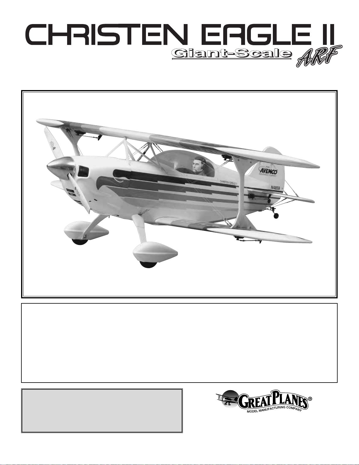
Congratulations and thank you for purchasing the Great
Planes Christen Eagle II ARF.Similar in size, shape, assembly
and flying characteristics to the Great Planes Pitts Special
ARF, the “Eagle” provides the same aerobatic thrills and
enjoyment as the Pitts. In fact, with the exception of a few
cosmetic details (such as the trim scheme, cowl, canopy,
wheel pants and the outline of the “tail feathers”), the Great
Planes Eagle has essentially the same airframe as the Pitts.
However, a few structural improvements have also been
incorporated into the Eagle, such as the scale location of the
flying wires, a shortened “engine box” to accommodate gas
engines, a two-place cockpit, two fuel tank mounting locations
and a servo tray for the throttle servo , receiv er and battery.The
full-size Christen Eagle II has a top wingspan of 19'11"
[6.07m]. The Great Planes ARF has a top wingspan of 68.5"
[.17m].Therefore, the scale of this model is 28.7%.There are
two versions of the original Christen Eagle;the Eagle I and the
Eagle II.The “II” preceded the “I” and seated two people. After
its introduction, the “Eagles” aerobatic team converted the
Eagle II to a single-seater Eagle I. Due to the popular ity of the
Eagle II, it was decided that this model would be a “II”as well.
For the latest technical updates or manual corrections to the
Great Planes Christen Eagle II ARF, visit the web site listed
below and select the Great Planes Christen Eagle ARF.If there
is new technical information or changes to this model, a “tech
notice” box will appear in the upper left corner of the page.
http://www.greatplanes.com/airplanes/index.html
The Great Planes Christen Eagle is an excellent sport-scale
model and is eligible to fly in IMAA events. The IMAA
(International Miniature Aircraft Association) is an
organization that promotes non-competitive flying of giantscale models. If you plan to attend an IMAA event, obtain a
copy of the IMAA Safety Code by contacting the IMAA at
the address or telephone number below, or by logging on to
their web site at:
IMAA
INTRODUCTION
TABLE OF CONTENTS
2
Page 3
www.fly-imaa.org/imaa/sanction.html
IMAA
205 S. Hilldale Road
Salina, KS 67401
(913) 823-5569
Though the Great Planes Christen Eagle II is an ARF and
may not hav e the same level of detail as an “all-out” scratchbuilt competition model, it is a scale model nonetheless and
is therefore eligible to compete in the Fun Scale class in
AMA competition. In Fun Scale, the “builder of the model”
rule does not apply. To receive the five points for scale
documentation, the only proof required that a full size
aircraft of this type in this paint/markings scheme did exist is
a single sheet such as a kit box cover from a plastic model,
a photo, or a profile painting, etc.If the photo is in black and
white other written documentation of color must be provided.
Contact the AMA for a rule book with full details.
If you would like photos of the full-size Eagle for scale
documentation, or if you would like to study the photos to
add more scale details, photo packs are available from:
Bob's Aircraft Documentation
3114 Y uk on Av e
Costa Mesa, CA 92626
Telephone: (714) 979-8058
Fax:(714) 979-7279
e-mail: www.bobsairdoc.com
1.Your Chr isten Eagle II should not be considered a toy, but
rather a sophisticated, working model that functions very
much like a full-size airplane. Because of its performance
capabilities, the Christen Eagle II, if not assembled and
operated correctly, could possibly cause injury to yourself or
spectators and damage to property.
2. You must assemble the model according to the
instructions. Do not alter or modify the model, as doing so
may result in an unsafe or unflyable model. In a few cases
the instructions may differ slightly from the photos.In those
instances the written instructions should be considered
as correct.
3.You must take time to build straight, true and strong.
4. You must use an R/C radio system that is in first-class
condition, and a correctly sized engine and components
(fuel tank, wheels, etc.) throughout the building process.
5.You must correctly install all R/C and other components so
that the model operates correctly on the ground and in the air .
6.You must check the operation of the model before every
flight to insure that all equipment is operating and that the
model has remained structurally sound. Be sure to check
clevises or other connectors often and replace them if they
show any signs of wear or fatigue.
7. If you are not already an experienced R/C pilot, you
should fly the model only with the help of a competent,
experienced R/C pilot.
8.While this kit has been flight tested to exceed normal use,
if the plane will be used for extremely high stress flying, such
as racing or if an engine larger than one in the
recommended range is used, the modeler is responsible for
taking steps to reinforce the high stress points.
9. WARNING: The cowl, wheel pants, landing gear fairings
and wing struts included in this kit are made of fiberglass,
the fibers of which may cause ey e , skin and respiratory tract
irritation.Never blow into a part (wheel pant, cowl) to remov e
fiberglass dust, as the dust will blow back into your eyes.
Always wear safety goggles, a particle mask and rubber
gloves when grinding, drilling and sanding fiberglass parts.
Vacuum the parts and the work area thoroughly after
working with fiberglass parts.
Remember:Take y our time and follow the instructions to
end up with a well-built model that is straight and true.
If you have not flown this type of model before, we
recommend that you get the assistance of an experienced
pilot in your R/C club for your first flights. If you're not a
member of a club, your local hobby shop has information
about clubs in your area whose membership includes
experienced pilots.
In addition to joining an R/C club, we strongly recommend y ou
join the AMA (Academy of Model Aeronautics). In addition to
other vital functions, the AMA, the governing body of model
aeronautics in the United States, provides insurance to
members who fly in compliance with the Safety Code. You
must be a member to fly at R/C clubs chartered by the
AMA–most of which are.The AMA can also direct you to the
closest club whose membership should have qualified flight
We, as the kit manuf acturer, provide you with a top quality ,
thoroughly tested kit and instructions, but ultimately the
quality and flyability of your finished model depends on
how you build it; therefore, we cannot in any way
guarantee the performance of your completed model, and
no representations are expressed or implied as to the
performance or safety of your completed model.
PRO TECT YOUR MODEL,YOURSELF
& OTHERS...FOLLOW THESE
IMPORTANT SAFETY PRECAUTIONS
Scale Competition
3
Page 4
instructors. To join the AMA, telephone, write or fax them at
the address below, or join on line at www.modelaircraft.org.
Academy of Model Aeronautics
5151 East Memorial Drive
Muncie, IN 47302-9252
Tele. (800) 435-9262
Fax (765) 741-0057
Or via the Internet at:
http://www.modelaircraft.org
This is a partial list of items required to finish the Great
Planes Christen Eagle II ARF that may require planning or
decision making before starting to build. Order numbers are
provided in parentheses.
Technically, the Christen Eagle is a giant-scale model, but
it's not really THAT large! Expensive, high-torque servos
aren't necessary to fly this model, but “standard” servos
should not be used either. Ser vos with a torque rating of at
least 50 oz-in [3.9 kg-cm] should be used on the ailerons,
elevator and rudder. If you plan on doing lots of aerobatic
flying where the rudder will be used heavily, you might
consider using an even higher torque servo for the rudder.
Of course, a standard servo may be used on the throttle.
Because the elevator servos move in opposition, either a
transmitter capable of electronic mixing must be used (so one
of the servos can be reversed); or use a separate, in-line
servo mixing device such as the Futaba®SR-10 Synchronized
Servo Reverser (FUTM4150) to reverse one of the servos.
A receiver battery pack with a capacity of no less than 1,000
mAh is also recommended.
The following servo extension cords and connectors were
also used to build this model:
❏ (2) Short Y-connectors such as the Futaba AEC-13 Dual
Servo Extension for Futaba radios for the ailerons in the
wings (FUTM4130).
❏ (1) 24" [610mm] Y-harness for connecting Y-connectors in
wings to the receiver (HCAM2500 for Futaba, HCAM2530
for JR®/Airtronics®Z/Hitec®).
❏ (7) 12" [300mm] servo extension for ailerons , rudder and
elevator servos (HCAM2100 for Futaba, HCAM2130 for
JR/Airtronics Z/Hitec).
Note: Instructions for mounting every possible engine
cannot be incorporated into this manual. Although there are
several engines suitable for powering the Christen Eagle
ARF, instructions are provided for mounting a Fuji™Engines
50SB spark-ignition engine, a U.S. Engines™41cc engine
and an O.S.®MAX 1.60 FX glow engine. Modelers using
different engines may refer to the instructions as a guide.
The recommended engine size range for the Eagle is
specified on the cover of this manual. All engines within the
specified range will power the Eagle well. At no time should
an engine larger than the recommended range be flown on
this model because it has not been tested for such use.
Powered by a two-stroke glow engine such as the O.S.MAX
1.60 FX, the Eagle is able to perform aerobatics and has been
said to fly quite “scale-like.”The Eagle also flies extremely well
with the O.S. MAX FT-300 four-stroke twin.With this engine,
the Eagle's vertical performance is virtually unlimited and it is
capable of hovering.Additionally, powered by the FT-300, the
Eagle has a pleasing, scale-like sound. Powered by the Fuji
BT-50 gas engine, the Eagle was very aerobatic and perfectly
able to handle the additional weight with no bad tendencies.
The Fuji BT-50 is an ideal gas power plant for the Eagle.It is
perfectly concealed within the cowl without having to cut
unsightly holes for the muffler, spark plug or engine head.
When making the decision between a gas engine and a
glow engine, while a gas engine may provide more power,
the additional weight of a gas engine can offset some of the
power advantage. However, the considerably lower cost of
gasoline compared to glow fuel should also be taken into
consideration when choosing a power plant for your Eagle.
If using the Fuji BT-50SB engine the Fuji Engines Short
Propeller Hub (FJIG6754) and (4) 1/4-20 x 1" [25mm] socket
head cap screws and lock washers for mounting the engine
will be required (1/4-20 blind nuts are included with the kit).
If mounting a different gas engine, different hardware may
be required.
If using the U.S. Engines 41cc, a 1/4" x 3-3/4" x 4-1/2" [6.4
x 100 x 115mm] sheet of aircraft plywood will be required for
making the engine mount plate.There is a template on page
50 of the manual
If using a two-stroke glow engine, a Bisson brand Pitts-style
muffler is recommended:
❏ BISG1180 for the Moki 2.10
❏ BISG4116 for the O.S.1.60 FX
❏ BISG4220 for the O.S.BGX 3500
❏ BISG2300 for the SuperTigre
®
3000 or 3250
Per the IMAA Safety Code, magneto spark-ignition engines
must have a coil-grounding switch on the aircraft to stop the
engine and prevent accidental starting. The switch must be
operated manually (without the use of the transmitter) and
accessible by the pilot and assistant. For use with the Fuji
Engine Recommendations
Radio Equipment
DECISIONS YOU MUST MAKE
4
Page 5
engine shown, the manually-operated switch was made
from a .3 Amp slide switch, 16-gauge wire and a covered,
crimp-on connector purchased at the local RadioShack.
Slightly different hardware may be required if using a
different spark-ignition engine. All of the components
required should also be available at any hardware or homeimprovement store.
The fuel tank, stopper and fuel line included with this kit is
suitable for use with glow fuel.However, if using a gasoline
engine, the stopper and line must be converted to work with
gas.There may be sever al different gas-compatib le stoppers
and lines available, but of the all the combinations tested,
the Du-Bro gas conversion stopper and Du-Bro medium
neoprene fuel tubing are the only ones recommended. The
Du-Bro stopper holds up best to gasoline and the Du-Bro
medium fuel tubing fits tightly and remains attached. Du-Bro
fuel line barbs are also highly recommended for keeping the
lines attached.To use the barbs however, the aluminum fuel
tubes that come with this tank must be replaced with brass
tubing so the barbs can be soldered on.
Following is a list of all the items required to convert the
stopper and fuel lines for use with gasoline:
❏ (1) Du-Bro #400 gas conversion stopper (DUBQ0675)
❏ (2) 2' [610mm] Du-Bro medium neoprene fuel tubing
(DUBQ0455)
❏ (2 pkgs.) Du-Bro #813 1/8" [3.2mm] I.D. fuel line barbs
(DUBQ0670)
❏ (1) 12" [300mm] piece of K+S 1/8" [3.2mm] soft brass
tubing (K+SR5128-box of 5)
Note: Modelers who use glow engines with large silicone
fuel tubing should also use fuel line barbs to ensure that the
larger tubing remains attached to the metal tubes in the
tank. If using fuel line barbs, the aluminum tubes supplied
with the fuel tank will have to be replaced with K&S brass
tubing so the barbs can be soldered on. Fuel line barbs are
not necessary when medium silicone fuel tubing is used.
The Christen Eagle ARF comes with all the hardware
necessary to add semi-scale flying wires. (The wires are
mounted near their scale locations, but the flying wires on
the full-size Eagle are rigid and streamlined rather than the
flexible cable used on this model). The flying wires are for
scale enhancement and are not necessary for flying, so the
Eagle may be flown with or without them. (Most pilots who
are more concerned with aerobatics than they are scale
appearance choose to fly without the wires due to the
additional set up time). To mount the flying wires, simply
follow the instructions in the manual.
While building the Christen Eagle ARF a building stand or
cradle is a necessity. We use the Robart Super Stand II
(ROBP1402) for all of our projects in R&D.
In addition to the items previously listed, following is a list of
the rest of the items required to finish the Christen Eagle II
ARF. Order numbers are provided in parentheses.
❏ Suitable propellers
❏ 1/4" [6mm] (HCAQ1000) or 1/2" [13mm] (HCAQ1050)
R/C foam rubber
❏ 3' [900mm] standard silicone fuel tubing (for glow
engine--GPMQ4131)
❏ 30% scale or 1/4-scale pilot
In addition to common household tools and hobby
supplies, following are the most important items required to
build the Eagle.
Great Planes Pro™CA and Epoxy glue
are recommended.
❏ 1 oz. [30g] Thin Pro CA (GPMR6002)
❏ 1 oz. [30g] Medium Pro CA+ (GPMR6008)
❏ CA applicator tips (HCAR3780)
❏ Pro 30-minute epoxy (GPMR6047)
❏ Epoxy mixing cups (GPMR8056)
❏ Microballoons (TOPR1090)
❏ Threadlocker thread locking cement (GPMR6060)
❏ RTV silicone cement or R/C-56 canopy glue (JOZR5007)
❏ Paint assortment and brushes for painting pilot
❏ Black or gray paint for cockpit and rear instrument panel
❏ Masking tape (TOPR8018)
❏ #1 Hobby knife (HCAR0105)
Adhesives and Building Supplies
Hardware and Accessories
ADDITIONAL ITEMS REQUIRED
Building Stand
Optional Flying Wires
Fuel T ank Setup
5
Page 6
Before starting to build, take an inventory of this kit to make sure it is complete, and inspect the parts to make sure they
are of acceptable quality. If any parts are missing or are not of acceptable quality, or if you need assistance with assembly ,
contact Product Support. When repor ting defective or missing parts, use the part names exactly as they are written in
the Kit Contents list.
3002 N. Apollo Drive, Suite 1
Champaign, IL 61822
Telephone: (217) 398-8970
Fax: (217) 398-7721
E-mail: airsupport@greatplanes.com
KIT INSPECTION
❏ #11 blades (100-pack, HCAR0311) -or- #11 blades (5-
pack, HCAR0211)
❏ Drill bits: 1/16" [1.6mm], 3/32" [2.4mm], 7/64" [2.8mm],
1/8" [3.2mm], an extended 3/16" [4.8mm] drill, or 3/16"
[4.8mm] brass tube sharpened on the end, 7/32"
[5.6mm], 19/64" [7.6mm] (if using gas engine)
❏ 8-32 tap and #29 drill (only if using glow engine--
GPMR8103)
❏ Small metal file
❏ 1/4" [6.4mm] wrench (for mounting wing struts)
❏ 3mm and 1.5mm hex wrench
❏ Prop Reamer (GPMQ5005)
❏ Stick-on segmented lead weights (GPMQ4485)
❏ Silver solder w/flux (GPMR8070)
❏ Soldering iron or torch for soldering
❏ K & S #801 Kevlar thread or similar (for stab alignment,
K+SR4575)
❏ Rotar y tool such as Dremel
®
❏ Rotar y tool reinforced cut-off wheel (GPMR8200)
❏ Rotary tool cutting bit (suitable for cutting small holes in
fiberglass cowl)
❏ Various small to medium-size C-clamps
❏ Sandpaper assor tment
❏ Small, metal straightedge
❏ Fine-point felt-tip pen such as a Top Flite® Panel Line
Pen (TOPQ2510)
❏ Denatured alcohol (for epoxy clean up)
❏ Naphtha lighter fuel or denatured alcohol (to remove
adhesive from masking tape)
❏ Dave Brown Carbon Fibre Tape (DAVR2000) for reinforcing
wheel pants (see page 24)
❏ 2 oz. [57g] spray CA activator (GPMR6035)
❏ CA debonder (GPMR6039)
❏ Epoxy brushes (6, GPMR8060)
❏ Mixing sticks (50, GPMR8055)
❏ Switch & Charge Jack Mounting Set (GPMM1000)
❏ Hobbico
®
Builder's Triangle Set (HCAR0480)
❏ Curved-tip canopy scissors for trimming plastic parts
(HCAR0667)
❏ Hobbico Duster
™
can of compressed air (HCAR5500)
❏ Milled fiberglass (GPMR6165)
❏ Hobby Heat
™
micro torch (HCAR0750)
❏ Dead Center
™
Engine Mount Hole Locator (GPMR8130)
❏ AccuPoint
™
Laser incidence meter (GPMR4020)
❏ Precision Magnetic Prop Balancer™ (TOPQ5700)
❏ 21st Centur y
®
sealing iron (COVR2700)
❏ 21st Centur y iron cover (COVR2702)
-or-
❏ Top Flite
®
MonoKote®sealing iron (TOPR2100)
❏ Top Flite Hot Sock
™
iron cover (TOPR2175)
• The Christen Eagle II ARF is factory-covered with Top
Flite MonoKote film. Following are the colors used and
order numbers for 6' [1.8m] rolls.
White TOPQ0204
Yellow TOPQ0203
Orange TOPQ0202
True red TOPQ0227
Sapphire Blue TOPQ0226
• The stabilizer and wing incidences and engine thrust
angles have been factory-built into this model. However,
some technically-minded modelers may wish to check
these measurements anyway. To view this information,
visit the web site at www.greatplanes.com and click on
“Technical Data.” Due to manufacturing tolerances
which will have little or no effect on the way your model
will fly, please expect slight deviations between your
model and the published values.
IMPORTANT BUILDING NOTES
Covering T ools
Optional Supplies and Tools
Page 7
7
1 Fuselage w/balsa LG cover (two 1/4-20 blind
nuts and five 4-40 blind nuts f actory installed)
2 Fiberglass cowl
3 R&L top wing panels w/ailerons
4 R&L bottom wing panels w/ailerons
5 Stab & elevators
6 Fin & rudder
7 Canopy
8 Top, center wing panel
9 R&L fiberglass wing struts
10 R&L aluminum cabanes
11 Rear instr ument panel
12 4" [100mm] polished aluminum spinner
(cone, backplate, spacers (2), bolt)
13 R&L adjustable engine mount
14 Battery mount
15 Lower fuel tank mount (optional)
16 Servo tray
17 Cowl ring
18 (3) forward bottom wing joiners
19 (3) aft bottom wing joiners
20 Servo tray brace
21 (2) aft top wing joiners
22 (2) forward top wing joiners
23 (8) guide tube supports
24 Fuel tank w/hardware
25 R&L fiberglass wheel pants
26 Aluminum landing gear
27 (2) 4" [100mm] main wheels
28 (2) fiberglass landing gear fairings
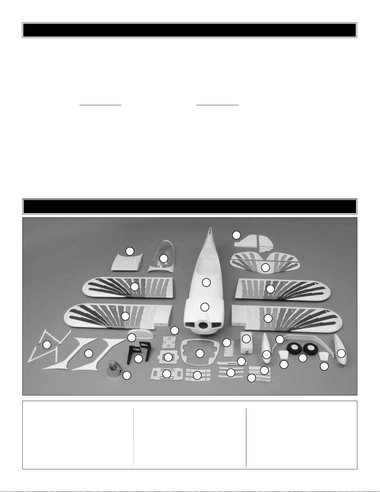
Kit Contents (Photographed)
To order replacement parts for the Great Planes Christen Eagle II ARF, use the order numbers in the Replacement P arts
List that follows.Replacement par ts are available only as listed. Not all par ts are available separately (an aileron cannot
be purchased separately, but is only available with the wing kit). Replacement parts are not available from Product
Support, but can be purchased from hobby shops or mail order/Internet order firms. Hardware items (screws, nuts, bolts)
are also available from these outlets. If you need assistance locating a dealer to purchase parts, visit
www.greatplanes.com and click on “Where to Buy.” If this kit is missing parts, contact Product Suppor t.
Replacement Parts List
Missing pieces:.......Contact Product Support
Instruction manual:.......Contact Product Support
Full-size plans: .......Not available
ORDERING REPLACEMENT PARTS
Order Number
GPMA2440...................T op Wing Set
GPMA2441 ............Bottom Wing Set
GPMA2442..........................Fuselage
GPMA2443 ..............Tail Surface Set
GPMA2444..........Cowl w/Cowl Ring
GPMA2445............................Canopy
GPMA2446 ....................Wheel Pants
GPMA2447..................Landing Gear
Order Number
GPMA2448.........................Decal Set
GPMA2449..........................Cabanes
GPMA2450...........Metal Bracket Set
GPMA2451.....................Wing Struts
GPMA2452 ................LG Fairing Set
GPMA2453............................Spinner
GPMA2454 ...............Flying Wire Set
GPMQ4245........Tail Gear Assembly
KIT CONTENTS
4
10
9
12
8
7
3
14
11
13
15
16
1
2
17
18
23
19
6
5
3
4
24
20
21
22
25
26
27
28
25
28
Page 8
8
WASHERS:
(5) #4 lock washers (cowl ring)
(13) #4 flat washers (5-cowl ring, 8-wing strut
mounting)
(14) #8 flat washers (6-main wheel spacers, 8
glow engine mounting)
(8) #8 lock washers (4-GP engine mount to
firewall, 4-engine to GP mount)
FL YING WIRE CABLES:
(Measurements are from clevis pin to clevis pin)
(2) "Y" bottom tail wires
(4) 10-1/4" [260mm] top tail wires
(4) 21-1/2" [545mm] top wing to fuselage
(4) 22-1/4" [565mm] top wing to bottom wing
(1) bottom tail wire bracket
(30) clevis retainers
SHEET-METAL SCREWS:
(50) #4 x 1/2" [13mm] screw (16-aileron control
horns, 4-wheel pant mounting, 30-various
strut, cabane & bracket mounting)
(2) #4 x 5/8" [16mm] screw (tail gear mounting)
(6) #8 x 5/8" [16mm] screw (main LG mounting)
(8) #2 x 3/8" [10mm] button-head screw (canopy)
WHEEL COLLARS:
(4) 3/16" [4.8mm] wheel collars (main wheels)
(2) 3/32" [2.4mm] wheel collars (on rudder
pushrod for tail steering)
(3) 3mm wheel collars
(4) 3mm set screws for tail gear wire
NYLON:
(2) 2" x 9" [50 x 230mm] CA hinge strip
(7) large control horns (4-ailerons, 2-elevators,
1-rudder)
(3) mounting plate for large control horns (2-
elevator, 1-rudder)
(2) 1/4-20 x 2" [50mm] nylon wing bolts
(1) 4-40 torque rod horn (tail steering)
(2) ball link (tail steering pushod, throttle)
(1) clevis (throttle)
(1) nylon retainer for screw lock
TAIL GEAR PARTS:
Aluminum tail gear mount
Tail gear wire
1-1/4" [32mm] tail wheel
Steering arm
(3) 3mm wheel collars
(4) 3mm set screws
(2) springs (not used)
(2) 3 x 12mm screws
PLYWOOD PARTS:
(4 sets) cowl ring mounting tabs
(2) wheel pant braces
(2) brace doublers
(4) axle braces
METAL HARDWARE:
(7) 4-40 threaded metal clevis (4-ailerons, 2-
elevators, 1-rudder)
(7) Large solder clevis (4-ailerons, 2-elevators,
1-rudder)
(1) small solder clevis (tail steering pushrod)
(2) 3/16" x 2" [4.8 x 50mm] axles
(30) small threaded metal clevis
MACHINE-THREAD SCREWS:
(4) 8-32 x 1-1/4" [32mm] SHCS (GP engine
mount to firewall)
(4) 8-32 x 1" [25mm] SHCS (engine to GP mount)
(1) 8-32 x 3/4" [19mm] SHCS (drawing blind
nuts into firewall)
(15) 4-40 x 1/2" [13mm] SHCS (5-cowl ring, 10-
wing strut & cabane mounting)
(12) 4-40 x 3/4" [19mm] SHCS (rudder & elevator
control horns)
(2) 4-40 set screws (for wheel collars for tail
steering)
(1) 2-56 ball link ball (tail steering arm)
(4) 6-32 x 1/4" [6mm] SHCS (main landing gear
wheel collars)
(1) 4-40 x 1/8" [3mm] SHCS (for screw-lock)
(1) 2-56 ball link ball (carb end of throttle)
(6) 4-40 x 5/8" [16mm] screw (tail wire bracket
mounting)
PUSHRODS:
(4) 4-40 x 4-1/2" [115mm] pushrod (ailerons)
(3) 4-40 x 5-3/4" [145mm] pushrod (elevators-2,
rudder-1)
(1) 2-56 x 12" [305mm] pushrod (tail steering)
(1) 24" [610mm] pushrod tube (throttle)
(1) 24" [610mm] white, plastic pushrod (throttle-
gas)
(1) 2-56 x 36" [910mm] throttle pushrod (glow)
(2) 2-56 x 1" [25mm] threaded rod (throttle gas)
SOLID WOOD PARTS:
(2) 3/8" x 1-3/16" [10x 30mm] wing dowels
(2) 1/8" x 10" [3 x 250mm] wood dowels (firewall)
NUTS:
(9) 4-40 blind nuts (5 factory-installed for cowl ring,
4 extras for relocating screws if necessary)
(6) 1/4-20 blind nuts (2 factory-installed for wing
bolts, 4 mounting gas engines)
(13) 4-40 nut (7-clevis jam-nuts, 6-tail wire
bracket mounting)
(31) 2-56 nut (tail steering ball link ball)
(4) 8-32 blind nuts (for GP engine mount)
(2) large axle nuts (landing gear axles)
(2) 2-56 nuts (for ball link ball on carb and on
tail wheel steering arm)
(10) 4-40 lock nuts (wing strut & cabane
mounting)
OTHER:
(18) silicone retainers (pushrod clevises)
(4) #64 Rubber bands (fuel tank mounting)
(6) 3/8" [10mm] heat shrink tubing (for servo
extensions)
(1) 1" x 12" [25 x 300mm] fiberglass tape (cowl
ring)
(1) brass body screw-lock connector (servo end)
(1) 4" [100mm] brass tube (for tail wire collars)
(2) Velcro strips
Decal set
Extended 3/32" [2.4mm] ball-end hex wrench
(1) 3" Silicone tubing (for tail steering pushrod)
Kit Contents (Not Photographed)
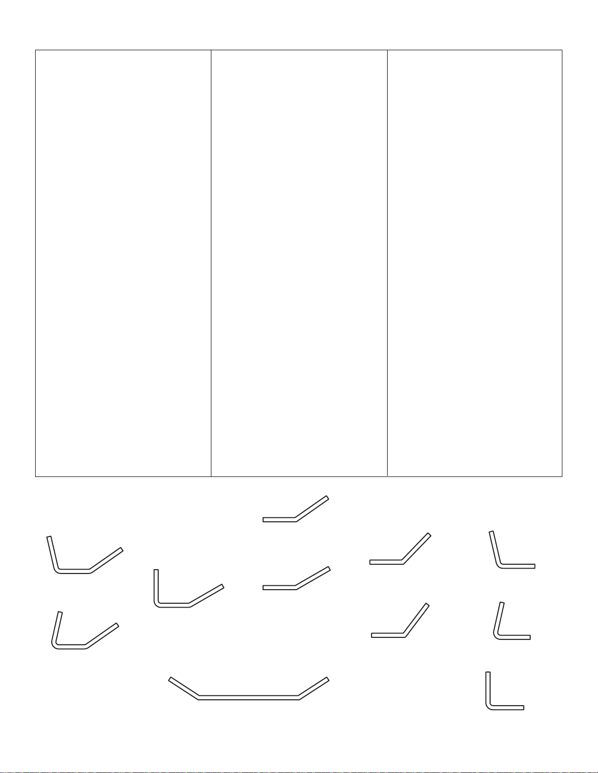
METAL BRACKETS:
There are a total of thirty-five metal brackets used
to mount the wings and optional flying wires.Below
is a description and sketch of each bracket.
(2) bottom, front wing struts
(2) top, front wing struts
(12) stab flying wire mounts,
wing flying wire mounts
(2) top, center of wing flying
wire mounts
(4) fin flying wire mounts
(2) bottom, aft wing struts
(2) top, aft wing struts
(2) top, forward cabane mounts
(1) Bottom of fuselage for tail
(2) top, aft cabane mounts
(4) fuselage flying wire
mounts near LG
A1
A2
A3
Bottom T ail Bracket
B1
B2
B3
B4
C1
C2
C3
Page 9
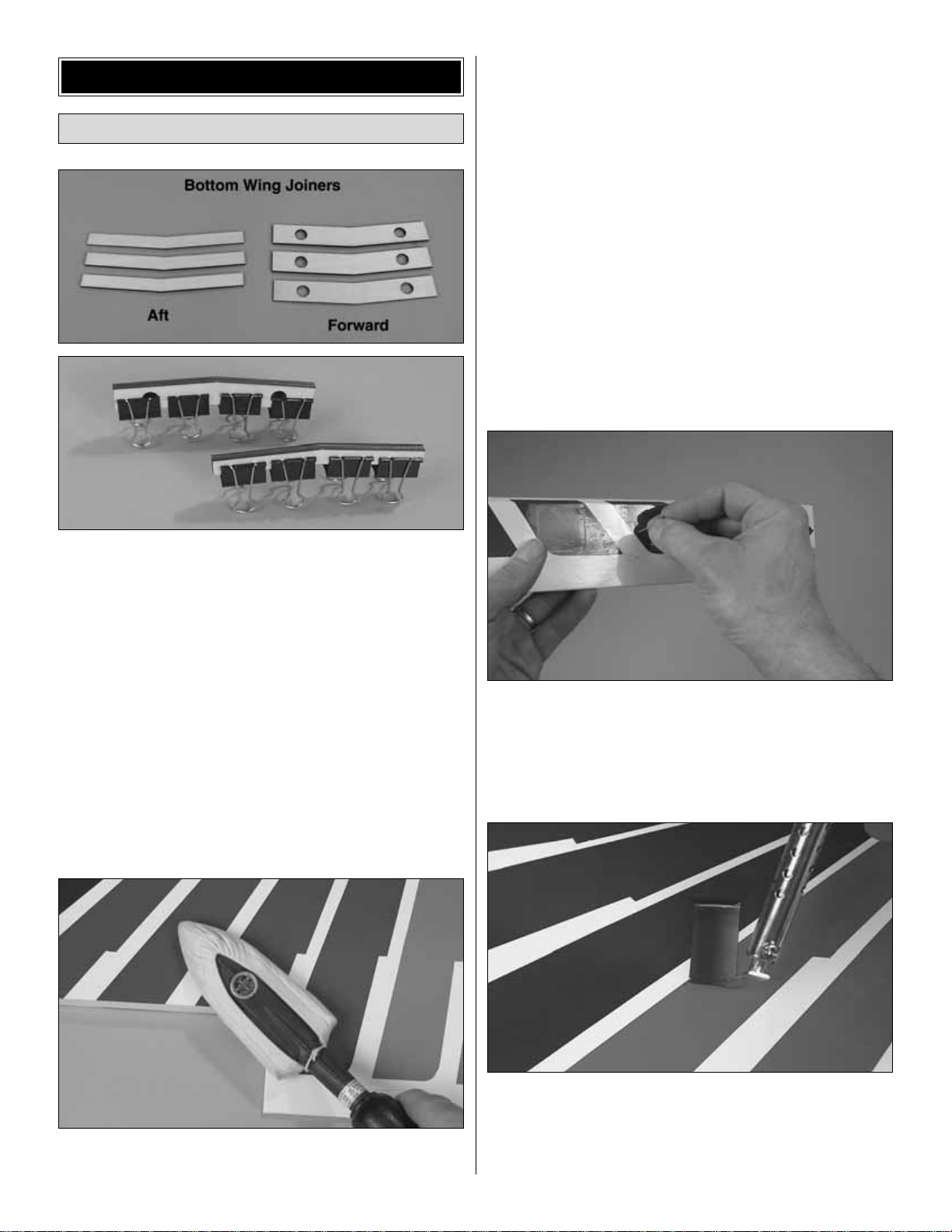
❏ 1. Use 30-minute epoxy to glue together the three
plywood aft bottom wing joiners and the three plywood
forward bottom wing joiners. Clamp the joiners together
and wipe away excess epoxy. (Steel spring clamps are ideal
for holding the joiners together.) Note: If you happen to
notice that one of the joiners is thinner than the other two, it
doesn’t matter where in the “stack” it is positioned.
Now the joiners will be ready when it’s time to glue together
the bottom wings.
Start with the bottom, left wing panel first so yours
looks like the photos the first time through.
❏ 2. Carefully remove the masking tape holding the aileron
to the wing. Residual adhesive from the tape may be
removed with naphtha lighter fuel or denatured alcohol.
❏ 3. Use a covering iron with a covering sock to thoroughly
bond the covering to the structure and remove any wrinkles in
the wing and aileron.The best way is to glide the iron over the
covering until the wrinkles disappear, then push down on the
iron to bond the covering to the wood. If you come across a
wrinkle that won’t go away, the balsa in that area may be
bending inward. If this is happening, do not apply pressure.
Simply let the heat of the iron shrink the covering. If the
wrinkles momentarily disappear, then immediately reappear,
the iron may be too hot, thus causing air bubbles. Lower the
temperature of the iron or use a sharp #11 blade to puncture
several small holes in the covering, then reheat. The
suggested iron temperature is around 360 degrees F. Hint:
Any MonoKote pigment that gets smeared on other areas
may be removed with a tissue lightly dampened with
MonoKote Trim Solvent or CA debonder. Trim solvent and
debonder are powerful, so using too much may loosen the
covering if it gets under the seams.To avoid this, immediately
wipe away excess solvent using another tissue dampened
with household spray cleaner (Windex®, Formula 409®).
Suggestion: Before tightening the covering over the ailerons,
use a pin to poke six to eight holes in the covering over each
lightening hole on the bottom.(Where possible, poke the holes
in colored areas where there are two layers of co vering.) When
heating the covering, expanding air will escape through the
holes, thus allowing the covering to fully tighten.
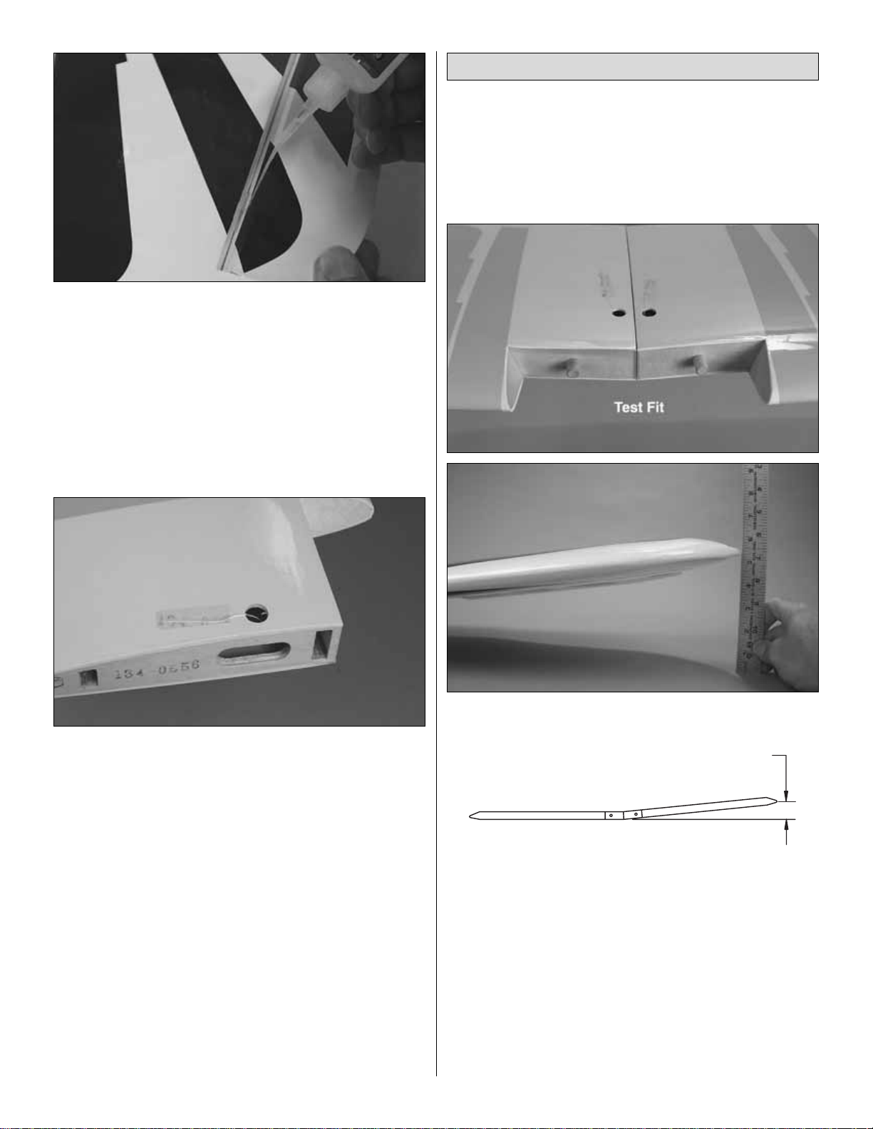
❏ 4. While you’ve got your covering tools out, use a
straightedge and a hobby knife to cut the covering 1/8"
[3mm] inside the edges of the opening in the bottom of the
wing panel for the aileron servo.Use a trim seal tool to iron
the covering down inside the edges of the opening.
Prepare the Wings
ASSEMBLE THE WINGS
9
Page 10
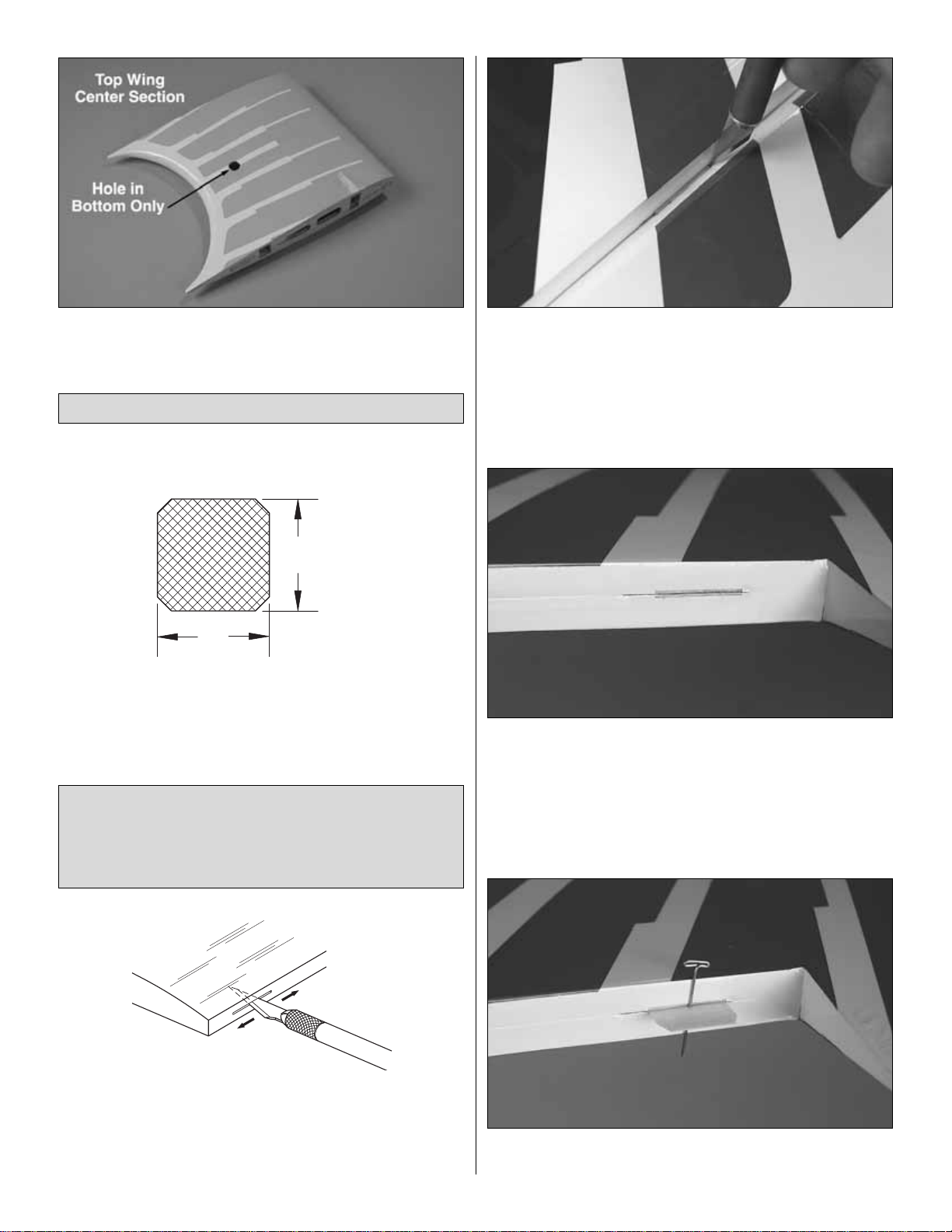
❏ 5. Cut the covering from the hole in the bottom of the
center section for the aileron servo wire.
Again, start with the bottom, left wing first…
❏ 1. Only three hinges are required for each aileron, but you
might as well go ahead and cut all the hinges now .Cut twentytwo 1" x 1" [25 x 25mm] CA hinges from the supplied CA
hinge strips. Cut off the corners so the hinges go in easier.
❏ 2. Test fit the aileron to the wing with the hinges. If the
hinge slots are too tight, enlarge the slots using a hobby
knife with a #11 blade. Move the blade from side-to-side to
loosen the slots.Note that it’s the back side of the blade that
does the work.
❏ 3. In order for the CA to get full penetration all the way into
the hinge slots a strip of covering must be removed from each
slot. This is done by first marking the ends of the hinge slots
with small slits cut in the covering in the wing and aileron.
❏ 4. Remove the aileron and take out the hinges. Use a
small metal ruler and a #11 blade to cut a small strip of
covering from the hinge slots between the slits.
❏ 5. Inser t a T-pin through the middle of three hinges. Install
the hinges in the wing, then join the aileron.Remove the T-pins.
Note: The following three steps describe how to prepare
the hinge slots for gluing in the CA hinges.This procedure
may appear to be a little more “involved” than one would
prefer for an ARF, but you will be rewarded with close, clean
hinge gaps and free-moving, securely hinged surfaces.
Hinge the Ailerons
10
1" [25mm]
1"
[25mm]
Page 11
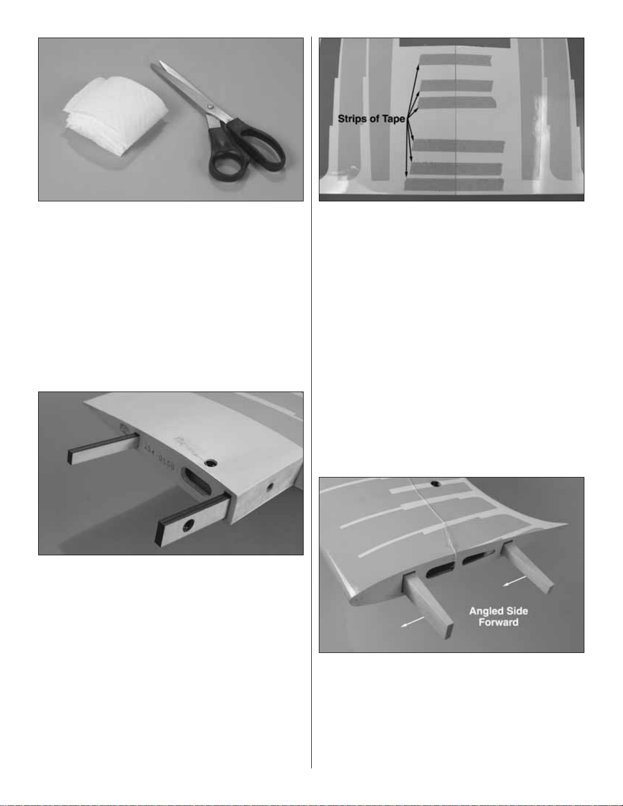
❏ 6. Adjust the aileron so there is a small gap between the
trailing edge of the wing and the leading edge of the
aileron—just enough to see light through or to slip a piece of
paper through. Add six to eight drops of thin CA to both
sides of all three hinges. Using a CA applicator tip is highly
recommended. Allow enough time between drops to allow
the CA to soak in—otherwise, excess CA will get into the
hinge gap.
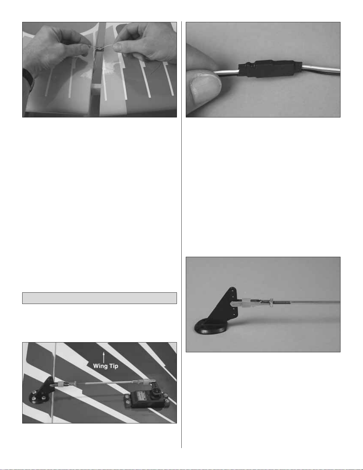
❏ 7. Tighten the covering, open the servo hatches and join
the ailerons to the remaining three wing panels the same way.
❏ 8. Cut the covering from the openings in the bottom wing
panels for the servo wires and the wing bolts.Tape the string
for the servo wires to the top of the panels.
Do the bottom wing first…
❏ 1. Round both ends of the 3/8" x 1-3/16" [10 x 30mm]
hardwood wing dowels.
❏ 2. Use a bar sander with coarse sandpaper to tr ue the
edges and remove any excess hardened epoxy from the
forward and aft bottom wing joiners prepared earlier.
Without using any glue, test join the bottom wings with the
joiners and the dowels.Make any adjustments necessary for
a good fit. The dihedral angle of the bottom wing is factoryset and determined by the angle of the wing joiners.
However, those who wish to confirm the dihedral angle may
do so by placing one wing panel flat on the workbench and
measuring the distance from the tip of the other panel to the
bench. The distance should be 5-1/4" [133mm], but small
variances are acceptable.
Join the Wings
11
BOTT OM WING
5-1/4"
[133mm]
Page 12
❏ 3.Lay two or three paper towels on top of each other .Use
scissors to cut them into smaller squares. These will come
in handy throughout assembly. Gather the rest of the items
required for joining the bottom wing including 30-minute
epoxy, a mixing cup, an epoxy brush, mixing sticks, masking
tape and a sheet of wax paper to protect your workbench.
The key to a secure wing joint is applying epoxy to all
contacting surfaces—this means both inside the wing
between the spars and to the joiners…
❏ 4. Mix approximately 1 oz. [30ml] of 30-minute epoxy.
Working quickly, pour a generous amount into one wing
half where the joiners go. Use a piece of wire or a dowel to
thoroughly spread the epoxy, coating all surfaces inside.
Coat the end of the wing and one half of both joiners with
epoxy. Inser t the coated ends of the joiners into the wing.
Immediately proceed to the next step.
❏ 5. Coat the inside and the end of the other panel with
epoxy. Also coat the protruding end of the joiners in the first
panel. Join the wings and wipe away excess epoxy as it
squeezes out. Coat one end of the dowels with epoxy, then
insert them into the wings.Be certain the dowels ke y into the
holes in the forward joiner. 3/8" [10mm] of the dowels should
protrude. Immediately proceed to the next step.
❏ 6. Tightly tape the wing together with several strips of
masking tape on the top and bottom. Use the small paper
towel squares dampened with denatured alcohol to wipe
away excess epoxy as the tape is applied. Be certain the
trailing edges of both wing halves accurately align.After the
wing is all taped together, epoxy under any of the strips of
masking tape can be wiped away by removing the strip,
wiping away the epoxy, then replacing the strip.After all the
epoxy has been cleaned up, set the wing aside and do not
disturb until the epoxy has hardened.
❏ 7. After the epoxy joining the bottom wings has
hardened, remove the masking tape.If there is still residual
hardened epoxy that you weren’t able to remove before, you
may be able to pic k it off with a #11 b lade or, in some cases,
remove it with a paper towel square wetted with denatured
alcohol. Use a covering iron with a covering sock to re-bond
any covering that lifted while peeling off the masking tape.
Now join the top wing. One outer panel at a time will be
joined to the center panel…
❏ 8. Without using any glue, test fit the outer panels to the
center panel with the forward and aft top wing joiners.The
angled side of the joiners faces forw ard.There is no dihedral
in the top wing, so it should be flat. Make any adjustments
necessary for a good fit.
❏ 9. Untape the strings on the ends of both outer panels
and on both ends of the center panel. Temporarily put the
strings inside the wings so they will not be in the way.
12
Page 13
❏ 10. Prepare 1 oz. of 30-minute epoxy .The same as when
joining the bottom wing, thoroughly coat one side of the
joiners and all mating surfaces of one side of the center
panel and the adjoining outer panel with epoxy. Take the
strings back out of the ends of the joining panels. Slide the
panels together until they are about 3/4" [19mm] apart. Tie
the ends of the strings together. Slide the panels the rest of
the way together, simultaneously pulling the str ing from the
aileron servo opening. Tightly tape the panels together,
wiping away excess epoxy as it squeezes out.
❏ 11. Pulling the string from both ends (from the servo
opening in the outer panel and from the other end of the
center panel), shift the string back and forth a few times to
make sure it does not get glued inside the wing. Do this a
few times as the epoxy continues to harden. Set the wing
aside until the epoxy fully hardens.
❏ 12. Remove the masking tape and join the other outer
panel to the other side of the center panel. Be sure not to
glue the string in the wing. After the epoxy hardens remove
the masking tape and tighten the covering.
Start with the bottom, right wing so yours looks like the
photos the first time through…
Refer to this photo while mounting the aileron servo.
❏ 1. Test fit the aileron servo in the servo opening in the
bottom of the wing. If necessary, use a hobby knife to
enlarge the opening to fit the servo.
❏ 2. Connect a 12" [300mm] servo extension wire to the
aileron servo. Slip a 1-1/2" [38mm] piece of heat shrink
tubing supplied with this kit over the connection, then
carefully shrink the tubing with a small flame (from a
soldering torch) or a heat gun. Tie the string in the servo
opening to the end of the servo wire. Pull the wire through
the wing and out of the hole in the middle. Place the servo
in the opening.
❏ 3. Drill 1/16" [1.6mm] holes into the wing for mounting the
servo.Mount the ser vo using the screws that came with it.
❏ 4. IMPORTANT! Remove the screws and the servo.Add
a few drops of thin CA to the holes to harden the “threads.”
Allow the CA to fully harden, then remount the servo.
❏ 5. Make a one-ar m servo arm by cutting off the unused
arms. Install the arm on the ser vo.
❏ 6. Thread a 4-40 nut and a 4-40 clevis onto a 4-40 x 4-
1/2" [115mm] pushrod. Slip a silicone retainer over the
clevis. Connect the clevis to the middle hole of a nylon
control horn.
❏ 7. Position the control horn on the aileron with the
pushrod in alignment with the servo arm. Make sure the
horn is on the hardwood plate built into the aileron.Push the
control horn into the aileron until the spikes on the bottom
lock into the wood.Using care not to drill all the way through
the aileron, drill four 3/32" [2.4mm] holes for mounting the
horn.Mount the control horn to the aileron with four #4 x 1/2"
[13mm] screws.
Hook Up the Ailerons
13
Page 14
❏ 8. IMPORTANT! The same as was done with the servo
mounting screws, remove the screws holding the control
horn to the aileron and add a few drops of thin CA to harden
the “threads” in the aileron. Allow the CA to fully harden,
then remount the horn.
❏ 9. Center the aileron and servo arm. Cut the pushrod to
the correct length, then solder it to a large, non-threaded
metal clevis using the techniques described in the following
Expert Tip.
How to Solder
❏ 1. Use denatured alcohol or other solvent to thoroughly
clean the pushrod. Use coarse sandpaper to roughen the
end of the pushrod where it is to be soldered.
❏ 2. Apply a few drops of soldering flux to the end of the
pushrod, then use a soldering iron or a torch to heat it. “Tin”
the heated area with silver solder (GPMR8070) by applying
the solder to the end. The heat of the pushrod should melt
the solder—not the flame of the torch or soldering iron—
thus allowing the solder to flow. The end of the wire should
be coated with solder all the way around.
❏ 3.Place the clevis on the end of the pushrod.Add another
drop of flux, then simultaneously heat the clevis and pushrod.
Slide the clevis the rest of the way onto the pushrod as the
solder melts. Apply another small amount of solder while the
pushrod and clevis are still hot.The same as before, the heat
of the parts being soldered should melt the solder, thus
allowing it to flow. Allow the joint to cool naturally without
disturbing. Avoid excess blobs, but make certain the joint is
thoroughly soldered.The solder should be shiny, not rough.If
necessary, reheat the joint and allow to cool.
❏ 4. Immediately after the solder has solidified, but while it
is still hot, carefully use a cloth to quickly wipe off the flux
before it hardens.Important: After the joint cools, coat with
oil to prevent rust.Note: Do not use the acid flux that comes
with silver solder for electrical soldering.
This is what a properly soldered clevis looks like; shiny
solder with good flow, no blobs, flux removed.
❏ 10. Slide a silicone retainer over the clevis, then connect
the aileron to the servo with the pushrod. The clevis will be
adjusted and the nut will be tightened when setting up the
radio later.
❏ 11. Mount and hook up the remaining three aileron
servos the same way. Note: The servo arms on all four
servos should “point” toward the wing tips.
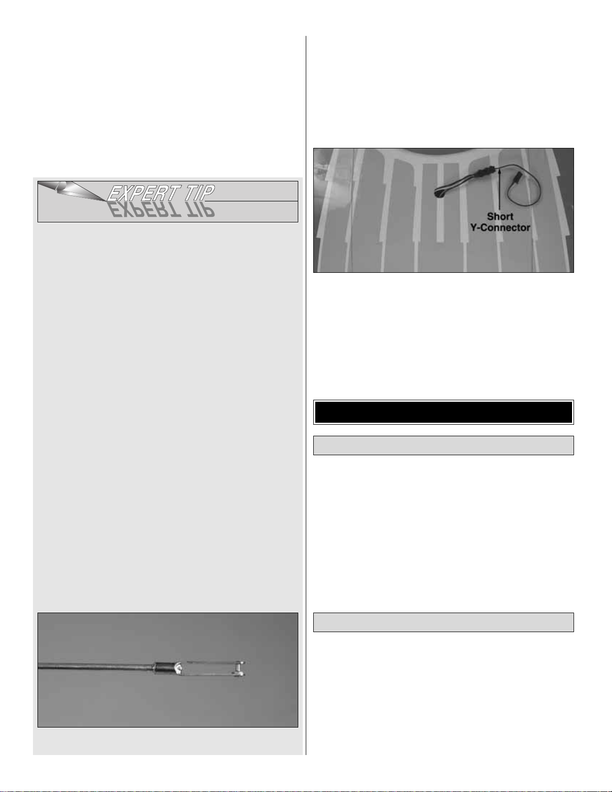
❏ 12. Connect the aileron servo wires in the wings to a
short Y-connector such as the Futaba AEC-13 J-series dual
extension cord (FUTM4130 for Futaba). Secure the
connection with tape or heat shrink tubing.
Hey, that’s about it for the wings. Set the wings in a safe
place (but not too far away!) and get ready to start on
the fuselage.
❏ 1. Remove the masking tape and separate the elevators
from the stab and the rudder from the fin.The same as was
done with the ailerons, use a pin to poke sev er al holes in the
covering on the bottom of the stab and elevators and in one
side of the fin and rudder to allow air to escape while
tightening the covering. Use a covering iron with a covering
sock to tighten the covering.
❏ 2. Prepare all the hinge slots by test fitting the hinges and
cutting a strip of covering from each slot.
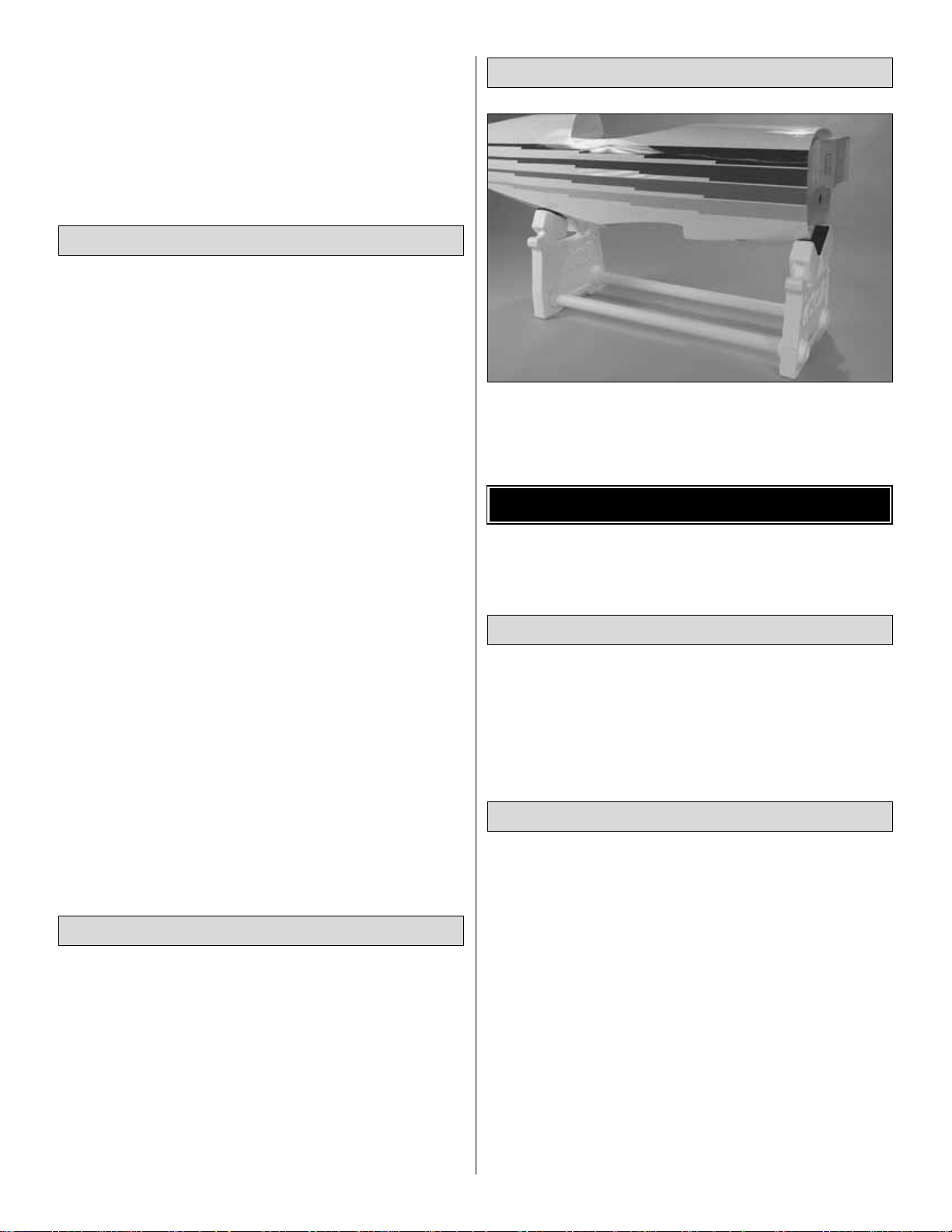
If you haven’t yet done so, get a building stand to
support the fuselage while working on it.The Robart
Super Stand II (ROBP1402) is recommended.
❏ 1. Peel off the masking tape and remove the balsa
landing gear cover from the bottom of the fuselage. The
same as was done with the wings and tail surfaces, use a
covering iron with a covering sock to tighten the covering
and remove any wrinkles from the fuselage.
Join the Stab and Fin to the Fuselage
Prepare the Tail Surfaces for Hinging
ASSEMBLE THE FUSELAGE
14
Page 15
❏ 2. Cut the covering from the slots in both sides of the
fuselage for the stabilizer and cut the covering 1/8" [3mm]
inside the edges of the openings for the two elevator and
one rudder servos.Seal the covering inside the edges of the
servo openings.
❏ 3.Tempor arily place the rudder and elevator servos in the
servo openings (for now, it doesn’t matter which way the
servos go—this step is just for drilling the holes before the
stab is glued in). Drill 1/16" [1.6mm] holes for the servo
mounting screws. Install, then remove the screws and
servos. Add a few drops of thin CA to the screw holes.The
servos will be mounted after the stab has been glued in.
❏ 4. Bolt the bottom wing to the fuselage with two 1/4-20 x
2" [50mm] nylon bolts. Slide the stab into the fuselage and
temporarily center it as best as you can by eye. Stand
approximately ten feet behind the model and view the
alignment of the stab and wing. If the stab is not parallel with
the wing, place a small weight on the “high side”of the stab to
bring it into alignment. If weight is not enough, remove the
stab from the fuselage and lightly trim or sand the stab saddle
as necessary until you can get the stab parallel with the wing.
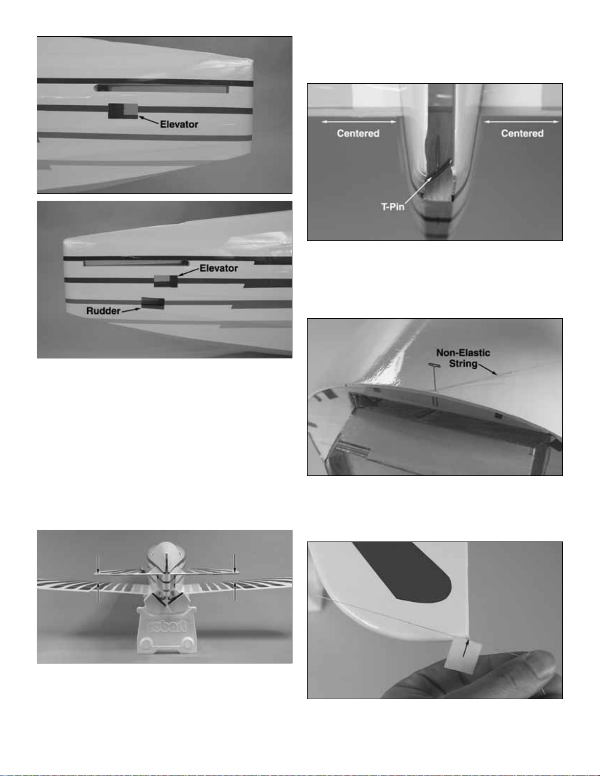
❏ 5. Once the stab and wing align, center the trailing edge
of the stab from side-to-side in the fuselage, taking accurate
measurements. Stick a T-pin through the back of the
fuselage into the stab.This will allow the front of the stab to
be shifted while keeping the trailing edge centered.
❏ 6. Stick a T-pin through the top of the fuselage over the
center stringer at F-1.Tie a loop in one end of a 50" [1270mm]
piece of non-elastic string such as monofilament or Kevlar line
(K+SR4575). Slip the loop in the string over the T-pin.
❏ 7. Fold a piece of masking tape over the string near the
other end and draw an arrow on it. Slide the tape along the
string and align the arrow with one end of the stab as shown
15
Page 16
in the photo. Swing the string over to the same position on
the other end of the stab. Pivot the stab on the T-pin in the
trailing edge and slide the tape along the string until the
arrow aligns with both ends of the stab.
❏ 8. Use a fine-point felt-tip pen such as a Top Flite
®
Panel
Line Pen (TOPQ2510) to mark the outline of the fuselage all
the way around both sides of the stab.
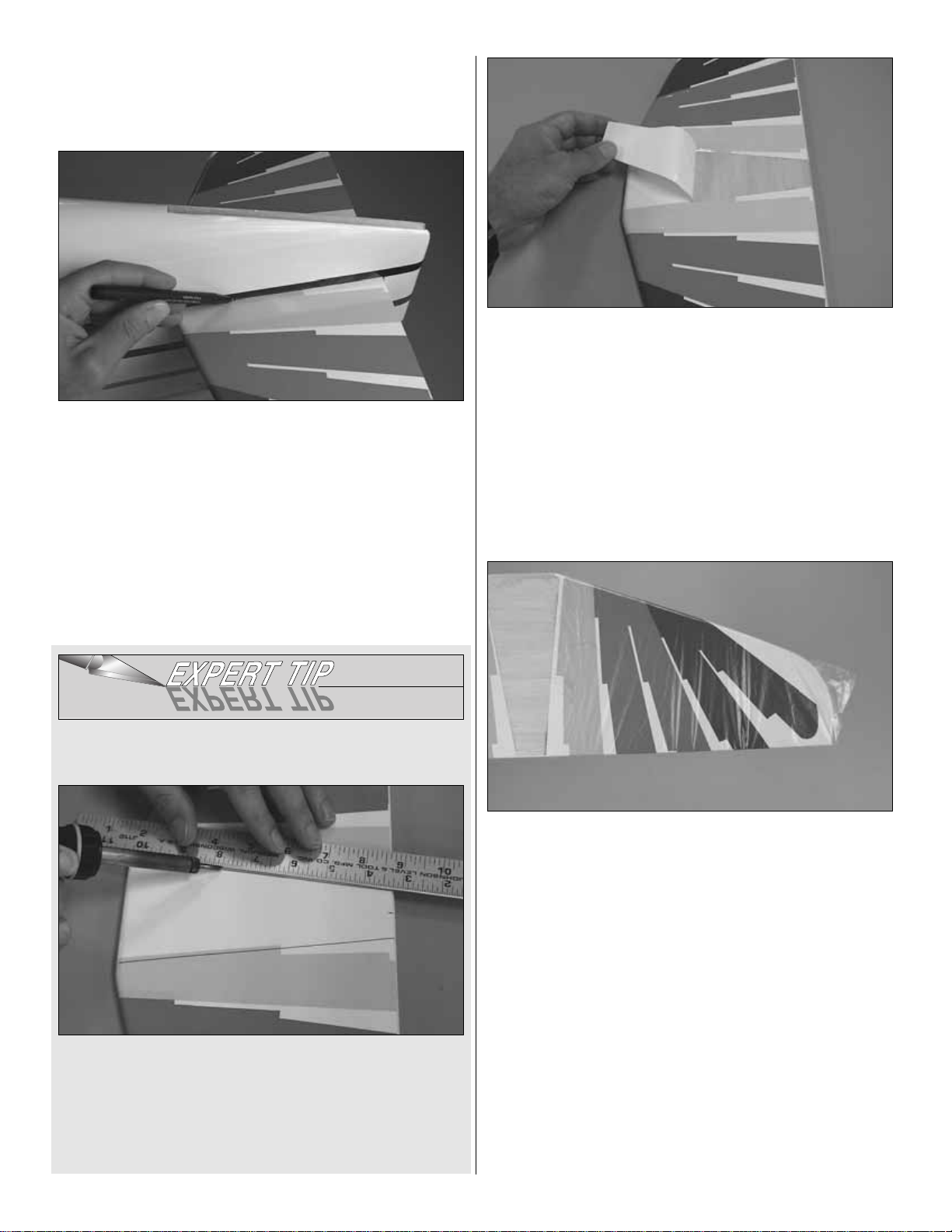
❏ 9. Remove the stab from the fuselage.Use a single-edge
razor blade, a sharp,new #11 blade or follow the Expert Tip
below to cut the covering from the stab along the lines.Use
care to cut only into the covering and not into the wood.
Cutting into the balsa will weaken the structure.
How to Cut Covering from Balsa
To avoid cutting into the balsa, use a soldering iron instead
of a hobby knife to cut the covering.The tip of the soldering
iron doesn’t have to be sharp, but a fine tip does work best.
Allow the iron to heat fully. Use a straightedge to guide the
soldering iron at a rate that will just melt the covering and not
burn into the wood. The hotter the soldering iron, the faster
it must travel to melt a fine cut.
❏ 10.Peel the covering from the center of the stab .Remove
any ink with one of your paper towel squares dampened with
denatured alcohol. Re-seal the ends of the covering to the
stab where it may have lifted while peeling off the covering
in the middle.
❏ 11. Wrap one side of the stab with a thin plastic bag or
cellophane to protect it from epoxy when it’s time to glue it
into position.
❏ 12.Thoroughly coat the top and bottom of the stab saddle
area in the fuselage where the stab fits and the top and bottom
of the stab with 30-minute epoxy. Slide the stab into position.
Remove the plastic wrap and use y our paper to w el squares to
wipe off excess epoxy.Check the stab alignment the same way
you did before by viewing the alignment with the wing,
centering the trailing edge and using the pin and string. Do not
disturb the fuselage until the epoxy has hardened.
16
Page 17

❏ 13. After the epoxy on the stab has hardened, slide the
fin into position. Holding the rudder to the fin, make cer tain
the top of the rudder aligns with the top of the fin and the
bottom of the rudder aligns with the bottom of the fuselage.
Also make sure the trailing edge of the fin is parallel with the
end of the fuselage. If necessary, trim the bottom of the fin
to achieve the correct alignment.
❏ 14.The same as was done with the stab, use a fine-point
felt-tip pen to mark the fuselage all the way around both sides
of the fin.Remove the fin.Cut and remove the covering, then
wipe the ink from the fin and fuselage. Cut and peel the
covering from the fin, then glue it into position with 30-minute
epoxy. Use a Hobbico Builder’s Tr iangle to make certain the
fin is vertical. If necessary, use masking tape to pull the tip of
the fin to one side or the other to get it vertical.
Do not join the rudder and elevators to the fin and
stabilizer until instructed to do so.
Place a weight over the aft end of the fuselage to hold it
down while mounting the engine (or skip ahead to page 28
and perform steps 1 and 2 to mount the elevator and rudder
servos). The fuselage will be nose-heavy and could noseover and fall off your building stand until the servos are
installed. A small zip-lock sandwich bag half-filled with shot
is shown in the photo.
MOUNTING A GLOW ENGINE
Follow these instructions if mounting a glow engine. If
mounting a gas engine, proceed to the gas engine
mounting instructions on page 18.
❏ 1. Cut the glow engine mounting bolt pattern from page
49. (If making a photo copy, be certain it comes out the same
size as the pattern and is not dimensionally distorted.) Tape
the pattern to the firewall, aligning the lines on the pattern with
the lines on the firewall. Use a large T-pin to mark the center
of the holes on the pattern onto the firewall.
❏ 2. Remove the pattern from the firewall. Drill 1/16"
[1.6mm] pilot holes at the marks. Enlarge the holes with a
7/32" [5.6mm] drill. Mount 8-32 blind nuts to the back of the
firewall by pulling them into the wood with an 8-32 screw
from the front, but before installing the b lind nuts apply a few
dabs of epoxy to the flange of each one.
Mount the Engine
17
Page 18

In this step, the engine is shown upright. This is only to
determine the mounting position of the engine on the mount.
Later, the engine will be mounted horizontally.
❏ 3. Temporarily mount the engine mount to the firewall
with four 8-32 x 1-1/4" [32mm] socket head cap screws, #8
lock washers and #8 flat washers, b ut do not fully tighten the
screws. Adjust the mount spacing to fit the engine, then
tighten the screws.
❏ 4. Using the appropriate brass spinner adapter that came
with this kit, fit the backplate of the included spinner onto the
engine.Position the engine on the mount so the backplate is
6-1/2" [165mm] from the firewall.
❏ 5. Using a Great Planes Dead Center Hole Locator or
another suitable method, mark the location of the holes in
the engine on the mount.
❏ 6. Remove the engine and mount from the firewall. Dr ill
holes through the mount at the marks you made with a #29
drill.Tap 8-32 threads into the holes.
❏ 7. Momentarily skip ahead to page 19 and “pin” the
firewall to the fuselage by performing steps 6 and 7. When
complete, return to this page and finish mounting the engine
in step 8 below.
❏ 8. Mount the engine mount to the firewall horizontally, but
do not fully tighten the screws. Mount the engine to the
mount with four 8-32 x 1" [25mm] socket head cap screws,
#8 lock washers and #8 flat washers. Center the mount
vertically, then tighten the screws.
MOUNTING A U.S. ENGINES 41CC ENGINE
❏1.Use a straightedge and a pen to extend the horizontal and
vertical centerlines on the firewall all the way to the edges.
❏ 2. Use the U.S. Engines 41cc engine mount template
on page 50 to mark the locations of the four outer holes in
the template onto the firewall.(If making a photo copy of the
template, be certain it comes out the same size as the
template and is not dimensionally distorted.) Drill 19/64"
[7.6mm] holes through the firewall at the marks.
❏ 3. Use 3M spray adhesive to adhere the template to a
piece of 1/4" [6.4mm] aircraft plywood. Cut out the plywood
and drill all eight 1/4" [6.4mm] holes. Remove the template
from the plywood (naphtha lighter fluid helps this process).
❏ 4. Fuelproof the engine mount with a thin coating of 30-
minute epoxy.After the epoxy hardens, bolt the engine to the
mount with 1/4-20 x 3/4" [19mm] bolts and 1/4" flat washers.
18
Page 19

❏ 5. Cut or drill clearance holes in the firewall for the heads
of the bolts that hold the engine to the mount plate, then
mount the plate to the firewall with four more 1/4-20 x 3/4"
[19mm] bolts, washers and 1/4-20 blind nuts included with
this kit. When mounted to the engine, the backplate of the
spinner should be 6-1/2" [165mm] from the firewall.
❏ 6. Pin the firewall to the fuselage by performing steps
6 and 7.
MOUNTING A FUJI BT-50SB GAS ENGINE
These instructions show how to mount a Fuji BT-50SB engine.
The prop hub that comes with the engine must be exchanged
for a Fuji
short prop hub (FJIG6754—sold separately).
If
mounting a different gas engine, these instructions may be
used as a guide. The Fuji 50 with the short prop hub will
automatically have the correct spacing from the firewall, but if
mounting another engine, the back plate of the spinner should
be 6-1/2" [165mm] from the firewall.
❏1.Use a straightedge and a pen to extend the horizontal and
vertical centerlines on the firewall all the way to the edges.
❏ 2. Cut the Fuji BT-50 engine mounting bolt pattern from
page 49. (If making a photo copy, be certain it comes out the
same size as the pattern and is not dimensionally distorted.)
Tape the pattern to the firewall aligning the lines on the pattern
with the lines on the firewall. Use a large T-pin to mark the
center of the engine mounting holes onto the firewall.
❏ 3. Remove the pattern from the firewall. Drill 1/16"
[1.6mm] pilot holes at the marks. Enlarge the holes with a
19/64" [7.6mm] dr ill.
❏ 4. Use large wire cutters, a metal file or a rotary tool with
a cutoff wheel to trim two 1/4-20 blind nuts so they will fit in
the top holes in the firewall without interfering with the top of
the engine box.
❏ 5. Apply a few dabs of epoxy to the flange of one of the
blind nuts. Use hemostats or needle nose pliers to hold the
nut to the back of the firewall while threading a 1/4-20 x 1"
[25mm] socket head cap screw (not included) with a large
1/4" [6.4mm] washer to the nut. Use a 3/16" [4.8mm] hex
wrench to tighten the screw fully, drawing the nut into the
back of the firewall.Install the remaining three blind nuts the
same way.
❏ 6. Drill 1/8" [3.2mm] holes 3/4" [20mm] deep through the
top, bottom and both sides of the “box” that holds the
firewall.The holes should be centered over the sides of the
firewall and there should be at least two holes per side.
❏ 7. Cut one of the supplied 1/8" x 10" [3.2 x 250mm] wood
dowels into as many 3/4" [20mm] pieces as holes were
drilled around the firewall.Use epoxy to glue the dowels into
the holes. Cut or sand the ends of the dowels even with the
engine box sides.
19
Page 20

❏ 8.Mount the engine to the firewall with 1/4-20 x 1" [25mm]
socket head cap screws and 1/4" [6.4mm] lock washers.
Note: The Christen Eagle II ARF features a unique cowl ring
mounting system for holding the cowl to the fuselage. In
addition to providing a much more secure, durable and
attractive method of attaching the cowl, it also makes the
cowl alignment process during assembly much easier and
more precise. Follow these instructions to mount the cowl.
❏ 1. Temporarily mount the plywood cowl ring to F-1 with
five 4-40 x 1/2" [13mm] socket head cap screws, lock
washers and flat washers. (If any of the screws are difficult
to turn, there may be a little glue in the blind nuts.If so, just
run a 4-40 tap through the nuts to clean out the threads.)
❏ 2. Drill out the two remaining holes in both sides of the
cowl ring and F-1 on the fuselage using a 1/8" [3.2mm] drill.
(Temporary engine removal may be required if the
carburetor or any other part of the engine is in the way).
❏ 3. Cut two 1" [25mm] cowl alignment pins from any
remaining 1/8" [3.2mm] dowel.Chuck the pins in a hand drill
and use sandpaper to round one end of both pins.
❏ 4. Cut the alignment pins to a length of 1/2" [13mm].With
the cowl ring fastened to the fuselage, push the alignment
pins, rounded end first, into the cowl ring and F-1.
Approximately 1/8" of the pins should protrude through the
front of the cowl ring—this will improve the glue joint.Use a
few dabs of epoxy to glue the alignment pins into the cowl
ring (but not to the fuselage). Allow the epoxy to harden
before proceeding.
❏ 5. Remove the cowl ring from the fuselage. Trim off any
epoxy that may ha ve leak ed past the alignment pins onto the
back of the cowl ring.Reinstall the cowl ring with the screws.
❏ 6. Carefully slide the cowl onto the fuselage over the cowl
ring. Using the appropriate spacer in the spinner backplate,
mount the spinner and a prop to the engine (a 3mm hex
wrench will be required for tightening the spinner bolt).
Center the front of the cowl on the spinner while providing
adequate clearance between the rivets on the backplate and
the front of the cowl (3/32" [2.5mm] should be adequate). If
the cowl fits too tightly, look through the air inlets on both
sides of the cowl and observe any “high spots” where the
cowl and cowl ring meet. Remove the cowl and cowl ring.
Sand down the high spots and refit the cowl ring and cowl.
❏ 7.View the cowl and fuselage from all angles.Make sure
the cowl matches up well to the fuselage and spinner. From
the front, also make sure the cowl is positioned horizontally.
Make any adjustments necessary for a good fit.
Mount the Cowl
20
F-1
COWL RING
ALIGNMENT
PIN
Page 21

❏ 8. Remove the prop and spinner. Look inside the cowl
through the air inlets.Be certain you will be able to access the
five cowl mounting screws around the cowl ring with the
extended 3/32" [2.4mm] ball end hex wrench included with this
kit. (Note: After the cowl has been glued to the cowl ring,
access holes will be cut in the bottom of the cowl for the bottom
two screws).If any of the screws are concealed by the engine
(or will be concealed by the muffler when it is in position), those
screws will have to be relocated.If any screws do have to be
relocated, proceed to the next step.If not, proceed to step 11.
❏ 9. Any cowl mounting screws that cannot be reached
from outside the cowl with the extended wrench will have to
be relocated using the included 1/8" [3mm] plywood
mounting tabs and spacers. Glue the tabs and spacers to
the cowl ring where necessary so you will be able to access
the screws through the front of the cowl. Four sets of
mounting tabs are provided.
❏ 10. Using the holes in the tabs as guides, drill 7/64"
[2.8mm] holes through F-1. Remove the cowl ring. Enlarge
the holes in F-1 only with a 9/64" [3.6mm] drill. Install new
4-40 blind nuts (included) by threading one onto a 4-40
pushrod. Add a drop of epoxy to the flange of the blind nut,
then, from inside the fuselage, guide the rod through the
hole in F-1.Pull the blind nut into the wood on the back of F-
1. Unthread the rod, then use a 4-40 x 1/2" [13mm] socket
head cap screw and several washers to fully draw the blind
nut all the way in.Install the rest of the blind nuts the same
way, then mount the cowl ring with the screws.
Okay, we’ve got the cowl ring mounted to the fuselage
and we know the cowl will align with the spinner, so it’s
time to glue on the cowl!
❏ 11. Use a few paper towel squares dampened with
denatured alcohol to remove any residue left over from the
molding process from inside the cowl where the cowl ring
will go. Use coarse sandpaper to roughen the inside of the
cowl in the same area. This will increase the bonding
strength of the epoxy when gluing the cowl to the cowl ring.
❏ 12. With the cowl ring mounted to the fuselage with the
screws, slide the cowl into position. Mount the prop and
spinner. Align the cowl with the spinner just as was done
before (providing adequate clearance). Stand the fuselage
vertically on the trailing edge of the fin. Rest the fuselage
against your workbench or other stable object.
❏ 13. Use a 12" [300mm] str ip of basswood, hard balsa or
something similar that can be used to apply epoxy to the
cowl ring down inside the cowl. Round one end of the stick.
Mix up a batch of 30-minute epoxy and microballoons. Be
certain to use plenty of microballoons to thicken the epoxy
so it does not leak past the cowl ring and get onto the
fuselage (a one-to-one ratio is appropriate). Immediately
proceed to the next step.
21
Page 22

❏ 14.Tack glue the cowl to the cowl ring by using the wood
strip to apply eight to ten evenly spaced, 1/2" long “dabs” of
epoxy to the cowl and cowl ring inside—the rest will be glued
later.This is your chance to achieve perfect cowl alignment!
View the model from all angles, making sure the cowl aligns
with the spinner and there is adequate spacing between the
cowl and spinner. Do not disturb the model until the epoxy
has hardened.
❏ 15. After the epoxy has hardened, use the extended
wrench to loosen the screws and remove the cowl. (The
bottom two screws are accessible enough for removing the
cowl with the extended wrench, but they are not accessible
enough for installing the cowl without access holes which
will be cut in the next step.)
❏ 16. Using a piece of leftover wire as an alignment cue,
use a pencil to mark the holes in the bottom of the cowl for
the bottom mounting screws.
❏ 17. Put on your safety glasses, ear protection, particle
mask, and a long-sleeve shirt. Use a rotar y tool with a cutting
bit like the one in the photo to cut out the louvers and the holes
you marked for the e xtended he x wrench.Proceed slowly and
start by making the holes small, then “zero-in” on the edges
but don’t get too close. After the louvers have been cut use a
hardwood stick with a piece of medium-grit sandpaper to true
the edges. Use a round file to finish the corners. Finish by
sanding the edges of the openings with 400-grit sandpaper.
22
Page 23

❏ 18. Mix up another thick batch of epoxy and
microballoons. Apply a small fillet all the way around the
front of the cowl ring and the cowl.Reinstall the cowl, tighten
the screws and stand the model up on end again. Allow the
epoxy to harden.
❏ 19. Remove the cowl after the epoxy has hardened.Use
coarse sandpaper to roughen the epoxy fillet. Cut the 12"
[300mm] fiberglass strip into 1-1/2" [40mm] strips, then use
30-minute epoxy to glue the strips, e venly spaced, inside the
cowl and cowl ring to reinforce the joint.While you’ve got the
epoxy out, lightly coat any other areas of bare wood on the
cowl ring. Allow the epoxy to fully harden.
❏ 20.Mount the cowl and see how it all fits.The easiest way
is to insert the screws into the cowl ring, then position the
cowl and tighten the screws. When removing the cowl, the
screws should stay in the cowl ring.
❏ 21. Should you prefer an extended wrench with a handle
rather than the one supplied with an “L” bend on the end,
one could be made by splicing together a 3/32" [2.4mm]
ball-end hex wrench with a piece of 4-40 pushrod and 1/8"
[3.2mm] brass tubing. Use a file to round the ends of the
wrench so they will fit into the brass tubes, then hold it all
together with silver solder.
❏ 22. Now that the cowl is all fitted-up, use thin CA to
permanently join the elevators to the stabilizer and the
rudder to the fin with the hinges.
❏ Use 30-minute epoxy, 30-minute epoxy thinned with
denatured alcohol, or fuelproof paint to lightly coat the main
landing gear cutout on the bottom of the fuselage and the
exposed balsa areas of the landing gear cover. While
you’re at it, go ahead and coat any other areas on the
bottom of the fuselage that may be exposed to fuel or
exhaust residue such as the area where the wing fits and
both sides of the wing saddle. It’s not necessary to apply
heavy coats of epoxy—one light coat will do .Allow the epoxy
to soak into the wood for a f ew minutes, then wipe the areas
down with a few paper towel squares. Allow the epoxy to
fully harden, then lightly sand with 400-grit sandpaper.
Note: In the following steps one plywood wheel pant brace
will be glued inside each wheel pant. This significantly
strengthens the mounting area so the pants will withstand
rough fields or bouncy landings (of course, all of your landings
will be perfect!).The braces go on the inside of each pant that
gets mounted to the landing gear.Refer to the sketch at step 1
on page 27 to see how all the parts fit together.
Prepare the Wheel Pants
Fuelproof the Landing Gear Cutout
MOUNT THE LANDING GEAR
23
Page 24

❏ 1.The same as was done for the cowl, wipe the inside of
the wheel pants where the plywood braces will go with
paper towel squares dampened with denatured alcohol.Use
coarse-grit sandpaper to roughen the inside of the wheel
pants in the same area.
❏ 2. Mark the location of the axle hole in the left side of the
landing gear onto the left wheel pant.
❏ 3.Use a rotary tool with a cutting bit to cut a 1/2" [13mm]
hole centered over the hole marked in the previous step.
❏4.Mark and cut the hole in the right wheel pant the same wa y .
❏ 5. Follow the Expert Tip that follows if you would like to
add additional reinforcement in the wheel pants.
How to “Bullet-Proof”Y our Wheel Pants
Here’s a way to add rigidity to the wheel pants and increase
their service life. They still may not hold up to a crash, but
they will survive the day-to-day rigors of bouncy landings
and rough runways. This could get messy, so take
precautions and wear a shop apron and rubber gloves.The
instructions show how to do one pant at a time, but they
could be done simultaneously.
❏ A. Thoroughly sand the inside of the wheel pants where
the carbon fiber will go. Cut an approximately 13" [330mm]
long, 3/8" [10mm] wide “swatch”of Dave Brown Carbon Fibre
Tape (DAVR2000).
❏ B. Mix approximately 1/4 oz. of 30-minute epoxy. Pour a
bead of epoxy onto an approximately 16" [400mm] sheet of
plastic (leftover from the kit packaging or another plastic bag).
❏ C. Lay the carbon fiber swatch onto the bead of epoxy.
Let it sit there for a minute or so. Holding one end of the
carbon fiber with an epoxy mixing stick, use an epoxy brush
to work the epoxy up through the fibers.
❏ D.Apply a light coating of epoxy to the inside of the wheel
pant all the way around the wheel opening.
24
Page 25

❏ E. Use your fingers or a wire to lift the epoxy-soaked
carbon fiber swatch from the plastic bag and place it inside
the opening of the wheel pant.Use the wire to maneuver the
swatch into position.
❏ F. When the swatch is pretty much where you want it,
dip your finger in denatured (or rubbing) alcohol and smooth
it all out.
❏ G. Clean up with alcohol and allow the epoxy to harden.
❏ 6. Bevel the edges around the side of the plywood wheel
pant braces that contact the inside of the pants. Use a
generous
amount of 30-minute epoxy mix ed with microballoons
to glue one brace to the inside of each wheel pant as shown.
Make sure the hole in the braces aligns with the hole the wheel
pants.Wipe away excess epoxy before it hardens.
❏7. Glue the plywood wheel pant doubler to the wheel pant
brace inside each pant.The 3/16" [4.8mm] hole in the doubler
must be centered over the 1/2" [13mm] hole in the pant (the
wheel axles, cut to the correct length as shown on page 27,
could be used to align the holes).
❏ 1.Noting which direction is forward as shown in the sketch,
center the main landing gear on the landing gear plate on the
bottom of the fuselage.Use the holes in the gear as a guide to
drill 1/8" [3.2mm] holes through the bottom of the fuselage.
❏ 2. Bolt the landing gear to the fuselage with six #8 x 5/8"
[116mm] screws. IMPORTANT! Remove the landing gear
and harden the holes in the landing gear plate with a few
drops of thin CA. Remount the gear.
❏ 3. Position the balsa landing gear cover over the
landing gear in the fuselage. Press down on the cover to
mark the heads of the screws into the cover.
Prepare the Landing Gear
25
90˚
FORWARD
Page 26

❏ 4. Relieve the inside of the balsa cover where screw
heads made their indentations. Set the cover aside.
❏ 5. Use RTV silicone or thin, double-sided foam mounting
tape to mount the landing gear cover to the landing gear. If
using RTV silicone, only two small dabs are required to
securely hold the cover to the gear. (If too much adhesive is
used it will be extremely difficult to remove the landing gear
cover if the landing gear ever needs to be removed.)
❏ 1.Test fit the molded fiberglass landing gear fairings to
the fuselage over the landing gear.If necessary, use a small
file to enlarge the slots so the fairings will go all the way on.
❏ 2. Sand the edges of the fairings as necessary to get
them to fit the fuselage. A soft, lead pencil may be used for
marking the “high spots” so you’ll know where to sand.
Perform the following four steps only if you will be
mounting the optional flying wires on the wings.
❏ 3. Use a fine-point felt-tip pen to mark the outline of the
top of the landing gear fairings onto fuselage.
❏ 4. Remove the fairings. Position one of the B3 metal
brackets on the fuselage so the bend in the bracket is even
with the line and centered over the landing gear.Holding the
bracket in position, mark the hole in the bracket onto the
fuselage. Drill a 3/32" [2.4mm] hole through the fuselage at
the mark.
❏ 5. Mount the bracket with a #4 x 1/2" [13mm] screw .Hold
the other bracket next to the first and mark and drill another
hole. Mount the second bracket. Mount two more brackets
on the other side of the fuselage the same way.
❏ 6. Temporarily remove the brackets and screws. Wipe
away the ink lines .Add a few drops of thin CA to each screw
hole to harden the threads. Allow the CA to harden, then
permanently mount the brackets and tighten the screws.
Mount the Landing Gear Fairings
26
B3
Page 27

❏ 7. Trim the fairings where they meet the brackets.
❏ 8. Use R/C 56 canopy glue or RTV silicone to glue the
fairings to the bottom of the landing gear.There should be a
clearance of 1/16" to 1/8" [2 to 3mm] between the fairing and
the fuselage to allow for movement of the gear on rough
landings.Use balsa sticks as shown in the photo to hold the
fairings in position until the adhesive dries.
Refer to this sketch while mounting the wheel pants.
❏ 1. Cut both 3/16" x 2" [4.8 x 50mm] wheel axles to a
length of 1-3/4" [44mm]. File flat spots near the end of the
axles, then use a 7/16" wrench and a 1/2" wrench to bolt the
axles to the gear with 5/16-24 lock nuts.(Rotate the axles so
the flat spots are facing downward.)
❏ 2. T ak e the fuselage off the building stand and place it on
your workbench resting on its gear. Slip the pants and
wheels onto the axles.
In the following step, the wheel pants should be
positioned as shown on this finished model.The wheel
pants should be parallel with the ground (workbench)
when the fuselage is parallel with the ground.
❏ 3. Raise the aft end of the fuselage so it is in a level,
flying attitude. Use a box or something similar to hold it in
this position. Level the wheel pants by propping them up the
same way.
Mount the Wheel Pants
27
WHEEL PANT
#4 x 1/2" SCREWS
#8 WASHERS
6-32 x 1/4" SHCS
BRACE
WHEEL PANT
DOUBLER
3/16" WHEEL
COLLAR
Page 28

❏ 4. Mark the two holes in both sides of the landing gear
onto the pants. Note: Although there are molded-in
indentations in both wheel pants for the landing gear, there
is still room for adjustment so it is best to get it right by
aligning the wheel pants in this way.
❏ 5. Remove the wheels and pants. Drill 3/32" [2.4mm]
holes at marks you made in both wheel pants. Fit the pants
and wheels onto the gear.If necessary, use #8 flat washers
(supplied) to space the wheels so they are centered in the
pants. Once the wheels have been centered, mount the
pants to the gear with #4 x 1/2" [13mm] screws. Secure the
wheels with 3/16" [4.8mm] wheel collars and 6-32 x 1/4"
[6mm] socket head cap screws.Be certain the screws in the
wheel collars “land” on the flat spots and also be certain to
use a small drop of threadlocker on them. Place a drop of
oil on both sides of both wheels.
Refer to these photos while mounting the servos and
hooking up the pushrods.
Note: To achieve perfect symmetry in both elevator linkages
the elevator servos move in opposition. For this reason, a
computer radio will be required to electronically mix the
servos so one of them can be reversed. Or, if you do not
have a computer radio, an in-line mixer such as the Futaba
SR-10 servo reverser will be required.
❏ 1.The same as was done for the aileron servos, connect
12" [300mm] servo extension wires to each elevator servo
and the rudder servo. Secure the connections with 1-1/2"
[40mm] pieces of heat shrink tubing included with this kit.
❏ 2. Mount all three servos in the fuselage using the
previously drilled holes.
❏ 3. The same as the aileron pushrods, make two elevator
pushrods from the hardware shown in the previous tw o photos.
Position the ele vator control horns on the elev ators so the clevis
holes in the horns align with the pivot point of the elevators.
Mount the horns to the elevators by drilling 7/64" [2.8mm] (or
1/8" [3.2mm]) holes for the screws and using four 4-40 x 3/4"
[19mm] socket-heat cap screws and the n ylon mounting plates.
Mount the Servos
FINAL ASSEMBLY
28
Page 29

❏ 4. Make the rudder pushrod, but before soldering on the
metal clevis, slip a 3/32" [2.4mm] wheel collar, followed by a
1" [25mm] piece of silicone tubing (cut from the 3" [75mm]
silicone tube supplied with this kit), a 4-40 nylon torque rod
horn, another 1" [25mm] piece of silicone tubing and a
wheel collar onto the pushrod. Solder on the clevis. Mount
the rudder control horn to the rudder the same as the
elevator horns, then connect the pushrod.
While we’ve got the fuselage upside-down and we’re
working on the tail end, let’s go ahead and hook up the
tail wheel…
❏ 1. File two small flat spots in the tail gear wire for the set
screw in the steering arm and the set screw in the wheel
collar that holds on the wheel.
❏ 2. Assemble the tail gear as shown. Apply a small drop
of thread locking compound on all the set screws, then
securely tighten with a 1.5mm hex wrench.Add a few drops
of oil to the wire where it enters the aluminum mount and on
both sides of the tail wheel.
❏ 3. Enlarge the hole in the steering arm with a 3/32"
[2.4mm] drill. Mount a 2-56 threaded ball to the ar m with a
2-56 nut and a drop of thread locking compound.
❏ 4. Position the tail gear mount on the bottom of the
fuselage so the bend in the mount aligns with the aft end of
the fuselage. Using the holes in the mount as a guide, drill
3/32" [2.4mm] holes through the bottom of the fuselage for the
mounting screws.Mount the tail gear to the fuselage with two
#4 x 5/8" [16mm] screws. Remove the screws, harden the
holes with thin CA, allow to harden, then remount the gear.
❏ 5. Make the tail steering pushrod from a 2-56 x 12"
[300mm] pushrod, a nylon ball link and a small solder on
clevis. Bend the pushrod as shown. Connect the pushrod to
the steering arm and to the torque rod horn on the r udder
pushrod. Center the rudder and the tail wheel, then fasten
the wheel collars to the rudder pushrod with two 4-40 set
screws and a drop of threadlocker. Note: Squeeze the wheel
collars against the tubing just enough to apply light pressure.
❏ 1. Remove the rubber stopper from the fuel tank and
shake out the contents.
If using a gas engine, the fuel tank must be converted
from glow fuel application to gasoline application. The
items suggested for making the conversion are listed
on page 5.
Assemble the Fuel Tank
Mount the Tail Gear
29
Page 30

❏ 2. Note that there is an upper and a lower mounting
location for the fuel tank.Determine the mounting location for
the engine you will be using.The upper location will be used
for glow engines and most other engines.However, if using a
Fuji 50 engine or another type of engine that interferes with
the front of the fuel tank, mount the tank in the lower location
using the separate plywood fuel tank former.The lower fuel
tank location is also recommended if using the O.S. MAX
FT300 Twin due to the low placement of the carburetor .Notice
that, if using the lower location, the fuel tank will lie flat.
❏ 3. Determine the type of fuel tank setup you will be using
and how many metal fuel tubes will be used in the stopper .The
suggested method is to use a three-line system—one line for
filling/emptying the tank, one line for the vent (or pressure if
using a glow engine) and one line for fuel pickup. This setup is
great for modelers who pref er not to use a fueling v alv e .It also
allows defueling with the model upright (as opposed to
defueling through the vent, which would require that the model
be turned upside-down to pump out all the fuel). If using a
fueling valve, a two-line system will be used.
❏ 4. If using fuel line barbs (as recommended for gas
engines), replace the aluminum fuel tubes with 1/8" [3.2mm]
brass tubing (not included). Cut the brass tubes to the
correct length, then solder the barbs onto one end of the
tubes. The long brass tube will be bent upward for the vent
inside the tank.
❏ 5. Assemble the rubber stopper with the metal plates,
screw and metal fuel tubes as shown in the sketch.(Refer to
this sketch when connecting the fuel lines later on.)
❏ 6.Bend the vent tube upward.Solder on the remaining two
fuel line barbs—if used. Connect the pickup and fueling/de
fueling lines to the respective tubes on the back of the
stopper.Be certain to use the correct type of fuel tubing for the
type of engine (gas or glow) you are using. (Remember, DuBro medium neoprene tubing is recommended for gas
engines because it fits tightly. Most types of gas-compatible
tubing expand when immersed in gas, so if the tubing does
not initially fit very tightly, it may loosen its hold and possibly
become disconnected from the clunk or the tubes in the
stopper). Connect a fuel line weight (“clunk”) to both lines. Be
certain the clunk on the end of the pickup line will not contact
the rear of the tank. Make the fueling/defueling line shorter
than the pickup line so they do not become entangled.
30
FRONT VIEW
VENT
RIGHT SIDE
OF PLANE
FUELING/
DEFUELING
PICKUP
LEFT SIDE
OF PLANE
Page 31

❏7.Insert the stopper and lines into the tank, but do not tighten
the stopper.Use a felt-tip pen to write “top”on the top of the back
of the tank so you won’t inadvertently install it upside-down.
❏ 8. Place the tank in the fuselage in the upper or lower
location. Push the neck of the tank through the hole in F-1.
Secure the tank and expand the stopper by tightening the
screw with a Phillips screwdriver.
❏ 9. If the tank is mounted in the lower location, apply a
liberal amount of epoxy mix ed with microballoons to the front
of the plywood fuel tank former, then slip it o v er the tank and
push it forward until it contacts the former. Place the
fuselage vertically on its nose until the epoxy hardens.
❏ 10. Use a couple of #64 r ubber bands to hold the tank
in position.
❏ 1. Glue the plywood servo tray andaft servo tray brace
into position where shown.
Refer to the following photos while hooking up the
throttle.The setup shown is for the Fuji 50.
❏ 2. Mount the throttle ser vo in either of the two locations
that will work best for your engine. Determine how you will
be connecting the throttle to the carburetor arm on the
engine.The hardware in the photos is supplied with this kit,
but other hardware may be substituted as necessary for
your particular engine setup and preferences. Note: Do not
use full-length, all metal pushrods for the throttle on sparkignition engines.
❏ 3. Use an extended 3/16" [4.8mm] drill bit or a 3/16"
[4.8mm] brass tube sharpened on the end to drill holes
through F1 and the former behind it to pass the 3/16" x 24"
[4.8 x 610mm] throttle pushrod guide tube.Be certain not
to drill into the fuel tank!
❏ 4. Cut the guide tube to the correct length, then use
coarse sandpaper to roughen the outside so glue will adhere.
❏ 5. Connect a brass screw-lock connector to the throttle
servo arm with a nylon retainer.Partially thread a 4-40 x 1/8"
[3mm] socket head cap screw into the scre w-loc k connector.
Hook Up the Throttle
31
RETAINER
Page 32

❏ 6. If using a glow engine, hook up the throttle using the
36" [910mm] wire pushrod. The threaded end of the pushrod
is connected to a 2-56 ball link on the carburetor arm with a
nylon ball link.The other end is cut to length, then connected
to the screw-lock connector on the throttle servo arm.If using
a gas engine, hook up the throttle using the 24" [610mm]
white plastic pushrod (as shown in the photos).The pushrod
is connected to a 2-56 ball link on the carburetor arm (or
bellcrank) with a 2-56 x 1" [25mm] threaded rod and a nylon
ball link.The other end is cut to length, then connected to the
screw-lock connector on the servo arm with a short piece of
wire cut from the threaded end of the 36" [910mm] wire
pushrod that is threaded into the plastic pushrod.
❏ 7. Slide the plywood guide tube supports over the
throttle pushrod guide tube, then glue them inside the
fuselage where necessary to suppor t the guide tube.
❏ 8. Mount the muffler and cut a hole in the cowl for the
engine exhaust.If the exhaust outlet on the muffler does not
extend outside the cowl, use a suitable exhaust extension.
Note: If using the Fuji 50 engine, a portion of the right side
of the engine box will have to be trimmed to accommodate
the muffler. After trimming, lightly coat the exposed wood
with epoxy.
❏ 9. Connect the fuel lines. If using a glow engine, connect
the vent line coming from the fuel tank to the pressure tap
on the muffler.If using a gas engine, route the vent line out
the bottom of the cowl.For the Fuji gas engine setup shown
in the photo, a 1/4" [6.4mm] and a 1/8" [3.2mm] hole were
drilled through a basswood block (not included) to secure
the fueling line and the vent.A fuel line holder was made for
the fueling line by drilling a 1/4" [6.4mm] hole through a
basswood block (not included) and cutting a slot so the line
can be press-fit into the hole. If using a gas engine, be
certain the lines cannot contact the engine or muffler—most
fuel tubing used for gas engines will not stand up to heat. A
wire hook was made for the fuel line and screwed to F-1 so
the line would not contact the engine.
❏ 10. If using an engine with a choke, make a pushrod so
the choke can be activated from outside the fuselage.
❏ 11. Cut any other holes in the cowl where necessary for
the glow plug igniter, fueling system, muffler etc.
As stated in the IMAA Safety Code, all magneto spark
ignition engines must have a manually operated, coilgrounding on/off switch to stop the engine and prevent
accidental starting. In addition to the required, manually
operated switch mounted outside the model, some pilots
may also elect to use a servo-operated on/off ignition switch.
This is not required, but could be installed for redundancy. A
servo-operated on/off ignition switch is also a good idea if
you have a spark-ignition engine that does not reliably shut
off by closing the carburetor.
For use with the Fuji engine shown, the manually operated
switch was made from a .3 Amp slide switch, 16 gauge wire
and a covered connector purchased at the local Radio
Shack.®Slightly different hardware may be required if using
a different spark-ignition engine. All of the components
required should be available at any hardware or homeimprovement store.
Mount the Kill Switch
(For Spark Ignition Engines Only)
32
Page 33

❏ 1. Deter mine where and how you will be mounting the
on/off ignition switch. Note: It is advisable to mount the
switch on the top or side of the fuselage where it will be
more readily accessible than it would be on the bottom of
the fuselage where shown on the model in the photos.
❏ 2. If necessary , mak e a s witch mount from scrap plyw ood
(not supplied). Fuelproof the mount, then fasten the switch
to the mount.Solder one end of the wires to the switch, then
securely glue the switch mount into position.
❏ 3.Cut the wires to the correct length, then crimp or solder
the connectors to the wires. Mount the connectors to the
engine. Be certain the wires will not contact the muffler.
Refer to this photo while finishing the cockpit.
❏ 1. Optional: Should you desire to enhance the scale
appearance of the cockpit area, an anti-glare panel could be
made by covering the fuselage inside the canopy with flat
black MonoK ote.This can be done by cutting out the canopy
as shown on page 34, then placing it on the fuselage.Use a
fine-point felt-tip pen to trace around the front of the canopy,
then cut the covering from the fuselage along the lines.Use
the cut off piece of covering as a template to make another
piece of covering from flat black MonoKote. Iron the antiglare panel into position.
Finish the Cockpit
33
BOTTOM OF SWITCH
SOLDER THE
WIRES WHERE
SHOWN
Page 34

❏ 2. “Clean up” the cockpit area by trimming the covering
over the edges of the sheeting around the cockpit opening.
The covering should end in the middle of the edge of the
sheeting. Use a covering iron to securely iron the covering
down along the edges.
❏ 3. The cockpit may be painted with your color of choice,
but the first coat or two should be with white primer or white
or clear paint. After the first coat has dried, use 400-grit
sandpaper to lightly sand the cockpit and remove an y r aised
wood grain.Apply the final coat of paint. Flat black or gray is
recommended—using an airbrush to apply the final coat of
paint provides the best results, but using a paint brush is
suitable too.Note: If the cockpit is not first coated with white
or clear, the black or gray color coat may bleed through the
balsa and become visible under the white MonoKote outside
the model.
❏ 4. Paint the pilot (not included) as desired. Though this
Eagle is 29% scale, any 1/4-scale or 30% scale pilot is
suitable. Acrylic modeling paint (available at craft stores) is
recommended for painting the pilot. It has a matte, realistic
finish and washes up with water.
❏ 5. Cut out and paint the rear instrument panel. Flat black
spray paint is recommended.After the paint dries, apply the
forward and aft instrument panel decals. Hint: When
installing the instrument panel decals, first peel the backing
halfway off one side of the decal. Cut the backing vertically
in half. Now cut 1/4" from the piece of backing you just cut
from the decal. Carefully reposition the backing onto the
decal. This will leave a 1/4" strip of the back of the decal
exposed, but the rest of the decal will be protected by the
paper backing.Now place the decal on the instrument panel
and position as desired. This will be easy to do since most
of the decal is covered with the paper backing. Once the
decal is in position, rub your finger up and down the front,
sticking the 1/4" exposed area down. Now peel one side of
the backing off.Rub your finger over it to stick it down, then
peel off the other side.
❏ 6. Glue the pilot and rear instrument panel into position.
In addition to gluing in the pilot, for the most security it
should also be fastened mechanically with #4 or #6 screws.
If the type of pilot you are using does not have a solid base,
make a base from 1/8" [3mm] plywood (not supplied) and
glue it inside the bottom of the pilot. Make a doubler for the
screws out of plywood for the other side of the cockpit floor
inside the fuselage. Drill the appropriate size holes for the
screws, then glue and screw the pilot to the cockpit floor.
Fabricate and install any other scale cockpit details desired.
❏ 1. Use scissors to cut the canopy approximately 1/8"
[3mm] outside the molded-in cutlines. Now cut right on the
cutlines.Hint: The cutlines are more visible inside the canopy.
Curved-tip hobby scissors work best for cutting plastic.
❏ 2. Use a bar sander with coarse sandpaper to tr ue the
edges of the canopy. Use 320 or 400-grit sandpaper to
smooth the edges and remove any plastic fuzz.
3. Place the canopy on the fuselage and make sure it is
centered from side-to-side. Also make sure the front of the
canopy does not cover the built-in hardwood mounting
points for the cabanes.Tape the canopy into position.
❏ 4. Drill four, evenly spaced 1/16" [1.6mm] holes through
both sides of the canopy and the fuselage. Remove the
canopy. Enlarge the holes in the canopy only with a 3/32"
[2.4mm] drill.
❏ 5. Mount the canopy to the fuselage with eight #2 x 3/8"
[9.5mm] button-head screws. Remove the screws, harden
the holes in the sheeting with a drop of thin CA, allow to
harden, then remount the canopy. Optional: Glue small
pieces of balsa inside the cockpit to cover the threads of the
wood screws.Redrill holes for the canopy screws.
Mount the Canopy
34
Page 35

❏ 1.Cut the covering from the wing bolt holes in the rear of
the belly pan. Use a covering iron to thoroughly seal the
covering to the belly pan—especially around the holes for
the wing bolts.
❏ 2. With the belly pan in position, bolt the wing to the
fuselage. Use a fine-point felt-tip pen to mark the sides of
the belly pan onto the wing.
❏ 3. Remove the belly pan. CAREFULLY cut the covering
from the bottom of the wing just inside the line. Use great
care not to cut into the balsa—you could use the soldering
iron technique here too.Peel the covering from the center of
the wing.
❏ 4. Test fit the belly pan to the wing once more before
permanently gluing it on. Make any adjustments necessary.
❏ 5. Apply 30-minute epoxy to the bottom of the wing and
the belly pan where they contact each other—except for the
front of the belly pan—this area will be glued down with
medium CA.
❏ 6. Position the belly pan on the wing and bolt it down with
the wing bolts. There should be a small gap between both
ends of the belly pan and the fuselage.
❏ 7. Apply medium CA to the bottom of the wing where the
front of the belly pan comes into contact.Press the belly pan
down holding it in position until the CA hardens.Wipe away
excess epoxy and do not disturb the wing until the epoxy
has hardened.
❏ 1. Mark the recommended C.G. location and the
forward and aft C.G. limits on the bottom of the top wing
where shown. The recommended C.G. location is 6-1/8"
[156mm] back from the leading edge of the center section
of the top wing. The forward recommended C.G. limit is
5-3/8" [137mm] from the leading edge and the aft
recommended C.G.limit is 6-7/8" [175mm] from the leading
edge. The best way to mark the locations is by taking
accurate measurements and drawing the lines directly on
the wing with a fine-point felt-tip pen. Apply narrow (1/16"
[1mm]) tape over the lines so you will be able to feel them
while balancing the model with your fingertips.
Mount the Wings
Glue on the Belly Pan
35
Page 36

Do the top wing first.
❏ 2. Lay the top wing upside-down on your building stand
or workbench (covered with a towel). Enlarge the factorypunched holes near the leading edge in the bottom of the
center panel using a 3/32" [2.4mm] drill (there are two holes
near the leading edge and two holes near the trailing edge).
The holes only need to be 1/2" [13mm] deep. A 3/32"
[2.4mm] wheel collar or a block of wood could be used to
keep the drill from going too far. If installing the optional
flying wires, drill out the two additional holes behind the aft
wing bracket holes as well.
❏ 3. Use #4 x 1/2" [13mm] screws to mount two each of the
C3 and A3 metal brackets as shown. Note that the shorter
surface of the C3 brackets contacts the wing. Also mount
two B2 metal brackets for if installing flying wires. Note that
the shorter par t of the B2 brackets contacts the wing.
❏ 4. IMPORTANT! Remove the screws, harden the holes
with a few drops of thin CA, allow to harden, then reinstall the
brackets with the screws. As you proceed, this procedure
MUST be done for all the screws that hold on the brackets.
❏ 5. Enlarge the holes in the outer panels for the bracket
screws the same way.Mount the A2 and C2 brackets.If using
flying wires mount the B1 brackets as well. Remove the
screws, harden the holes with thin CA, allow to harden, then
reinstall the brackets and screws. Set the top wing aside.
36
B2
A3
C3
A2
C2
B1
Page 37

❏ 6. Drill the holes in the bottom panel and mount the A1,
C1 and B1 (for the optional flying wires) brackets as shown
in the photo.Harden the holes with thin CA.
❏ 7. Drill four 3/32" [2.4mm] holes, 1/2" [13mm] deep
through the factory-drilled holes in the hardwood blocks
under the covering on the front of the fuselage. If the
covering has not been punched for locating the holes, they
can be easily located by probing with a toothpick to poke
through the covering.
❏ 8. Use four #2 x 1/2" [13mm] screws to mount the pre-
bent aluminum cabanes to the fuselage as shown. Remove
the screws, harden the holes with thin CA, and then remount
the cabanes.
❏ 9. Use coarse sandpaper to smooth the molded-in
parting line from both ends of both fiberglass wing struts
where they contact the top and bottom wings.
❏ 10. Identify the top and bottom of the struts. The bottom
is the end with the short, straight section as indicated by
the arrow.
❏ 11. Bolt the bottom wing to the fuselage. Mount the top
wing to the cabanes with two 4-40 x 1/2" [13mm] socket head
cap screws and two 4-40 lock nuts. From here on out it will
be extremely helpful if you have a 1/4" wrench for tightening
the nylon lock nuts. If you don’t already own a 1/4" wrench,
run out to the hardware store at your earliest convenience
and get one!
S
A1
37
C1
B1
CABANES
WING STRUT
Page 38

❏ 12. Use a fine-point felt-tip pen to mark a line behind the
strut brackets on both sides of the bottom wing 3/4" [19mm]
from the aileron hinge line. Fit the right strut to the wing
against the outside of the brackets.The aft end of the strut
should be contacting the line you marked.You’ll know you’ve
selected the right strut because the top and bottom will be
angled correctly to fit the top and bottom wings.
❏13.Mark the holes in the bottom strut brackets onto the strut.
❏ 14. Dr ill 1/8" [3.2mm] holes at the marks. Bolt the str ut
into position with two 4-40 x 1/2" [13mm] socket head cap
screws, flat washers and lock nuts.
❏ 15. Mark and drill the holes in the top of the strut the
same way. Mount the strut to the top and bottom wing.
❏ 16. Mark and drill the bottom holes in the left strut, then
mount the strut.
❏ 17. Holding the top wing and left strut together, mark the
holes in the top brackets onto the strut. It’s okay if pressure
is required to hold them together. The struts will hold the
wings at the correct incidences.
❏ 18. Remove the left strut, drill the top holes, then mount
the strut to the top and bottom wings.
Now the wings are mounted! If you will be mounting the
optional flying wires, skip the following two steps, then
return and perform these steps after the wires have
been mounted.
❏ 19. If not mounting the optional flying wires, lift the model
at the recommended balance point on the tape lines previously
marked on the bottom of the top wing.The strongest part of the
top wing is where the center panels join the outer panels, so
this is a good place to lift. Be certain your fingertips are on the
middle lines, not on the forward or aft lines.
❏ 20. Observe whether the tail or nose drops, indicating a
tail-heavy or nose-heavy situation. This will give you an
indication of where to mount the receiver battery inside the
fuselage to reduce or eliminate any additional lead ballast
that would be required to balance the model.Make a mental
note (or write it down on a piece of paper) whether you will
be mounting the battery pack in front of, behind or directly
below the cockpit.
38
Page 39

❏ 1. From clevis pin to clevis pin, measure the length of the
wires supplied.The wires measuring 21-1/2" [545mm] are the
front wing flying wires and go from the top wing down to the
fuselage by the landing gear. The wires measuring 22-1/4"
[565mm] are the rear wing flying wires and go from the bottom
wing up to the top wing near the half-round cutout for the
trailing edge over the coc kpit.Fit and carefully adjust the length
of all the wires for equal tension, then tighten the nuts on the
brass couplers.Note: Silicone clevis retainers are provided for
the clevises on all the flying wires.It isn’t necessary to have the
retainers installed during assembly and initial setup, but make
certain the retainers are installed when flying the model.
Otherwise, some of the clevises ma y detach from the brack ets.
Refer to the following photos while mounting the tail wires.
❏ 2. Mount the bottom tail wire bracket to the tail gear
mount using the screw that is already in the front of the mount.
Connect both double-wire bottom tail wires to the bracket.
❏3.Connect four B1 metal brack ets to each of the four cle vises
on the ends of the bottom wires. Use light tension to pull the
bracket on one of the aft wires to the middle of the stabilizer
trailing edge.Mark the hole in the bracket onto the stab.
Mount the Flying Wires (Optional)
39
Page 40

❏ 4. Mark the rear bracket on the other side of the fuselage
and both front brackets on the middle of the stab leading
edge the same way.
❏ 5. Use a file or a cut-off wheel to shar pen the outside of
the included 5/32" x 4" [4 x 100mm] brass tube and a #11
blade to sharpen the inside of the tube.Now the tube can be
used to cut through balsa.
❏ 6. Use the sharpened end of the tube to cut four holes in
the stab at the marks you made.Twist the brass tube as you
push it into the wood.Support the other side of the stab with
a thick piece of balsa.
❏ 7. Use four 4-40 x 5/8" [16mm] Phillips-head screws and
4-40 nuts to temporarily mount the bottom B1 brackets
(already on the wires) to the bottom of the stab and four
more B1 brackets to the top of the stab at each hole.
❏ 8.Turn the fuselage over. Connect the remaining four top
tail wires to the brackets on the top of the stab.The same
way the holes were marked in the bottom of the stab, mount
four B4 brackets to the clevises on the ends of the top tail
wires. Pull the brackets on one side of the stab up to the
trailing and leading edge of the fin.Mark the locations of the
holes. Cut the holes with the shar pened brass tube.
❏ 9.Now there are six holes in the tail surfaces—two in both
sides of the stab and two in the fin. Roughen the brass tube
with coarse sandpaper so glue will adhere. Use a rotar y tool
with a cutoff wheel to cut six 3/8" [10mm] pieces from the
tube (cut the tubes slightly long, then use a metal file to
square and debur the ends). Remove the screws and
brackets from the stab, then use epoxy to glue the tubes into
the holes (don’t try to glue the brass tubes into the holes with
CA—you’ll mess it up!). Remove any excess epoxy with a
paper towel square dampened with denatured alcohol.
❏ 10. Remount all the brackets to the stab and fin. Use a
small drop of threadlocker on all the 4-40 nuts. Adjust the
length of all the flying wires to equalize the tension, then
tighten the 2mm nuts on the brass couplers.
❏ 11. Return to step 19 and 20 on page 40 and test-
balance the model.
DO NOT FORGET TO DO A FINAL C.G.CHECK AFTER THE
MODEL HAS BEEN COMPLETED. REFER TO “BALANCE
THE MODEL”AFTER APPLYING THE DECALS.
40
B4
Page 41

The method for connecting all four aileron servos to the
receiver is to connect the two Y-connectors in the wings to a
longer Y-connector (such as the Hobbico 24" [610mm] Yconnector, HCAM2751) in the fuselage.The Y-connector in
the fuselage is then connected to the receiver.
❏ 1. Carefully cut a small hole in the fuselage sheeting near
one of the rear cabane struts for the Y-connector in the
fuselage. Guide the Y-connector through the hole.
❏ 2. Use RTV silicone or a couple drops of medium CA to
glue the plug to the underside of the cabane.Hold the servo
wire to the cabane with a few wraps of white striping tape.
Now it will be easy to connect and disconnect the ailerons in
the top wing from the Y-connector in the fuselage.
❏ 1. Determine where the receiver and battery pack will be
mounted. The most convenient location for the receiver is on
the servo tray, cushioned with R/C foam, using the supplied
Velcro strips. Depending upon whether the model was noseheavy or tail-heavy during the initial C.G.test, the battery could
be mounted either on the servo tray or on the optional plywood
battery tray in front of or behind the cockpit. Should you
decide to mount the battery pack behind the cockpit, note the
notches in the formers for the tra y.Should you decide to mount
the battery tray forward, it could be glued in any convenient
location to the front of the fuselage.Be certain the battery does
not interfere with installation or removal of the fuel tank.
❏ 2. Mount the on/off switch and charge jack.For our model
a Great Planes Switch & Charge Jack Mounting Set
(GPMM1000) was used so the battery pack could be easily
charged and monitored from outside the fuselage without
having to remove the wings. Connect all the ser vos/ser vo
extensions to the receiver.
Complete the Radio InstallationInstall the Aileron Extension Cord
41
Page 42

❏ 3. Route the receiver antenna down through the antenna
tube inside the fuselage. Drill a small hole in the back of the
fuselage for the antenna to exit.Use a small plastic pushrod
tube or a piece of wire to guide the antenna through the hole.
The decals may be cut from the sheet and applied directly
to the model, or they may be applied “wet” using the soap
and water method described below .Applying the decals with
soap and water allows for perfect positioning and eliminates
ugly air bubbles that can be trapped under the decal.
1.Use scissors or a sharp hobby knife to cut the decals from
the sheet.
2. Be certain the model is clean and free from oily
fingerprints and dust. Prepare a dishpan or small bucket with
a mixture of liquid dish soap and warm water—about one
teaspoon of soap per gallon of water.Peel the backing from
the decal while holding it under the solution.
3.Position the decal on the model where desired.Holding the
decal down, use a paper towel to wipe most of the water a way.
4.Use a piece of soft balsa or something similar to squeegee
remaining water from under the decal. Apply the rest of the
decals the same way.
At this stage the model should be in ready-to-fly condition
with all of the systems in place including the engine, landing
gear, wheels and pants and the complete radio system.
❏ 1. If you have not already done so, accurately mark the
recommended C.G. location and the forward and aft C.G.
limits on the bottom of the top wing as described in step 1
on page 35 and below.
❏ 2.With the wings attached to the fuselage, all parts of the
model installed (ready to fly) and an empty fuel tank, place
one fingertip from each hand on the recommended balance
point near both ends of the center panel and lift the model.
❏ 3. If the tail drops, the model is “tail heavy”and the battery
pack and/or receiver must be shifted forward or weight must
be added to the nose to balance.If the nose drops, the model
is “nose heavy”and the batter y pack and/or receiver must be
shifted aft or weight must be added to the tail to balance.
Usually, it is desirable to relocate the battery pack and
receiver to minimize or eliminate any additional ballast
required. But if only minimal weight is required to achieve the
correct balance, a few extra ounces of ballast will not be
noticed with a model of this size. If additional weight is
When balancing a larger model such as this it is helpful to
have an assistant.One person can lift the model and the other
can view it from the side to determine whether or not it is level.
The recommended C.G. for the Christen Eagle II ARF is
6-1/8" [156mm] back from the leading edge of the center
section of the top wing.Your model should be balanced at
the recommended C.G. location for the first flights.Later,
you may wish to experiment by shifting the C.G.up to 3/4"
[19mm] forward or 3/4" [19mm] back to change the flying
characteristics. Moving the C.G. forward may improve the
smoothness and stability, but the model may then require
more speed for takeoff and mak e it more difficult to slow f or
landing. Moving the C.G. aft makes the model more
maneuverable, but could also cause it to become more
difficult to control.In any case, start at the recommended
balance point and do not at any time balance the model
outside the specified range.
More than any other factor, the C.G. (balance point) can
have the greatest effect on how a model flies and may
determine whether or not your first flight will be
successful. If you value this model and wish to enjoy it for
many flights, DO NOT OVERLOOK THIS IMPORTANT
PROCEDURE. A model that is not proper ly balanced will
be unstable and possibly unflyable.
Balance the Model (C.G.)
GET THE MODEL READY TO FLY
Apply the Decals
42
Page 43

required, use Great Planes (GPMQ4485) “stick-on” lead. A
good place to add stick-on nose weight is to the firewall.Never
attach weight to the cowl—it is not intended to support weight.
Begin by placing incrementally increasing amounts of weight
on the cowl over the firewall or on the stab until the model
balances. Once you have determined the amount of weight
required, it can be permanently attached with wood screws
and/or epoxy. If tail weight is required it could be permanently
glued to the balsa tail block inside the bottom of the fuselage.
Note: Do not rely upon the adhesive on the back of the lead
weight to permanently hold it in place. Over time, fuel and
exhaust residue may soften the adhesive and cause the
weight to fall off .Use #2 sheet metal screws, RTV silicone or
epoxy to permanently hold the weight in place.
❏ 4. IMPORTANT: If you found it necessary to add any
weight, recheck the C.G.after the weight has been installed.
❏ 1. Turn on the transmitter and receiver and center the
trims. If necessary, remove the servo arms from the servos
and reposition them so they are centered. Reinstall the
screws that hold on the servo arms.
❏ 2. With the transmitter and receiver still on, check all the
control surfaces to see if they are centered.If necessary, adjust
the clevises on the pushrods to center the control surfaces.
❏ 3. Make cer tain that the control surfaces and the carburetor
respond in the correct direction.If any of the controls respond in
the wrong direction, use the servo reversing in the transmitter to
reverse the servos connected to those controls.Be cer tain the
control surfaces have remained centered. Adjust if necessary.
Use a Great Planes AccuThrow or a ruler to accurately
measure and set the control throw of each control surface as
indicated in the chart. NOTE: The throws are measured at
the widest part of the elevators, rudder and ailerons.
Once the control throws ha ve been set,be certain to tighten
all the 4-40 nuts against the clevises on the pushrods.
❏ 1. With the wings level, have an assistant help you lift the
model by the engine propeller shaft and the bottom of the
fuselage under the trailing edge of the fin.Do this several times .
❏ 2. If one wing always drops when you lift the model, it
means that side is heavy. Balance the airplane by adding
weight to the bottom wing tip on the other side of the model.
An airplane that has been laterally balanced will track
better in loops and other maneuvers.
No matter if you fly at an AMA sanctioned R/C club site or if
you fly somewhere on your own, you should always have
your name, address, telephone number and AMA number
on or inside your model. It is required at all AMA R/C club
flying sites and AMA sanctioned flying events. Fill out the
identification tag on the decal sheet and place it on or inside
your model.
Identify Y our Model
PREFLIGHT
Balance the Model Laterally
IMPORTANT: The Great Planes Christen Eagle II ARF
has been extensively flown and tested to arrive at the
throws at which it flies best. Flying your model at these
throws will provide you with the greatest chance for
successful first flights. If, after you have become
accustomed to the way the “Eagle” flies, you would like to
change the throws to suit your taste, that is fine.However,
too much control throw could make the model difficult to
control, so remember, “more is not always better.”
These are the recommended control surface throws:
High Rate Low Rate
ELEVATOR: 1-7/8" [48mm] up 1-3/8" [35mm] up
1-5/8" [41mm] down 1" [25mm] down
RUDDER: 2-1/2" [64mm] right 1-1/2" [38mm] right
2-1/2" [64mm] left 1-1/2" [38mm] left
AILERONS: 1-1/8" [29mm] up 5/8" [16mm] up
1-1/8" [29mm] down 5/8" [16mm] down
Set the Control Throws
Check the Control Directions
43
Page 44

You should always charge your transmitter and receiver
batteries the night before you go flying and at other times as
recommended by the radio manufacturer.
Carefully balance your propeller and spare propellers before
you fly. An unbalanced prop can be the single most significant
cause of vibration that can damage your model. Not only will
engine mounting screws and bolts loosen, possibly with
disastrous effect, but vibration may also damage your radio
receiver and battery. Vibration can also cause your fuel to
foam, which will, in turn, cause your engine to run hot or quit.
We use a Top Flite Precision Magnetic Prop Balancer
™
(TOPQ5700) in the workshop and keep a Great Planes
Fingertip Prop Balancer (GPMQ5000) in our flight box.
Don’t forget to ream out your props to fit your engine before
putting spares in your field box!
If the engine is new, follow the engine manufacturer’s
instructions to break-in the engine. After break-in, confirm
that the engine idles reliably, transitions smoothly and rapidly
to full power and maintains full power—indefinitely. After you
run the engine on the model, inspect the model closely to
make sure all screws remained tight, the hinges are secure,
the prop is secure and all pushrods and connectors are
secure. It may be a good idea to do initial engine runs without
the cowl in place. For most installations, this will allow for
easier needle valve adjustment and facilitate troubleshooting if necessary.The plane could even be flown without
the cowl until satisfied with engine performance. (But if test
flying without the cowl, make sure your model still balances
at the recommended C.G.)
Ground check the operational range of your radio before the
first flight of the day. With the transmitter antenna collapsed
and the receiver and transmitter on, you should be ab le to walk
at least 100 feet away from the model and still have control—
but always refer to the manufacturer’s instructions that came
with your radio. Have an assistant stand by your model and,
while you work the controls, tell you what the control surfaces
are doing.Repeat this test with the engine running at various
speeds with an assistant holding the model, using hand
signals to show you what is happening.If the control surfaces
do not respond correctly, do not fly! Find and correct the
problem first. Look for loose servo connections or broken
wires, corroded wires on old servo connectors, poor solder
joints in your battery pack or a defective cell, or a damaged
receiver crystal from a previous crash.
Keep all engine fuel in a safe place, away from high heat,
sparks or flames, as fuel is very flammable. Do not smoke
near the engine or fuel; and remember that engine exhaust
gives off a great deal of deadly carbon monoxide.Therefore
do not run the engine in a closed room or garage.
Get help from an experienced pilot when learning to
operate engines.
Use safety glasses when starting or running engines.
Do not run the engine in an area of loose gravel or sand;the
propeller may throw such material in your face or eyes.
Keep your f ace and body as well as all spectators a wa y from the
plane of rotation of the propeller as you start and run the engine.
Keep these items away from the prop: loose clothing, shir t
sleeves, ties, scarfs, long hair or loose objects such as
pencils or screwdrivers that may fall out of shirt or jacket
pockets into the prop.
Failure to follow these safety precautions may result
in severe injury to yourself and others.
ENGINE SAFETY PRECAUTIONS
Range Check
Ground Check
Balance Propellers
NOTE: Checking the condition of your receiver battery
pack is highly recommended. All batter y packs, whether
it’s a trusty pack taken out of another model, or a new
battery pack recently purchased, should be cycled, noting
the discharge capacity. Oftentimes, a weak battery pack
can be identified (and a valuable model saved!) by
comparing its actual capacity to its rated capacity. Refer to
the instructions and recommendations that come with your
cycler. If you don’t own a battery cycler, perhaps you can
have a friend cycle your pac k and note the capacity for y ou.
Should you wish to purchase a battery cycler, the Great
Planes
Triton
™
(GPMM3150) charger/discharger/cycler is
highly recommended as it will work with just about any type
of battery used in your model.
Charge the Batteries
44
Page 45

Use a “chicken stick” or electric starter to star t the engine.
Do not use your fingers to flip the propeller .Make certain the
glow plug clip or connector is secure so that it will not pop
off or otherwise get into the running propeller.
Make all engine adjustments from behind the rotating propeller .
The engine gets hot! Do not touch it during or right after
operation. Make sure fuel lines are in good condition so fuel
will not leak onto a hot engine, causing a fire.
To stop a glow engine, cut off the fuel supply by closing off the
fuel line or following the engine manufacturer’s
recommendations. Do not use hands, fingers or any other
body part to try to stop the engine.To stop a gasoline powered
engine an on/off switch should be connected to the engine coil.
Do not throw anything into the propeller of a running engine.
Read and abide by the following Academy of Model
Aeronautics Official Safety Code:
1. I will not fly my model aircraft in sanctioned events, air
shows, or model flying demonstrations until it has been
proven to be airworthy by ha ving been pre viously successfully
flight tested.
2. I will not fly my model aircraft higher than approximately
400 feet within 3 miles of an airport without notifying the
airpor t operator. I will give right of way to and avoid flying in
the proximity of full scale aircraft. Where necessary an
observer shall be used to supervise flying to avoid having
models fly in the proximity of full scale aircraft.
3. Where established, I will abide by the safety rules for the
flying site I use and I will not willfully and deliberately fly my
models in a careless, reckless and/or dangerous manner.
7. I will not fly my model unless it is identified with my name
and address or AMA number, on or in the model.
9. I will not operate models with pyrotechnics (any device
that explodes, burns, or propels a projectile of any kind).
1.I will have completed a successful radio equipment ground
check before the first flight of a new or repaired model.
2. I will not fly my model aircraft in the presence of
spectators until I become a qualified flier, unless assisted b y
an experienced helper.
3. I will perform my initial tur n after takeoff away from the pit
or spectator areas and I will not thereafter fly over pit or
spectator areas, unless beyond my control.
4. I will operate my model using only radio control frequencies
currently allowed by the F ederal Communications Commission.
Definition:
For the purpose of the following IMAA Saf ety Code, the term
Giant Scale shall refer to radio controlled model aircraft,
either scale or non-scale, which have a wingspan of 80
inches or more for monoplanes and 60 inches or more for
multi-winged model aircraft and have a ramp weight (fueled
and ready to fly) of 55 lbs. or less.
Section 1.0: SAFETY STANDARD
1.1 Adherence to Code: This safety code is to be
strictly followed.
1.2 The most current AMA Safety Code in effect is to be
observed. However, the competition sections of the code
may be disregarded.
Section 3.0: Safety Check
3.4 Flight Testing: All Giant Scale R/C aircraft are to have
been flight tested and flight trimmed with a minimum of six
flights before the model is allowed to fly at an IMAA
Sanctioned event.
3.5 Proof of Flight: The completing and signing of the
Declaration section of the Safety Inspection f orm by the pilot
(or owner) shall document as fact that each aircraft has
been successfully flight-tested and proven airworthy prior to
an IMAA event.
Section 5.0: EMERGENCY ENGINE SHUT OFF (kill switch)
5.1 All magneto spark ignition engines must have a coil
grounding switch on the aircraft to stop the engine. This will
also prevent accidental starting of the engine.This switch shall
be readily available to both pilot and helper.This switch is to be
operated manually and without the use of the radio system.
5.2 Engines with battery power ignition systems must have
a switch to turn off the power from the battery pack to
disable the engine from firing. This will also prevent
accidental starting of the engine.This switch shall be readily
available to both pilot and helper. This switch shall be
operated manually and without the use of the Radio System.
5.3 There must also be a means to stop the engine from the
transmitter. The most common method is to close the
carburetor throat completely using throttle trim, however,
other methods are acceptable. This requirement applies to
all glow/gas ignition engines regardless of size.
IMAA SAFETY CODE (
EXCERPT
)
Radio Control
General
AMA SAFETY CODE (
EXCERPT
)
45
Page 46

Section 6.0: RADIO REQUIREMENTS
6.1 All transmitters must be FCC type certified.
6.2 FCC Technician or higher-class license required for 6
meter band operation only.
Additional IMAA General Recommendations
The following recommendations are included in the Safety
Code not to police such items, but rather to offer basic
suggestions for enhanced safety.
Servos need to be of a rating capable to handle the loads that
the control surfaces impose upon the servos.Standard servos
are not recommended for control surfaces. Servos should be
rated heavy-duty. For flight-critical control functions a
minimum of 45 inch/ounces of torque should be considered.
This should be considered a minimum for smaller aircraft and
higher torque servos are strongly encouraged for larger
aircraft. The use of one ser vo for each aileron and one for
each elevator half is strongly recommended. Use of dual
servos is also recommended for larger aircraft.
On-board batteries shall be 1000 mAh up to 20 lbs., 1200 mAh
to 30 lbs., 1800 mAh to 40 lbs. and 2000 mAh over 40 lbs.
flying weight. The number and size of servos, size and loads
on control surfaces and added features should be considered
as an increase to these minimums.Batteries should be able to
sustain power to the onboard radio components for a minim um
of one hour total flying time before recharging.
Redundant and fail-safe battery systems are recommended.
The use of anti-glitch devices for long leads are recommended.
There is no maximum engine displacement limit, as it is the
position of this body that an underpowered aircraft presents
a greater danger than an overpowered aircraft.However , the
selection of engine size relative to airframe strength and
power loading mandates good discretionary judgment by
the designer and builder .Current AMA maximums for engine
displacement are 6.0 cu. in. for two-stroke and 9.6 cu. in. for
four-stroke engines. These maximums apply only to AMA
Sanctions concerning competition events (such as 511, 512,
515 and 520) and, as such, the maximums apply. All IMAA
(non competition) events should be sanctioned as Class “C”
events, in which these engine size maximums do not apply.
Generally, it is recommended that no attempt should be made
to fly a radio controlled model aircraft with a gasoline engine in
which the model aircraft weight would exceed twelve (12)
pounds (underpowered) per cubic inch of engine displacement,
or be less than five (5) pounds (overpowered) per cubic inch of
engine displacement. Example: Using a 3 cu. in. engine, a
model would likely be underpowered at an aircraft weight
greater than 36 pounds. With the same engine, an aircraft
weighing less than 15 pounds would likely be overpowered.
Servo arms and wheels should be rated heavy duty. Glassfilled servo arms and control horns are highly recommended.
Control surfaces linkages are listed in order of preference:
1.Cable system (pull-pull).A tiller bar is highly recommended
along with necessary bracing.
2. Arrow Shaft, fiberglass or aluminum, 1/4" or 5/16" O.D.
bracing every six (6) to ten (10) inches is highly recommended.
3. Tube-in-tube (nyrod). Bracing every few inches is highly
recommended. Inner tube should be totally enclosed in
outer tube.
4. Hardwood dowel, 3/8" O.D. bracing every six (6) to ten
(10) inches is highly recommended.
Hinges should be rated heavy duty and manufactured for
Giant Scale use primarily. Homemade and original design
hinges are acceptable if determined to be adequate for the
intended use.
Clevis (steel, excluding heavy-duty ball links) and
attachment hardware should be heavy duty 4-40 threaded
rod type. 2-56 threaded size rod is acceptable for some
applications (e.g. throttle). Clevis is to have lock nuts and
sleeve or spring keepers.
Propeller tips should be painted or colored in a visible and
contrasting manner so as to increase the visibility of the
propeller tip arc.
End of IMAA Safety Code
❏ 1. Fuelproof all areas exposed to fuel or exhaust residue
such as the cowl ring, wing saddle area, etc.
❏ 2. Check the C.G. according to the measurements
provided in the manual.
❏ 3. Be certain the battery and receiver are securely
mounted in the fuse. Simply stuffing them into place with
foam rubber is not sufficient.
❏ 4. Extend the receiver antenna. Make sure the antenna
has a strain relief inside the fuselage to keep tension off the
solder joint inside the receiver.
❏5.Balance the model
laterally
as explained in the instructions.
❏ 6. Use thread locking compound to secure critical
During the last few moments of preparation your mind
may be elsewhere anticipating the excitement of the first
flight. Because of this, you may be more likely to overlook
certain checks and procedures that should be performed
before the model is flown.To help avoid this, a checklist is
provided to make sure these important areas are not
overlooked. Many are covered in the instruction manual,
so where appropriate, refer to the manual for complete
instructions. Be sure to check the items off as they are
completed (that’s why it’s called a
check list!
).
CHECKLIST
46
Page 47

fasteners such as the screws that hold the wheel collars on,
screws that hold the carburetor arm (if applicable), screwlock pushrod connectors, etc.
❏7.Add a drop of oil to the axles so the wheels will turn freely.
❏ 8. Make sure all hinges are securely glued in place by
pulling hard on the control surfaces.
❏ 9. Reinforce holes for wood screws with thin CA where
appropriate (servo mounting screws, metal bracket
mounting screws, etc.).
❏ 10. Confirm that all controls operate in the correct
direction and the throws are set up according to the manual.
❏ 11. Make sure there are silicone retainers on all the
clevises and that all servo arms are secured to the servos
with the screws included with your radio.
❏ 12. Secure connections between servo wires and Y-
connectors or servo extensions and the connection between
the battery pack and the on/off switch with vinyl tape, heat
shrink tubing or special clips suitable for that purpose.
❏ 13. Make sure any servo extension cords used do not
interfere with other systems (servo arms, pushrods, etc.).
❏14.Secure the pressure tap (if used) to the muffler with high
temp RTV silicone, thread locking compound or J.B. Weld.
❏ 15. Make sure the fuel lines are connected and are
not kinked.
❏ 16. Balance your propeller (and spare propellers). Use a
prop reamer to enlarge the mounting hole so the propellers
fit on your engine.
❏ 17. Tighten the propeller nut and spinner.
❏ 18. Place your name, address, AMA number and
telephone number on or inside the model.
❏ 19. Cycle the receiver battery pack (if necessary) and
make sure it is fully charged.
❏ 20. If you wish to photograph your model, do so before
the first flight.
❏ 21. Range check the radio when you get to the flying field.
The Christen Eagle II ARF is a great-flying model that flies
smoothly and predictably. It is, however, an aerobatic biplane
and does not possess the self-recovery characteristics of a
primary R/C trainer and should be flown only by experienced
R/C pilots.
Fuel Mixture Adjustments
Fully-cowled engines often run at higher temperatures than
un-cowled engines. For this reason, the fuel mixture should
be richened so the engine runs at about 200 rpm below
peak speed.By running the engine slightly rich, you will help
prevent dead-stick landings caused by overheating.
Before taking off, see how the model handles on the ground
by doing a few practice runs at low speeds on the runway.
Hold “up” elevator to keep the tail wheel on the ground. If
necessary, adjust the tail wheel pushrod so the model will
roll straight down the runway.If you need to “regroup”before
the first takeoff, shut the engine down and bring the model
back into the pits. Top off the fuel, then check all fasteners
and control linkages for peace of mind.
Remember to takeoff into the wind. When ready, point the
model straight down the runway, hold a bit of up elevator to
keep the tail on the ground to maintain tail wheel steering,
then rapidly, but smoothly advance the throttle (but also,
don’t
slam
it!). As the model gains speed decrease up
elevator allowing the tail to come off the ground. One of the
most important things to remember with a tail dragger is to
always be ready to apply right rudder to counteract engine
torque. Gain as much speed as your runway and flying site
will practically allow before gently applying up ele v ator , lifting
the model into the air.At this moment more right rudder may
be required to counteract engine torque. Be smooth on the
elevator stic k, allo wing the model to estab lish a gentle climb
to a safe altitude before turning into the traffic pattern. Stay
alert but rest assured that if your Eagle has been balanced
and otherwise setup correctly, it will fly quite predictably.
Takeoff
If flying with the optional flying wires, make sure the
retainers have been installed on all the flying wire cle vises.
CAUTION (THIS APPLIES TO ALL
R/C AIRPLANES): If,
while flying, you notice an alarming or unusual sound
such as a low-pitched “buzz,” this may indicate control
surface
flutter.
Flutter occurs when a control surface (such
as an aileron or elevator) or a flying surface (such as a
wing or stab) rapidly vibrates up and down (thus causing
the noise). In extreme cases, if not detected immediately,
flutter can actually cause the control surface to detach or
the flying surface to fail, thus causing loss of control
followed by an impending crash. The best thing to do
when flutter is detected is to slow the model immediately
by reducing power, then land as soon as safely possible.
Identify which surface fluttered (so the problem may be
resolved) by checking all the servo grommets for
deterioration or signs of vibration. Make certain all
pushrod linkages are secure and free of play. If it fluttered
once, under similar circumstances it will probably flutter
again unless the problem is fixed.Some things which can
cause flutter are; Excessive hinge gap; Not mounting
control horns solidly; Poor fit of clevis pin in horn; Sideplay of wire pushrods caused by large bends; Excessive
free play in servo gears; Insecure servo mounting; and
one of the most prevalent causes of flutter, flying an overpowered model at excessive speeds.
Fuel Mixture Adjustments
FLYING
47
Page 48

For reassurance and to keep an eye on other traffic, it is a
good idea to have an assistant on the flight line with you.Tell
him to remind you to throttle back a little once the plane gets
to a comfortable altitude. While full throttle is usually
desirable for takeoff, full throttle is usually not required for
straight-and-level flight.
Take it easy with the Eagle for the first few flights, gradually
getting acquainted with it as you gain confidence.Adjust the
trims to maintain straight and level flight at cruising speed.
After flying around for a while and while still at a safe altitude
with plenty of fuel, practice slow flight and execute practice
landing approaches by reducing the throttle to see how the
model handles at slower speeds.Add power to see how she
climbs as well. Continue to fly around executing various
maneuvers and making mental notes (or having your
assistant write them down) of what trim or C.G. changes
may be required to fine tune the model so it flies the wa y you
like. Mind your fuel level, but use this first flight to become
familiar with the Eagle before landing.
One of the keys to landing a giant-scale model is to maintain
sufficient airspeed throughout the landing approach. An
unusually high airspeed is not necessary , b ut those unf amiliar
with landing giant-scale models are sometimes deceived by
the model’s larger size. Larger models often appear to be
closer than they actually are. Additionally, most giant-scale
models slow down rapidly, thus causing the uninitiated to land
short. To avoid this initial illusion, make your landing pattern
closer than you normally might for a .40-size sport model.
Also, don’t pull the throttle all the way back and leave it there
the way you normally would. Instead, momentarily pull the
throttle all the way back, but then advance it a “click”or two to
keep the engine RPM up and maintain airspeed. Once over
the runway you can cut the throttle the rest of the way and the
model will slow for the landing flare.
To initiate a landing approach, lower the throttle while on the
downwind leg.Allow the nose of the model to pitch downward,
simultaneously losing altitude while maintaining airspeed.
Continue to lose altitude and keep the nose down as you turn
onto the crosswind leg. Make your final turn toward the
runway (into the wind) monitoring airspeed and adding throttle
if necessary. Level the attitude when the model reaches the
runway threshold, modulating the throttle as necessary to
maintain your glide path and airspeed. If you are going to
overshoot, smoothly advance the throttle (alw ays ready on the
right rudder to counteract torque) and climb out to make
another attempt. When ready to make the landing flare and
the model is a foot or so off the deck, smoothly increase up
elevator until it gently touches do wn.Once the model is on the
runway and has lost flying speed, hold up elev ator to place the
tail on the ground, regaining tail wheel control.
One final note about flying your Christen Eagle.Have a goal
or flight plan in mind for every flight. The goal could be
learning a new maneuver, perfecting known maneuvers, or
learning how the model behaves in certain conditions (such
as on high or low rates). This is not necessar ily to improve
your skills (
though it is never a bad idea!)
, but more
importantly so you do not surprise yourself by impulsively
attempting a maneuver without any planning. Every
maneuver should be deliberate.For example, if you’re going
to do a loop, plan it out—check your altitude, mind the wind
direction (anticipating rudder corrections that will be
required to maintain heading), remember to throttle back on
the down side and make certain you are on the desired rates
(high/low rates).A flight plan greatly reduces the chances of
crashing just because of poor planning and impulsive
moves.Remember to think!
Have a ball!
But always stay in control and fly in a safe manner.
GOOD LUCK AND GREAT FLYING!
Landing
Flight
48
Page 49

49
Fuji BT-50SA Engine
n
Mounting Bolt Pattern
19/64" [7.6mm]
Engine Bolt Holes
Glow Engine Mounting Bolt Patter
Page 50

50
US Engines 41cc Engine Mount Template
OTHER ITEMS AVAILABLE FROM GREAT PLANES
Fuji BT-50SB Gasoline Engine
A gasoline engine designed specifically for model airplanes, the BT-50SB
has all of the performance features that Fuji engines are known for - with
upgrades for effortless starting! The included Walbro carb has a
butterfly choke valve thats easier to use than a slide-valve carb .A direct
linkage throttle setup provides faster, more accurate response than a bell
crank system. Powerful Mighty Mag magnets on the flywheel work with
the Automatic Timing Module (ATM) to provide extra-easy hand starting
by starting with low timing that eliminates kickbacks. Timing increase
automatically as rpm increase for more in-flight power. The result? A
power plant thats superior to any other comparably sized gasoline
engine in dependability and smooth operation! FJIG0047
Top FlitefiPower PointfiPropellers
Top Flite Power Point Propellers give you a visible power boost, no matter what your aircraft application may be. Str ict manufacturing quality
controls and tight tolerances in design and tooling give Power Point props true, constant pitch throughout the entire blade diameter.This, combined
with lower rotational mass, provides greater thrust at any rpm and less overall engine wear.Stiffer than nylon, lighter than maple, these fuelproofed
beechwood props also feature a swept tip design which reduces prop how l for quieter flying. TOPQ5000-5720
Displacement: 3.0 cu in (46.5cc)
Total rpm range:1200-10,000
Output: 5.2 hp @ 10,000 rpm
Weight w/muffler: 4.2 lb
Includes: Walbro butterfly carburetor,
Champion RCJ6Y resistor spark plug,
muffler,mount for (optional) spring starter
Recommended Prop: 21 x 10 carbon @
7000 rpm; 20 x 10 wood @ 7000 rpm; 20 x
10 carbon @ 7400 rpm
All holes are 1/4" [6.4mm] diameter.
Top
Mark these
holes onto the
firewall
Align these lines with
the lines on the firewall
Page 51

51
Futabafi9C 9-Channel Radio Systems
The 9C radios include such popular Futaba system features as governor mixing (a
Futaba exclusive), switch assignability, factory programming for airplanes, helis and
sailplanes, Mode 1-4 selection and expandable CAMPac model memory...PLUS
8-character model naming, improved graphics displays, 2 slider switches, a larger LCD
and Futaba s most user-friendly programming ever! The top left button pulls up the
home page, basic and expanded menus; the bottom button finalizes settings. Right
buttons move the cursor up and do wn to the values y ou want...and the dial does the rest.
Rotate the dial to find functions; press to select. Your choices appear on the LCD.
700mAh Tx and 600mAh Rx NiCds add value. 1-year warranty.
Stock # FUTJ85**
Tx 9CAF
Rx R148DF
Servos (4) S3004
Tx NiCd 700mAh
Rx NiCd 600mAh
Band 50, 72
Modulation FM
Stock # FUTJ87**
Tx 9CAP
Rx R149DP
Servos (4) S3001
Tx NiCd 700mAh
Rx NiCd 600mAh
Band 50, 72
Modulation PCM
O.S. Enginesfi1.60 FX Ringed Engines
OSMG0660 1.60 FX Ringed with Muffler
OSMG0661 1.60 FX Ringed without Muffler
The 1.60 FX features dual ball bearings for durability and
smooth operation, plus a low crankcase profile that allows
for a proportionally taller, semi-squared head - a design
refinement that increases cooling fin area and improves
heat dispersion.The threaded por tion of the crankshaft is
extra-long for more secure prop and spinner nut
engagement, and the needle valve is remotely mounted
for safety during adjustments.The high-speed needle can
also be mounted horizontally, ver tically, or separate from
the engine for more installation options! Both styles
include glow plug and 2-year warranty.
Weight w/o Muffler: 32.6 oz
Practical RPM Range: 1,800-10,000
BHP @ RPM: 3.7 @ 9,000
O.S. EnginesfiFT-300 Twin 4-Stroke Engine
The advantages of the FT-300 go well beyond its incredibly realistic looks
and sound. Ringed piston construction boosts durability, while ball bearings
minimize friction and wear. Efficient carburetion adds reliability and fuel
economy. Low vibration levels protect your airframe. This is O.S. Engines
largest horizontally opposed, flat twin, and it includes mount, glow plugs,
glow plug extension cables, locking prop nut assemblies, headers, AND a
2-year warranty! OSMG1250
Weight w/o Headers: 64.5 oz
Practical RPM Range: 1,800-9,000
BHP @ RPM: 4.0 @ 7,000
ElectriFly by Great PlanesfiTriton Peak Charger
Imagine a charger so versatile it can be used with lithium-ion and leadacid batteries as effectively as NiCd and NiMH cells.A unit that can peak
charge tiny park flyer packs and 24V car batteries alike.A charger that can
discharge as well as charge, cycle packs from 1 to 10 times automatically,
memorize peak and average battery voltages for each cycle - and
constantly display battery capacity, voltage, current and time as each
cycle progresses.Then, imagine that the charger, which can do all this, is
about the size of a thick paperback book, and weighs just over a pound.
The advanced computer technology in the Triton Peak Charger makes it
possible to accomplish all this and more, through controls and menus so
simple that programming is a breeze. For more information, log on at
www.electrifly.com - and be amazed. 1-year warranty. GPMM3150
Computer-controlled for the ultimate in
charging versatility and precision.
OTHER ITEMS AVAILABLE FROM GREAT PLANES
Page 52

BUILDING NOTES
Kit Purchased Date: _______________________
Where Purchased: _________________________
Date Construction Started: __________________
Date Construction Finished: _________________
Finished Weight: __________________________
Date of First Flight: ________________________
FLIGHT LOG
 Loading...