

Page 1
WARRANTY
Great Planes
®
Model Manufacturing Co. guarantees this kit to be free from defects in both material and workmanship at the date of
purchase.This warranty does not cover any component parts damaged by use or modification. In no case shall Great Planes’ liability
exceed the original cost of the purchased kit. Further, Great Planes reserves the right to change or modify this warranty without notice.
In that Great Planes has no control over the final assembly or material used for final assembly, no liability shall be assumed nor
accepted for any damage resulting from the use by the user of the final user-assemb led product.By the act of using the user-assembled
product, the user accepts all resulting liability.
If the buyer is not prepared to accept the liability associated with the use of this product, the buyer is advised to return this
kit immediately in new and unused condition to the place of purchase.
READ THROUGH THIS MANUAL BEFORE
STARTING CONSTRUCTION. IT CONTAINS
IMPORTANT WARNINGS AND INSTRUCTIONS
CONCERNING THE ASSEMBLY AND USE OF
THIS MODEL.
GPMZ0232 for GPMA1215 V1.0© Copyright 2001
1610 Interstate Drive Champaign, IL 61822
(217) 398-8970, Ext 2
airsupport@greatplanes.com
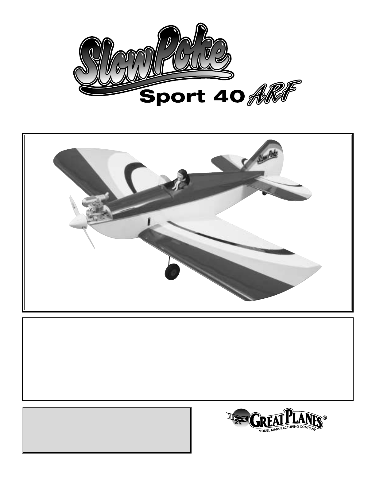
INSTRUCTION MANUAL
TM
Wingspan: 61.5 in. [1562mm]
Wing area: 1076 sq. in. [69.5 sq dm]
Weight: 6 lbs [2720g]
Wing loading: 9.6 oz./sq. ft. [29.3 g/sq dm]
Length: 49 in. [1245mm]
Radio: 4-Channel (5 Servos)
Engine: .35 to .46 two-stroke, .52 four-stroke [5.75 to 7.5cc two-stroke, 8.5cc four-stroke]
Page 2

INTRODUCTION................................................................2
SAFETY PRECAUTIONS..................................................2
DECISIONS YOU MUST MAKE ........................................3
Radio Equipment ................................................................3
Engine Recommendations.................................................3
ADDITIONAL ITEMS REQUIRED.....................................3
Hardware and Accessories................................................3
Covering Accessories.........................................................3
Adhesives and Building Supplies.......................................3
Optional Supplies and Tools...............................................3
IMPORTANT BUILDING NOTES.......................................4
ORDERING REPLACEMENT PARTS ...............................4
KIT CONTENTS .................................................................5
METRIC CONVERSION RULER.......................................5
BUILDING INSTRUCTIONS..............................................6
Wing Assembly...................................................................6
Install the Ailerons..............................................................8
Install the Aileron Servos ...................................................8
Install the Main Landing Gear..........................................10
Mount the Stab and Fin....................................................11
Mount the Engine and Fuel Tank .....................................13
Install the Radio ...............................................................15
FINAL ASSEMBLY ..........................................................17
Control Throw Adjustment................................................17
Control Surface Throws....................................................17
BALANCE Y OUR MODEL...............................................18
Balance the Model Laterally.............................................18
PREFLIGHT.....................................................................18
Charge the Batteries........................................................18
Balance the Propeller .......................................................18
Find a Safe place to Fly...................................................19
Ground Check your Model...............................................19
Range Check your Radio.................................................19
ENGINE SAFETY PRECAUTIONS.................................19
AMA SAFETY CODE ......................................................20
General.............................................................................20
Radio Control ...................................................................20
FLYING.............................................................................20
Takeoff..............................................................................20
Flight.................................................................................20
Landing.............................................................................20
The Slow Pok e Sport .40 ARF is a great follow up to our Slo w
Poke Sport .40 kit but you don't have to do the building! This
plane has all of the great flight characteristics of a sport / fun
fly airplane. This coupled with its good looks will make it a
standout at your flying field.With minimal effort you will have
this plane in the air in no time and performing to all of your
abilities.We hope you enjoy the Slow Poke Sport .40 ARF as
much as we have enjoyed bringing it to you!
For the latest technical updates or manual corrections f or the
Slow Poke Sport .40 ARF, visit the web site listed below and
select the Great Planes Slow Poke Sport .40 ARF. A “tech
notice” box will appear in the upper left corner of the page if
there is new technical information or changes to this kit.
http://www.greatplanes.com/airplanes/index.html
1.Your Slow Poke Sport .40 ARF should not be considered
a toy, but rather a sophisticated, working model that
functions very much like a full-size airplane. Because of its
performance capabilities, the Slow Poke Sport .40, if not
assembled and operated correctly, could possibly cause
injury to yourself or spectators and damage to property.
2. You must assemble the model according to the
instructions. Do not alter or modify the model, as doing
so may result in an unsafe or unflyable model. In a few
cases the instructions may differ slightly from the photos.In
those instances the written instructions should be
considered as correct.
3.You must take time to build straight, true and strong.
4. You must use an R/C radio system that is in first-class
condition and a correctly sized engine and components
(fuel tank, wheels, etc.) throughout the building process.
5.You must correctly install all R/C and other components so
that the model operates correctly on the ground and in the air .
6.You must check the operation of the model before every
flight to insure that all equipment is operating and that the
model has remained structurally sound. Be sure to check
clevises or other connectors often and replace them if they
show any signs of wear or fatigue.
7. If you are not already an experienced R/C pilot, you
should fly the model only with the help of a competent,
experienced R/C pilot.
PRO TECT YOUR MODEL,YOURSELF
& OTHERS...FOLLOW THESE
IMPORTANT SAFETY PRECAUTIONS
INTRODUCTIONTABLE OF CONTENTS
2
Page 3
Remember:T ake your time and f ollow the instructions to
end up with a well-built model that is straight and true.
If you have not flown this type of model before, we
recommend that you get the assistance of an experienced
pilot in your R/C club for your first flights. If you're not a
member of a club, your local hobby shop has information
about clubs in your area whose membership includes
experienced pilots.
In addition to joining an R/C club, we strongly recommend
you join the AMA (Academy of Model Aeronautics). AMA
membership is required to fly at AMA sanctioned clubs.There
are over 2,500 AMA chartered clubs across the country.
Among other benefits, the AMA provides insurance to its
members who fly at sanctioned sites and events .Additionally,
training programs and instructors are available at AMA club
sites to help you get started the right way. Contact the AMA
at the address or toll-free phone number below:
Academy of Model Aeronautics
5151 East Memorial Drive
Muncie, IN 47302-9252
Tele. (800) 435-9262
Fax (765) 741-0057
Or via the Internet at:
http://www.modelaircraft.org
This is a partial list of items required to finish the Slow
Poke Sport .40 ARF that may require planning or decision
making before starting to build.Order numbers are provided
in parentheses.
The Slow Poke Sport .40 ARF will require a good 4-channel
radio such as the Futaba®4VF with five servos (minimum
of 40 oz/in of torque), a Y-harness and two 6" [152mm]
servo extensions.
The recommended engine size range for the Slow Poke
Sport .40 ARF is .35 to .46 two-stroke or .52 four-stroke.
In addition to the items listed in the “Decisions Y ou Must
Make” section, the following is the list of hardware and
accessories required to finish the Slow Pok e Sport .40 ARF.
Order numbers are provided in parentheses.
❏ Propellers - Top Flite
®
Power Point®- refer to engine's
instruction manual for proper size.
❏ Fuel line - 3' medium 3/32" [2.4mm] glow fuel tubing
(GPMQ4131)
❏ 21st Centur y
®
sealing iron (COVR2700)
❏ 21st Centur y trim seal iron (COVR2750)
❏ 21st Centur y iron cover (CORQ2702)
In addition to common household tools and hobby tools, this
is the “short list” of the most important items required to
build the Slow Poke Sport .40 ARF.
Great Planes Pro™CA
and Epoxy glue are recommended.
❏ 1/2 oz. Thin Pro CA (GPMR6001)
❏ 1/2 oz. Medium Pro CA+ (GPMR6007)
❏ 6-Minute Epoxy (GPMR6045)
❏ Hobby knife (HCAR0105)
❏ #11 blades (HCAR0211)
❏ Small T-pins (HCAR5100)
❏ Builder's triangle (HCAR0480)
❏ Electric dr ill and 1/16" [1.6mm] drill bit
❏ Small Phillips and flat blade screwdrivers
❏ Pliers with wire cutter (HCAR0630)
Here is a list of optional tools mentioned in the manual that
will help you build the Slow Poke Spor t .40 ARF.
❏ Great Planes CG Machine
™
(GPMR2400)
❏ Top Flite Precision Magnetic Prop Balancer
™
(TOPQ5700)
❏ Straightedge with scale (HCAR0475)
❏ Cutting mat (HCAR0456)
❏ Masking T ape (TOPR8018)
❏ CA Debonder (GPMR6039)
❏ CA Applicator tips (GPMR6033)
❏ 1/2 oz. Thin CA (GPMR6002)
❏ 1/2 oz. Medium CA (GPMR6008)
❏ CA Applicator Tips (HCAR3780)
❏ CA Debonder (GPMR6039)
❏ CA accelerator (GPMR6034)
Optional Supplies and Tools
Adhesives and Building Supplies
Covering Accessories
Hardware and Accessories
ADDITIONAL ITEMS REQUIRED
Engine Recommendations
Radio Equipment
DECISIONS YOU MUST MAKE
We, as the kit manuf acturer, provide you with a top quality
kit and instructions, but ultimately the quality and flyability
of your finished model depends on how you build it;
therefore, we cannot in any way guarantee the
performance of your completed model and no
representations are expressed or implied as to the
performance or safety of your completed model.
3
Page 4
❏ 30-Minute Epoxy (GPMR6047)
❏ R/C-56 Canopy Glue (JOZR5007)
❏ Epoxy Brushes (GPMR8060)
❏ Mixing Sticks (GPMR8055)
❏ Threadlocker (GPMR6060)
❏ Denatured Alcohol (for epoxy clean up)
❏ Hobby Knife (HCAR0105), #11 Blades (HCAR0211)
❏ Non-elastic monofilament or Kevlar fishing line (for stab
alignment)
❏ Builders Triangle Set (HCAR0480) (for fin alignment)
❏ Masking T ape (TOPR8018)
❏ 1/16" to 1/4" drill bit set
❏ Dead Center
™
Engine Mount Hole Locator (GPMR8130)
❏ Great Planes AccuThrow
™
Deflection Gauge (for measuring
control throws, GPMR2405)
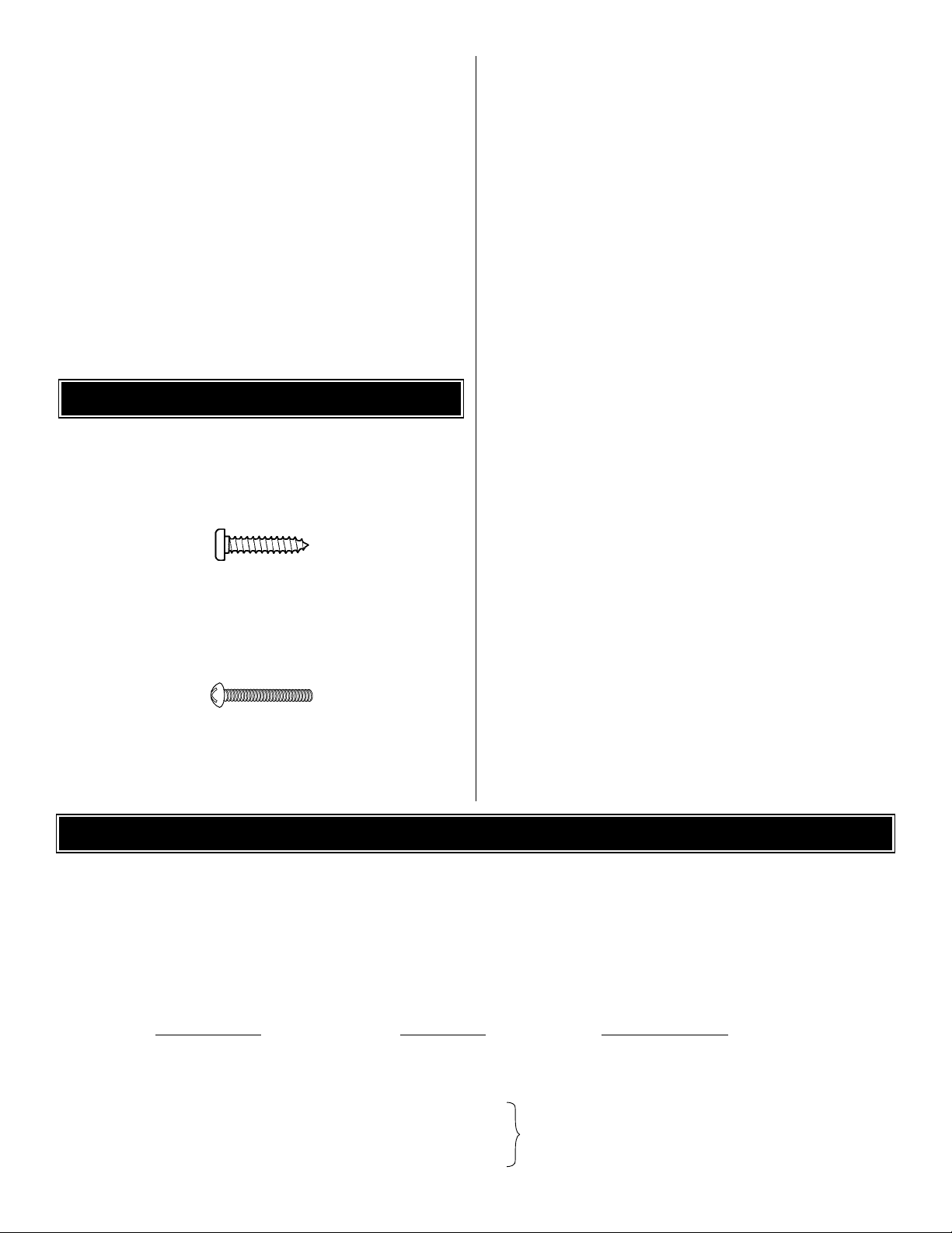
• There are two types of screws used in this kit:
Sheet metal screws are designated by a number and a
length. For example #6 x 3/4"
This is a number six screw that is 3/4" long.
Machine screws are designated by a number, threads per
inch and a length. For example 4-40 x 3/4"
This is a number four screw that is 3/4" long with
forty threads per inch.
• Whenever the term
glue
is written you should rely upon
your experience to decide what type of glue to use.When a
specific type of adhesive works best for that step, the
instructions will make a recommendation.
• Whenever just
epoxy
is specified you may use
either
30-minute epoxy or6-minute epoxy.When 30-minute epoxy
is specified it is highly recommended that you use only 30minute (or 45-minute) epoxy, because you will need the
working time and/or the additional strength.
• Photos and sketches are placed before the step they
refer to. Frequently you can study photos in following steps
to get another view of the same parts.
• The Slow Poke Sport .40 ARF is factory-covered with
Top Flite MonoKote®film. Should repairs ever be required,
MonoKote can be patched with additional MonoKote
purchased separately. MonoKote is packaged in six-foot rolls,
but some hobby shops also sell it by the foot. If only a small
piece of MonoKote is needed for a minor patch, perhaps a
fellow modeler would give you some. MonoKote is applied
with a model airplane covering iron, but in an emergency a
regular iron could be used. A roll of MonoKote includes full
instructions for application. Following are the colors used on
this model and order numbers for six foot rolls.
White TOPQ0204
Gray T OPQ0211
Sapphire Blue TOPQ0226
Black TOPQ0208
IMPORTANT BUILDING NOTES
4
To order replacement par ts for the Great Planes Slow Poke Sport .40 ARF, use the order numbers in the Replacement
Parts List that follows. Replacement par ts are available only as listed. Not all par ts are available separately (an aileron
cannot be purchased separately, but is only available with the wing kit).Replacement parts are not available from Product
Support, but can be purchased from hobby shops or mail order/Internet order firms. Hardware items (screws, nuts, bolts)
are also available from these outlets. If you need assistance locating a dealer to purchase parts, visit
www.greatplanes.com and click on “Where to Buy.” If this kit is missing parts, contact Great Planes Product Support.
Replacement Parts List
Order Number Description How to Purchase
Missing pieces ......................Contact Product Support
Instruction manual.................Contact Product Suppor t
Full-size plans.......................Not available
GPMA2265......................................Wing Kit
GPMA2266......................................Fuse Kit
GPMA2267......................................Tail Set
GPMA2268......................................Landing Gear
ORDERING REPLACEMENT PARTS
................
Contact Your Hobby
Supplier to Purchase
These Items
Page 5
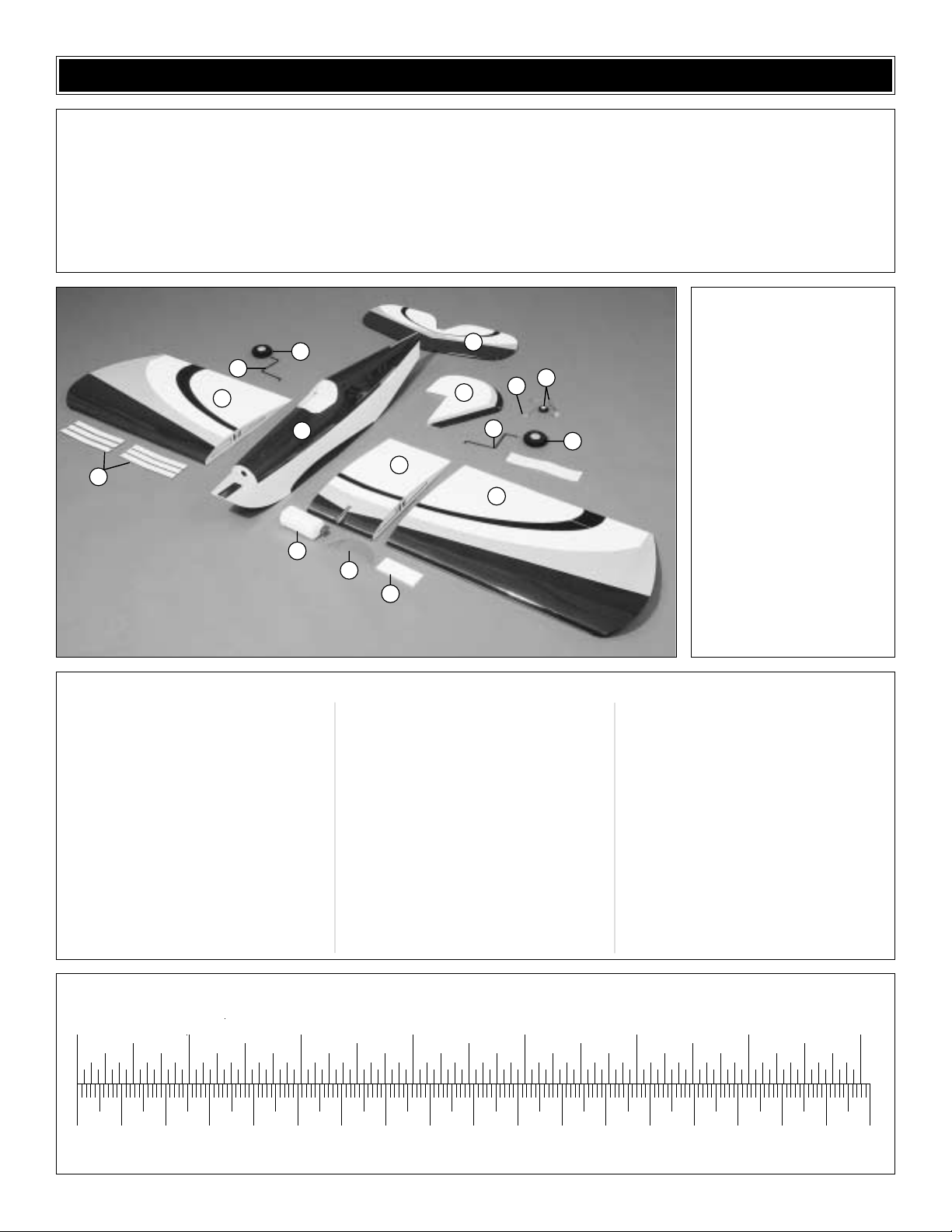
1 Outer Wings w/ Ailerons
2 Wing Center Section
3 Fuselage
4 Stab and Elevators
5 Fin and Rudder
6 Plywood Wing Joiners
7 Fuel Tank & Hardware
8 Windscreen
9 Main Landing Gear Wires
10 2-3/4" Main Wheels
11 Tail Gear with Wheel
12 Wing Bolt Plate
13 Wing Joiner Wire
(2) 1/4 - 20 Blind Nuts (Pre-installed in
fuse)
(2) 24" Grey Plastic Outer Pushrod
Tubes (Pre-installed in Fuselage)
(1) 11-3/4" Grey Plastic Outer Pushrod
Tube (Throttle)
(2) 12" .074 Wire Threaded One End
(Ailerons)
(2) 36" .074 Wire Threaded One End
(Elevator and Rudder)
(1) 17-1/2" .074 Wire Threaded One End
(Throttle)
(1) 2" x 9" Hinge Material
(1) Nylon Clevis (Rudder, Elevator,
Ailerons and Throttle)
(4) Faslink (Rudder, Elevator, Ailerons
and Throttle)
(2) Nylon 1/4 - 20 Wing Bolt (Wing)
(4) Large Nylon Control Horn (Aileron,
Rudder and Elevator
(1) Nylon Landing Gear Strap (1 tree of 4,
Landing Gear)
(5) Silicone Clevis Keepers (Rudder,
Elevator, Ailerons and Throttle
(4) 6-32 Blind Nuts (Mounting the Engine)
(4) 6-32 x 1/2" Socket Head Cap Screws
(Mounting the Engine)
(4) #6 lock washers (Mounting the
Engine)
(4) #6 washers (Mounting the Engine)
(4) 5/32" Wheel Collar (Landing Gear)
(4) 6-32 Set Screws (Wheel Collars)
(1) 3/32" Wheel Collar (Tail Wheel)
(1) 4-40 Set Screw (Tail Wheel)
(12) #2 x 1/2" Sheet Metal Screws
(Aileron Horns, Landing Gear Straps)
(4) #2 x 5/8" Machine Screws (Rudder,
Elevator)
(1) Brass Quick Connect Body (Throttle
connection)
(1) Nylon Retainer (Throttle connection)
(1) 4-40 X 1/2" Socket Head Cap Screw
(Throttle connection)
(1) White Plastic Spinner
Kit Contents
(Photographed)
Kit Contents (Not Photographed)
Before starting to build, use the Kit Contents list to take an inventory of your kit to make sure it is complete and inspect
the parts to make sure they are of acceptable quality. If any parts are missing or are not of acceptable quality, or if you
need assistance with assembly, contact Great Planes Product Support. When reporting defective or missing parts, use
the part names exactly as they are written in the Kit Contents list on this page.
Great Planes Product Support:
Phone: (217) 398-8970
Fax: (217) 398-7721
E-mail: airsupport@greatplanes.com
KIT CONTENTS
5
0" 1" 2" 3" 4" 5" 6" 7"
0 10 20 30 40 50 60 70 80 90 100 110 120 130 140 150 160 170 180
Inch Scale
Metric Scale
To convert inches to millimeters, multiply inches by 25.4
10
9
1
3
6
7
8
2
12
4
11
5
13
9
10
1
Page 6
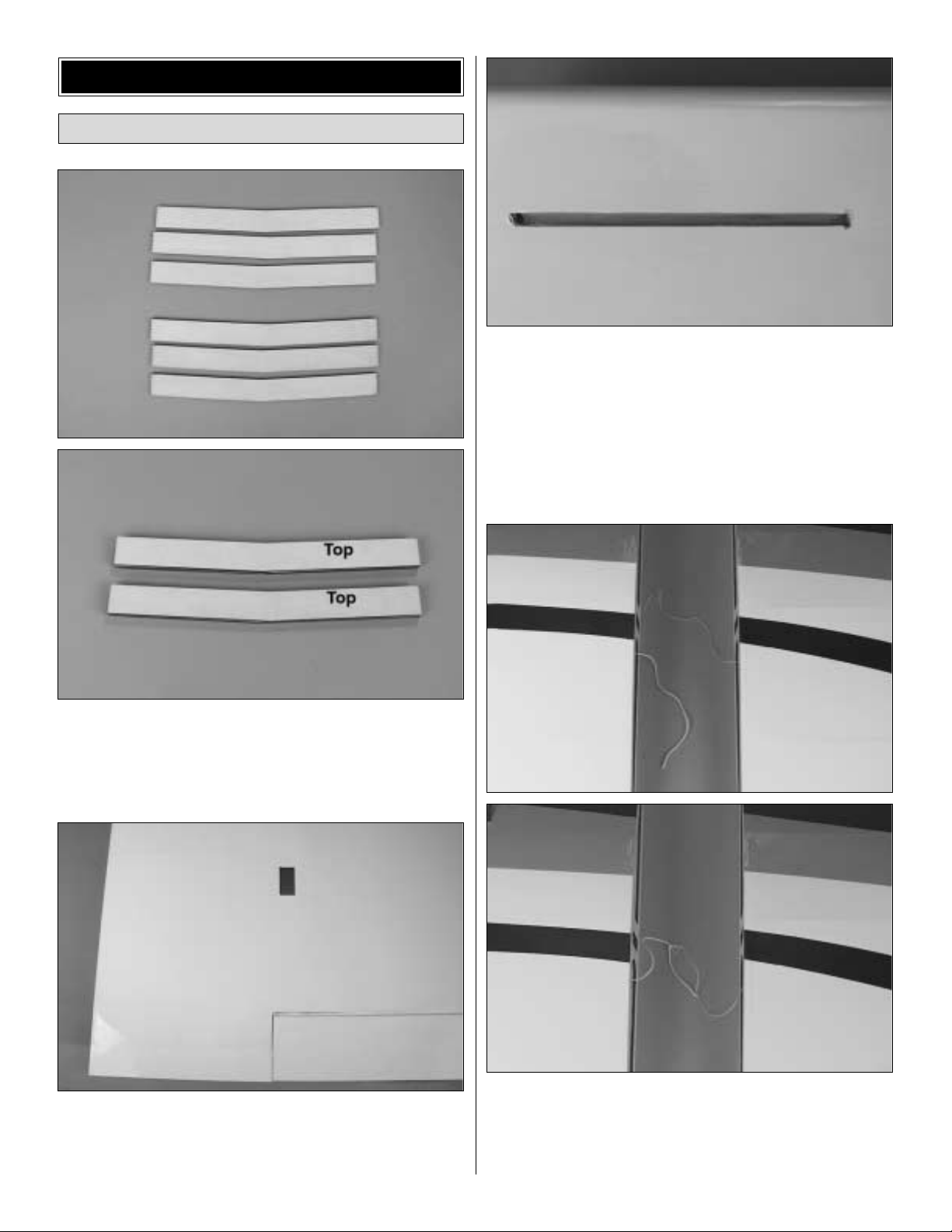
❏ 1. Locate six wing joiners. Make two wing joiners by
gluing three of the joiners together with 6-minute epoxy.
Wipe away any excess epoxy that may squeeze out. Set
them aside to allow the glue to cure.After the glue has cured
mark the top of the wing joiner as shown.
❏ 2.Locate the left and right wing panels. On the bottom of
the wing locate the aileron servo compartment. Cut the film
away with a hobby knife to reveal the servo compartment.
Iron the covering around the opening with a modeling iron.
❏ 3. Locate the slot at the leading edge of the left and right
wing for the landing gear .Cut the covering away from the slot
and iron any loose covering in place with your hobby iron.
❏ 4. Trial fit the two wing joiners into the wing center
section, into the right wing panel and left wing panel.Be
sure the wing joiners are inserted so that the top of the joiner
is against the top of the wing. When you are satisfied that
they fit remove the wings from the wing joiners.
❏ ❏ 5. The wing center section and outboard wings have
string taped to the root rib. Set the wing joiner and the right
wing panel side by side.Tie the two strings together.These
strings will be used to pull the servo wires through the wing
when you install the radio system.
Wing Assembly
BUILDING INSTRUCTIONS
6
Page 7

❏ ❏ 6.Mix 4 oz. of 30-minute epoxy in a mixing cup.Apply
a liberal amount of epoxy into the wing joiner bo x in the wing
and the wing center section. Apply epoxy to the root rib of
the wing and the wing center section. Finally, apply epoxy to
both sides, the top and the bottom of the wing joiner.Inser t
the joiner into the wing center section. Slide the right wing
panel onto the joiner.Wipe any excess epoxy from the wing
joint and clean any glue residue with rubbing alcohol. Hold
the wing and the wing center section together with masking
tape. Set the assembly aside until the glue has cured. Once
cured repeat steps 5 and 6 for the left wing panel.
❏ 7. On the top of the wing locate the two 1/4" [6mm] holes
in the wing center section at the trailing edge of the wing.Cut
away the covering material where these holes are located.
❏ 8. Locate the 2" x 4-1/2" [51 x 115mm] plywood wing
bolt plate. Draw a line on the center of the plate across the
2" width of the plate. On the bottom of the wing center
section, locate the center of the wing center section and
draw a line 3" long marking the center of the wing.
❏ 9.Place the plywood wing bolt plate on the bottom of the
wing center section at the trailing edge of the wing, aligning
the lines that you drew on the wing and the wing bolt plate.
Trace the plywood landing gear plate onto the center of the
wing with a marker.Cut away the covering inside of the lines
you have just traced onto the wing, being careful not to cut
into the wing sheeting.
❏ 10. Using 6-minute epoxy, glue the plywood wing bolt
plate to the wing center section in the area where you have
removed the covering.
❏ 11. Tur n the wing over so that you are looking at the top
of the wing. Use a 17/64" [6.7mm] drill bit to drill through the
wing bolt holes into and through the landing gear plate.
7
Page 8

❏ 1.The ailerons are taped in place to the wing. Remove
them from the wing.
❏ ❏ 2. Begin with the right aileron.On the leading edge of
the aileron you will find three hinge slots pre-cut into it.You
will also find three hinge slots cut into wing trailing edge.
Insert your hobby knife into the hinge slots to be sure there
is enough clearance for the hinges.
❏ ❏ 3. Locate the 2" x 9" [51 x 229mm] hing e material.
Cut fifteen 1" x 3/4" [25 x 19mm] hinges from the strip as
shown in the above sketch. Clip the corners of each one as
shown.This will allow easier installation of the hinges.
❏ ❏ 4. Inser t a T-pin into the center of three hinges.This
will assure that the hinge material remains centered
between the aileron and the wing. Install the hinges into the
three hinge slots in the leading edge of the aileron.
❏ ❏ 5. Once the hinges are fit to the aileron, inser t the
opposite end of the hinges into the trailing edge of the wing.
Make sure that the aileron is centered in the aileron opening
in the wing. Remove the T-pins.
❏ ❏ 6. Apply 6 drops of thin CA to the top and bottom of
each of the hinges. Allow the glue to cure and do not use
any type of CA accelerator to speed up the curing process
as this will make the hinge brittle.
❏ 7. Repeat these steps for the left wing and aileron.
❏ ❏ 1. The installation of the aileron servos requires two 6"
servo extensions.The extensions must be compatible with your
radio system and must be purchased separately. Plug the 6"
extension to the servo. Secure the connection with tape to
assure that the connectors do not accidentally come unplugged.
❏ ❏ 2. On the bottom of the right wing in the servo opening
there is a piece of string taped to the rib. Remove the string
from the rib.Tie the string to the end of the servo wires.
❏ ❏ 3. Pull the ser vo lead through the wing. Tape the end
of the servo lead to the center section of the wing to prevent
it from accidentally falling back into the wing.You may wish
to trim away the excess covering material from the hole
where the servo lead exits the wing.
Install the Aileron Servos
1"
1"
3/4"
Install the Ailerons
8
CA
THIN
Page 9

❏ ❏ 4.Install the aileron servo into the servo bay using the
hardware supplied by the radio manufacturer. Drill a 1/16"
[1.6mm] pilot hole through each of the servo mounting
holes. This will prevent the hardwood blocks from splitting
when you install the screws.
❏ ❏ 5. Temporarily plug your aileron servo into the
receiver. Turn the radio system on and allow the servo to
center itself.With the servo centered install a medium length
servo arm onto the servo so that the arm is on the left side
of the servo as shown in the photograph.(The arm will be on
the right side of the servo for the installation of the servo in
the opposite wing.)
❏ ❏ 6. From the inboard end of the aileron measure in 1"
[25mm].Draw a line on that mark across the aileron as shown.
❏ ❏ 7. Locate one of the nylon control horns. Separate
the horn and the screw mounting plate. (You can discard the
screw mounting plate.) Place the control horn on the aileron,
aligning the center of the horn on the line that you have
drawn.Position the horn at the leading edge of the aileron as
shown in the sketch.Trace the outline of the control horn onto
the aileron and mark the location of the mounting holes.
❏ ❏ 8.Drill a 1/6" [1.6mm] hole 3/8" [9.5mm] deep on both
of the mounting hole locations. Using a T-pin, poke small
holes through the iron-on covering, piercing the wood under
the covering.
❏ ❏ 9. IMPORTANT: Do not omit this step! Using thin CA
saturate the small pin holes and the holes you drilled for the
mounting screws.Allow the CA to cure. Install a #2 x 3/8" [#2
x9.5mm] sheet metal screw into each of the mounting holes.
Remove the screw and put a couple of drops of thin CA into
the screw holes and allow the CA to cure.
Correct Incorrect
9
Page 10

❏ ❏ 10. Mount the control horn to the aileron with two
#2 x 3/8" [#2 x9.5mm] sheet metal screws.
❏ ❏ 11. Locate a .074 x 12" pushrod wire threaded on
one end. Screw a nylon clevis onto the threaded end of the
wire 25 turns. Install a silicone clevis keeper onto the clevis.
Install the clevis on the aileron control horn.
❏ ❏ 12. Be sure the aileron servo is centered (plug the
servo into the receiver and turn the radio on to re-center it
properly if you are unsure). Center the aileron and align the
wire pushrod with the hole in the end of the servo arm.Using
a marker, mark the location where the wire aligns with the
hole in the servo arm. On that mark make a 90 degree bend.
From the bend measure up 3/8" [9.5mm].Cut off the excess
pushrod wire.
❏ ❏ 13.Install the wire into the hole in the servo arm using
a nylon FasLink as shown in the sketch.
❏ ❏ 14.Repeat these steps for the servo installation in the
left wing.
❏ 15. Having separate servos on each aileron could be new
to some modelers.When connecting two separate servos to a
single channel on your radio you will either need to plug them
into a Y-harness or if your radio has the capability of mixing two
separate channels to the aileron you can connect the servos
that way. Review your radio instruction manual to see if it has
this capability .If you are going to be using a Y-harness plug the
servos into the connector. Tape the servo leads to the
connector to prevent them from coming unplugged.
❏ ❏ 1.Locate the wire landing gear. Both of them are the
same so there is no left or right. Install the wire into the slot
in the bottom of the right wing.
❏ ❏ 2. Locate the nylon landing gear straps. Place two
straps over the wire as shown. Drill a 1/16" [1.6mm] pilot
hole for each hole in the landing gear strap .Install the straps
with two #2 x 1/2" [#2 x 13mm] sheet metal screws for each
landing gear strap.
❏ ❏ 3. Locate two 5/32" [4mm] wheel collars, two 4-40
set screws and one of the 2-3/4" foam wheels. Install a
wheel collar, the wheel and then another wheel collar onto
the landing gear wire. Install a set screw into each wheel
collar, tightening it to keep the wheel collars in place.When
locating the wheel collars be sure to leave enough room for
the wheel to spin freely.
❏ 4. Repeat these steps for the left wing.
Install the Main Landing Gear
FasLink
2-56 (.074") Pushrod Wire
Servo Horn
10
Page 11

❏ 1. Cut the covering from the slots in the fuse for the stab,
fin and guide tubes for the pushrods.
❏ 2.Fit the stab into the fuse.Center the trailing edge by taking
accurate measurements as shown in X = X in the sketch.
❏ 3. Bolt the wing to the fuse. Place the model in a building
stand (such as a Robart Super Stand II, ROBP1402). Stand
five to ten feet behind the model and vie w the stab and wing.
If the stab and wing align with each other, proceed to the ne xt
step.If the stab and wing do not align, place a weight on the
“high” side of the stab to bring it into alignment. If much
weight is required, remove the stab and sand the slot in the
fuse where the stab fits until the stab aligns with the wing.
❏ 4. Insert a T-pin into the top of the fuse centered in the
middle stringer at the front of the wing. Tie a small loop in
one end of a 42" piece of non-elastic string such as K & S
#801 Kevlar thread (K+SR4575). Slip the loop in the str ing
over the T-pin.
❏ 5. Fold a piece of masking tape over the other end of the
string and draw an arrow on it.Slide the tape along the string
and align the arrow with one end of the stab as shown in the
photo. Swing the string over to the same position on the
other end of the stab.While keeping the stab centered from
side-to-side, adjust the stab and slide the tape along the
string until the arrow aligns with both sides. Be cer tain the
stab remains centered from side-to-side during this process.
❏ 6. Use a fine-point felt-tip pen such as a Top Flite Panel
Line Pen (TOPQ2510) to mar k the outline of the fuse onto
the top and bottom of the stab.
Mount the Stab and Fin
11
X
X
X = X
Page 12

❏ 7. Remove the stab from the fuse. Use a sharp #11
hobby knife or use the Expert Tip that follows to cut the
covering from the stab along the lines you marked.Use care
to cut only into the covering and not into the wood.
How to cut covering from balsa.
Use a Hobbico Hot Knife (HCAR0770) or soldering iron to
cut the covering from the stab.The tip of the soldering iron
doesn't have to be sharp, b ut a fine tip does work best.Allow
the iron to heat fully. Use a straightedge to guide the
soldering iron at a rate that will just melt the covering and not
burn into the wood. The hotter the soldering iron, the faster
it must travel to melt a fine cut.Peel off the covering.
❏ 8. The same as you did for the wing, cut the covering from
the hinge slots in the stab and elevators and the fin and rudder .
Be sure to clear out the slot with the back edge of your hobby
knife.There are three slots in the rudder and in both elevators
and two hinge slots in the fin.There is also a hinge slot in the
fuse that aligns with the bottom hinge slot in the rudder.
❏ 9. Use six more CA hinges from the CA hinge strip.
Temporarily join the elevators to the stab with the hinges.
❏ 10. Position the elevator joiner wire, evenly spaced,
over both elevators as shown in the photo. Mark the ends of
the joiner wire onto the elevators and e xtend this mark to the
leading edge of the elevators.
❏ 11. Drill a 1/8" hole through the LE of both elevators at
the marks you made. Use a Great Planes Groove Tube™or
a 1/8" brass tube sharpened on the end to cut a groove in
the LE of the elevators to accommodate the joiner wire.Test
fit the elevators to the stab with the joiner wire. “Tweak” the
joiner wire if necessary to get both elevators even.
❏ 12. Remove the elevators and elevator joiner wire from
the stab.
❏ 13. Use 30-minute epoxy to glue the stab into the fuse.
For the most strength, apply epoxy to both sides of the stab
and inside the fuse where the stab fits. Slide the stab and
the ele
vator joiner wire
into position. Wipe away residual
epoxy with a tissue dampened with alcohol. If the stab
required a weight on one side or the other to align it with the
fuse, reposition the weight.Use the pin and string to confirm
stab alignment. Allow the epoxy to cure.
12
Page 13

❏ 14. Thoroughly coat the insides of the holes in the
elevators for the joiner wire with 30-minute epoxy. Also coat
the ends of the joiner wire that go into the elevators .Join the
elevators to the stab and the joiner wire with the hinges.
Wipe away excess epoxy before it hardens. The same as
you did the ailerons, permanently join the elevators to the
stab by gluing in the hinges with thin CA.
❏ 15. Use a #11 blade or a small razor saw to cut a slot in
the aft end of the fuse for the nylon bearing on the tail gear
wire.Test fit the tail gear wire into the fuse as shown.
❏ 16. Fit the fin in the fuse. Just the same as you did the
stab, mark the outline of the fuse onto the fin, then use a #11
hobby knife or the soldering iron technique to remove the
covering from the fin where it slides onto the fuse top.Glue
the fin into position with 30-minute epoxy using a builder’s
square to make certain the fin is vertical. If necessary, pull
the fin to one side or the other with masking tape until the fin
is perpendicular to the stab.
❏ 17. Apply petroleum jelly to the nylon wheel bearing
where the wire passes through. This will prevent the wire
from being glued to the bearing.Permanently join the rudder
to the fin using 30-minute epoxy to glue the “arm” por tion of
the tail gear wire into the hole in the rudder. Then use thin
CA to glue in the hinges.
❏ 18.Install the tailwheel onto the 3/32" [2.4mm] tailwheel
wire.Retain the wheel by installing a 4-40 set screw into the
3/32" [2.4mm] wheel collar and then lock the wheel collar in
place with the set screw.
❏ 1. The engine mounting plate on the Slow Poke Sport .40
ARF was designed to accommodate most brands of .35 to .46
engines. As it is cut now, the mount will hold most brands of
.35 engines.If you are using a .40 or .46 engine you will have
to cut the mounting plate to accommodate the engine you
have chosen to use.Cut the mounting plate to fit your engine.
❏ 2. Cut the fuselage to accommodate the front of your
engine. A Moto-Tool™with a rotary drum makes this a pretty
easy task.
Mount the Engine and Fuel Tank
13
Page 14

❏ 3. On the bottom of the engine compartment cut away
the covering from the hole (this hole can be seen by looking
into the front of the fuselage from the top) in the bottom of
the fuselage. This hole allows any fuel that may enter the
front of the fuselage to drain out.
❏ 4. Use small clamps or another method to temporarily
secure the engine to the engine mounting plate with the
front of the engine thrust washer 4" [102mm] from the
firewall. Use a Great Planes Dead Center™Engine Mount
Hole Locator (GPMR8130) or another method to mark the
engine mount holes onto the engine mounting plate.
❏ 5. Drill a 5/32" [4mm] holes on each of the marks you
have made.
❏ 6.Locate four 6/32 blind nuts.Cut one side flat as shown.
❏ 7. On the underside of the engine mounting plate insert
the blind nuts into the holes you have drilled. When you
position them be sure that the flat side of the blind nut is in
line with the edge of the engine mounting plate. This will
allow clearance for the side of the engine as it is slid onto the
engine mounting plate.
❏ 8. Mount the engine to the engine mounting plate with
four 6-32 x 1" SHCS (socket-head cap screws), #6 lock
washers and #6 flat washers.
❏ 9. Locate the 11-3/4" [298mm] gray plastic tube. Inser t it
through the hole on the right side of the fuselage and
through the pre-drilled hole located on the right side of the
former in the engine compartment of the fuselage. Apply a
small amount of 5 minute epoxy to the tube to keep it in
place. Note: If you are installing a 4-cycle engine you may
find it necessary to drill a hole in the firewall to
accommodate the gray plastic tube in a different location
other than the pre-drilled hole in the firewall.
❏ 10. Assemble the stopper and tubes as shown in the
photo.Inser t the completed stopper assembly into the tank.
Tighten the screw to expand the stopper, thus sealing the
tank. Be certain the fuel line weight (clunk) at the end of the
14
Page 15

fuel line inside the tank does not contact the rear of the tank.
Otherwise, the line may become stuck during flight and
discontinue fuel flow. Remember (or use a felt-tip pen to
mark) which tube is the fuel pick-up tube and which tube is
the vent (that will be connected to the pressure fitting on the
engine muffler).
❏ 11. Install the tank in the fuse. Fit the neck through the
hole in the firewall. Be certain the vent tube inside the tank
is pointing upward.
❏ 12. Hold the tank in place on the tank supports by gluing
a scrap piece of balsa (not included) across the former.
❏ 13. Make the throttle pushrod by threading a nylon
clevis approximately 25 full turns onto the end of a 12"
pushrod. Slide a silicone clevis keeper over the end of the
clevis. Inser t the end of the wire into the gray plastic tube
you previously installed. Next connect the clevis to the
throttle arm on the engine.
❏ 14. Install the engine muffler. Install silicone fuel line (not
included) from the fuel tank pick up line to the carburetor and
from the fuel tank vent line to the muffler.
❏ 1.Make the elevator and rudder pushrods by threading
two nylon clevises approximately 25 full turns onto the end
of two 36" pushrods. Slide a silicone clevis keeper over the
end of the clevis. Connect each clevis to a large nylon
control horn.
❏ 2.Slide the pushrods into the guide tubes through the aft
end of the fuse. Drill 3/32" holes through the rudder and
elevator and mount the horns with 2-56 x 5/8" [2-56 x
15.9mm] screws and the nylon mounting plates on the other
side of the control surface. Attach the clevis to the control
horn. Slide the silicone clevis keeper over the clevis.
Correct Incorrect
Install the Radio
15
Page 16

Refer to this photo while mounting the servos.
❏ 3. Test fit the rudder, elevator and throttle servos in the
1/8" plywood servo tray. Make modifications to the tray if
necessary to fit the servos.
❏ 4. Place the servos in the tray. Mount them with the
hardware provided with the radio system.Center the servos
and position the servo arms as shown in the photo at step
#3. Center the elevator and rudder. Bend the elevator and
rudder pushrods over the holes in the servo arms. Cut the
wires so they can be connected to the servos with a nylon
Faslink as shown in the sketch.
❏ 5. Attach the throttle to the ser vo using the brass screw
lock connector, nylon retainer and 4-40 set screw.Turn
your radio system on.Push the throttle stick to full open. Be
sure the carburetor is also fully opened. Tighten the set
screw onto the throttle wire.
❏ 6. Wrap the batter y pack and receiver in at least 1/4" of
R/C foam rubber and install them in the fuselage. Securely
hold the battery pack and receiver in position with a balsa
stick glued between the fuse sides (not shown). Simply
stuffing the receiver and battery pack in place with additional
foam rubber is not a secure method of holding them in place.
❏ 7. If you did not previously install a Y-harness to the
ailerons, connect a Y -harness (HCAM2500 for Futaba J) to the
aileron servo wires in the wing. Secure the connections with
heat shrink tubing, tape or clips intended for that purpose.
❏ 8. Mount the receiver on/off switch. A Great Planes
Switch & Charge Jack Mounting Set (GPMM1000, not
included) was used on this model. Be certain it is in a
location away from engine exhaust.
❏ 9. Make certain all the servo arms are secured to the
servos with the screws that came with them and that all the
clevises have retainers on them.
❏ 10. Uncoil the receiver antenna and guide it out of the
fuselage and connect it to the fin.We drilled a 7/32" [5.6mm]
16
FasLink
2-56 (.074") Pushrod Wire
Servo Horn
RETAINER
Page 17

hole in the bottom of the fuselage just behind the radio
compartment and inserted a piece of fuel tubing (this acts as
a strain relief) into the hole. Then, we ran the antenna wire
out of the inside of the fuselage through the fuel tubing. (The
antenna wire should run through an unused servo arm and
the arm should be positioned just below the hole you drilled
in the fuselage.) Next, we cut an unused servo arm as
shown, allowing the antenna wire to be attached to a rubber
band. Finally, the rubber band was wrapped around the
tailwheel wire.
❏ 1. Install the spinner included with the kit and a propeller
appropriate for your choice of engine.
By moving the position of the clevis at the control horn
toward the outermost hole, you will decrease the amount of
throw of the control surface. Moving it toward the control
surface will increase the amount of throw. If these
adjustments don't accomplish the job, you ma y need to w ork
with a combination of adjustments by also repositioning the
pushrod at the servo end. Moving the pushrod towards the
center of the servo horn will decrease the control surface
throw, outward will increase it.
Note: Throws are measured at the widest part of the
elevators , rudder and ailerons.We recommend the following
control surface throws as a starting point:
One of the leading causes of crashes is flying an airplane with
its control throws set differently from those recommended in
the instructions. The Great Planes AccuThrow (GPMR2405)
lets you quickly and easily measure actual throws first, so y ou
can make necessary adjustments before you fly. Large, noslip rubber feet provide a firm grip on covered surfaces
without denting or marring the finish. Spring tension holds
AccuThrow's plastic ruler steady by each control surface.
Curved to match control motions, the ruler provides exact
readings in both standard or metric measurements. Make
sure the control surfaces move in the proper direction as
illustrated in the following sketch:
CARBURETOR WIDE OPEN
RUDDER MOVES RIGHT
LEFT AILERON MOVES DOWN
RIGHT AILERON MOVES UP
ELEVATOR MOVES UP
4-CHANNEL
TRANSMITTER
(STANDARD MODE 2)
4-CHANNEL RADIO SETUP
TRANSMITTER
4-CHANNEL
TRANSMITTER
4-CHANNEL
TRANSMITTER
4-CHANNEL
These are the recommend control surface throws:
High Rate Low Rate
ELEVATOR: 7/16" [11mm] up 1/4" [6mm] up
7/16" [11mm] down 1/4" [6mm] down
RUDDER: 1-1/2" [38mm] right 1-1/2" [38mm] right
1-1/2" [38mm] left 1-1/2" [38mm] left
AILERONS: 1" [25mm] up 3/4" [19mm] up
1" [25mm] down 3/4" [19mm] down
Control Surface Throws
Control Thro w Adjustment
FINAL ASSEMBLY
17
Page 18

Note: This section is VERY important and must NOT be
omitted! A model that is not properly balanced will be
unstable and possibly unflyable.
❏ 1. The balance point (C.G.) is located 4-5/8" [116mm]
back from the leading edge of the wing. Balance your
Slow Poke Sport .40 ARF using a Great Planes C.G.
Machine Airplane Balancer (GPMR2400) for the most
accurate results.This is the point at which your model should
balance for your first flights.After initial trim flights and when
you become more acquainted with your Slow Poke Sport .40
ARF, you may wish to experiment by shifting the balance up
to 3/8" [9.5mm] forward or backward to change its flying
characteristics.Moving the balance forward may impro ve the
smoothness and stability, but the model may then require
more speed for takeoff and may become more difficult to
slow for landing. Moving the balance aft makes the model
more agile with a lighter, snappier feel. In any case, please
start at the location we recommend. Do not at any time
balance your model outside the recommended range.
❏ 2.With all par ts of the model installed (ready to fly) and
an empty fuel tank, block up the tail as necessary to level the
stab.Lift the model at the desired balance point and observe
the tail of the aircraft. If the tail drops, the model is “tail
heavy” and you must add weight to the nose to balance the
model.If the nose drops, it is “nose heavy”and you must add
weight to the tail to balance the model.
Note: Nose weight may be easily installed by using a
spinner weight. Tail weight may be added by using Great
Planes (GPMQ4485) “stick-on” lead weights.
IMPORTANT: Do not confuse this procedure with
checking the C.G. or balancing the airplane fore and aft.
Now that you have the basic airplane nearly completed, this
is a good time to balance the airplane laterally (side-to-side).
Here is how to do it:
❏ 1. Make sure the fuel tank is empty.
❏ 2. With the wing level, lift the model by the engine
propeller shaft and the fin post (this may require two
people). Do this several times.
❏ 3. If one wing always drops when you lift the model, it
means that side is heavy. Balance the airplane by adding
weight to the opposite, lighter wing tip.
Note: An airplane that has been laterally balanced will track
better in loops and other maneuvers.
At this time check all connections including servo horn
screws, clevises, servo cords and extensions.
Follow the battery charging procedures in your radio
instruction manual.You should always charge your transmitter
and receiver batteries the night before you go flying and at
other times as recommended by the radio manufacturer.
Carefully balance your propellers before flying. An
unbalanced prop is the single most significant cause of
vibration. Not only may engine mounting screws vibrate out,
possibly with disastrous effect, but vibration may also
damage your radio receiver and battery. Vibration may
cause your fuel to foam, which will, in turn, cause your
engine to run lean or quit.
Balance the Propeller
Charge the Batteries
PREFLIGHT
Balance Your Model Laterally
BALANCE Y OUR MODEL
18
4-5/8"
Page 19

We use a Top Flite Precision Magnetic Prop Balancer
(TOPQ5700) in the workshop and keep a Great Planes
Fingertip Balancer (GPMQ5000) in our flight box.
We strongly suggest that the best place to fly is an AMA
chartered club field. Ask the AMA or your local hobby shop
dealer if there is a club in your area and join.Club fields are
set up for R/C flying and that makes your outing safer and
more enjoyable. The AMA address and telephone number
are in the front of this manual.If a club and flying site are not
available, find a large, grassy area at least 6 miles away
from houses, buildings and streets and any other R/C radio
operation like R/C boats and R/C cars. A schoolyard may
look inviting but is too close to people, power lines and
possible radio interference.
Inspect your radio installation and confirm that all the control
surfaces respond correctly to the transmitter inputs. The
engine operation must also be checked by confirming that
the engine idles reliably, transitions smoothly and rapidly to
full power and maintains full power, indefinitely.The engine
must be “broken-in” on the ground by running it for at least
two tanks of fuel. Follow the engine manufacturer's
recommendations for break-in. Make sure that all screws
remain tight, that the hinges are secure and that the prop is
on tight.
Whenever you go to the flying field, check the operational
range of the radio before the first flight of the da y.First, make
sure no one else is on your frequency (channel). With your
transmitter and receiver on, you should be able to walk at
least 100 feet away from the model and still have control.
While you work the controls, have a helper stand by your
model and tell you what the control surfaces are doing.
Repeat this test with the engine running at various speeds
with a helper holding the model. If the control surfaces are
not always responding correctly, do not fly! Find and correct
the problem first. Look for loose servo connections or
corrosion, loose bolts that may cause vibration, a defective
on/off switch, low battery voltage or a defective receiver
battery, a damaged receiver antenna, or a receiver crystal
that may have been damaged from a previous crash.
Note: Failure to follow these safety precautions may result
in severe injury to yourself and others.
Keep all engine fuel in a safe place, away from high heat,
sparks or flames, as fuel is very flammable. Do not smoke
near the engine or fuel; and remember that the engine
exhaust gives off a great deal of deadly carbon monoxide.
Do not run the engine in a closed room or garage.
Get help from an experienced pilot when learning to
operate engines.
Use safety glasses when starting or running engines.Do not
run the engine in an area of loose gravel or sand; the
propeller may throw such material in your face or eyes.
Keep your f ace and body as well as all spectators a wa y from the
plane of rotation of the propeller as you start and run the engine.
Keep these items away from the prop: loose clothing, shir t
sleeves, ties, scarfs, long hair or loose objects such as
pencils or screwdrivers that may fall out of shirt or jacket
pockets into the prop.
Use a “chicken stick” or electric starter to star t the engine.
Do not use your fingers to flip the propeller .Make certain the
glow plug clip or connector is secure so that it will not pop
off or otherwise get into the running propeller.
Make all engine adjustments from behind the rotating propeller .
The engine gets hot! Do not touch it during or right after
operation. Make sure fuel lines are in good condition so fuel
will not leak onto a hot engine, causing a fire.
To stop a glow engine, cut off the fuel supply by closing off
the fuel line or following the engine manufacturer's
recommendations. Do not use hands, fingers or any other
body part to tr y to stop the engine. Do not throw anything
into the propeller of a running engine.
ENGINE SAFETY PRECAUTIONS
Range Check Your Radio
Ground Check the Model
Find a Safe Place to Fly
19
Page 20

Read and abide by the following Academy of Model
Aeronautics Official Safety Code:
1.I will not fly my model aircraft in sanctioned ev ents, air shows ,
or model flying demonstrations until it has been proven to be
airworthy by having been previously successfully flight tested.
2. I will not fly my model aircraft higher than approximately
400 feet within 3 miles of an airport without notifying the
airpor t operator. I will give right of way to and avoid flying in
the proximity of full-scale aircraft. Where necessary an
observer shall be used to supervise flying to avoid having
models fly in the proximity of full-scale aircraft.
3. Where established, I will abide by the safely rules for the
flying site I use and I will not willfully and deliberately fly my
models in a careless, reckless and/or dangerous manner.
4. I will not fly my model unless it is identified with my name
and address or AMA number, on or in the model.
5. I will not operate models with pyrotechnics (any device
that explodes, burns, or propels a projectile or any kind).
1. I will have completed a successful radio equipment
ground check before the first flight of a new or repaired
model airplane.
2. I will not fly my model aircraft in the presence of
spectators until I become a qualified flier, unless assisted b y
an experienced helper.
3. I will perform my initial turn after takeoff away from the pit
or spectator areas and I will not thereafter fly over pit or
spectator areas, unless beyond my control.
4. I will operate my model using only radio control frequencies
currently allowed by the F ederal Communications Commission.
The Slow Poke Sport .40 ARF is a fun and enjoyable plane
to fly. It is very predictable when balanced at the
recommended C.G.and the control throws are set at the low
rate recommendation. Set up this way you will find that it
performs most mild aerobatic maneuvers with ease. Move
the C.G.back and step up to the high rate control throws and
you will have a very responsive fun flying model!
The Slow Poke Sport .40 ARF has no bad ground handling
characteristics. Simply line up on the runway, advance the
throttle slowly, make steering corrections as needed with the
rudder and you will be airborne in about 50 feet.
Once airborne you will find that the Slow Poke Sport .40
ARF performs slow flight maneuvers as easily as it perf orms
at faster speeds. Tight loops, large loops, slow rolls, fast
rolls, inverted flight are all easily done with the Slow Poke
Sport .40 ARF. You will find slow flight especially fun as the
large wing really allows it to slow nicely!
When it comes time to land the Slow Poke Sport .40 ARF,
you will find it is as predictable to land as it was to fly.Simply
line it up on the runway and slowly decrease the speed.
When you are over the runway, drop the throttle and flare to
a three point landing!
Have a ball! But alwa ys sta y in control and fly in a safe manner .
Landing
CAUTION (THIS APPLIES TO ALL R/C AIRPLANES):
If, while flying, you notice any unusual sounds, such as a
low-pitched “buzz,” this may be an indication of control
surface “flutter.” Because flutter can quickly destroy
components of your airplane, any time you detect flutter
you must immediately cut the throttle and land the
airplane! Check all servo grommets for deterioration (this
will indicate which surface fluttered) and make sure all
pushrod linkages are slop-free. If it fluttered once, it will
probably flutter again under similar circumstances unless
you can eliminate the slop or flexing in the linkages.Here
are some things which can result in flutter: Excessive
hinge gap;Not mounting control horns solidly; Sloppy fit of
clevis pin in horn; Elasticity present in flexible plastic
pushrods; Side-play of pushrod in guide tube caused by
tight bends; Sloppy fit of Z-bend in servo arm; Insufficient
glue used when gluing in the elevator joiner wire or aileron
torque rod; Excessive “play” or “backlash” in ser vo gears;
and Insecure servo mounting.
Flying
Takeoff
FLYING
Radio Control
General
AMA SAFETY CODE (EXCERPT)
 Loading...