

Great Planes GPMA1205 User Manual
INSTRUCTION MANUAL
SPECIFICATIONS
Wingspan: 56 in [1420mm]
Wing Area: 543 in
Wing Loading: 28−31 oz/ft
2
[35 dm2]
2
[85−95 g/dm2]
WARRANTY
Great Planes® Model Manufacturing Co. guarantees this kit to
be free from defects in both material and workmanship at the
date of purchase. This warranty does not cover any component
parts damaged by use or modification. In no case shall Great
Planes’ liability exceed the original cost of the purchased kit.
Further, Great Planes reserves the right to change or modify this
warranty without notice.
In that Great Planes has no control over the final assembly or
material used for final assembly, no liability shall be assumed nor
accepted for any damage resulting from the use by the user of
the final user-assembled product. By the act of using the
user-assembled product, the user accepts all resulting liability.
If the buyer is not prepared to accept the liability associated
with the use of this product, the buyer is advised to return
Length: 50 in [1270mm]
Weight: 6.5−7.25 lb [2950−3290 g]
Radio: 4-channel minimum with
4-5 servos & standard size receiver
Engine: .40-.55 cu in [7-9cc] two-stroke,
.70 cu in [11.5cc] four-stroke,
RimFire .55 (42-60-480)
brushless out-runner motor
this kit immediately in new and unused condition to the
place of purchase.
To make a warranty claim send the defective part or item to
Hobby Services at the address below:
Hobby Services
3002 N. Apollo Dr. Suite 1
Champaign IL 61822 USA
Include a letter stating your name, return shipping address, as
much contact information as possible (daytime telephone
number, fax number, e-mail address), a detailed description of
the problem and a photocopy of the purchase receipt. Upon
receipt of the package the problem will be evaluated as quickly
as possible.
READ THROUGH THIS MANUAL BEFORE STARTING CONSTRUCTION. IT CONTAINS IMPORTANT
INSTRUCTIONS AND WARNINGS CONCERNING THE ASSEMBLY AND USE OF THIS MODEL.
Champaign, Illinois
(217) 398-8970, Ext 5
airsupport@greatplanes.com
Entire Contents © 2010 GPMA1205 Mnl
TABLE OF CONTENTS
INTRODUCTION . . . . . . . . . . . . . . . . . . . . . . . . . . . . . . . . 2
AMA . . . . . . . . . . . . . . . . . . . . . . . . . . . . . . . . . . . . . . . 2
SAFETY PRECAUTIONS . . . . . . . . . . . . . . . . . . . . . . . . . 2
DECISIONS YOU MUST MAKE. . . . . . . . . . . . . . . . . . . . . 3
Radio Equipment . . . . . . . . . . . . . . . . . . . . . . . . . . . . . 3
Power System Recommendations . . . . . . . . . . . . . . . . 3
Propeller. . . . . . . . . . . . . . . . . . . . . . . . . . . . . . . . . . . . 3
Batteries and Charger . . . . . . . . . . . . . . . . . . . . . . . . . 3
ADDITIONAL ITEMS REQUIRED . . . . . . . . . . . . . . . . . . . 4
Required Hardware and Accessories . . . . . . . . . . . . . 4
Adhesives and Building Supplies. . . . . . . . . . . . . . . . . 4
Optional Supplies and Tools. . . . . . . . . . . . . . . . . . . . . 4
Building Stand . . . . . . . . . . . . . . . . . . . . . . . . . . . . . . . 4
IMPORTANT BUILDING NOTES. . . . . . . . . . . . . . . . . . . . 5
KIT INSPECTION. . . . . . . . . . . . . . . . . . . . . . . . . . . . . . . . 5
ORDERING REPLACEMENT PARTS. . . . . . . . . . . . . . . . 5
KIT CONTENTS. . . . . . . . . . . . . . . . . . . . . . . . . . . . . . . . . 6
PREPARATIONS . . . . . . . . . . . . . . . . . . . . . . . . . . . . . . . . 6
ASSEMBLE THE WINGS. . . . . . . . . . . . . . . . . . . . . . . . . . 6
ASSEMBLE THE T AIL SECTION. . . . . . . . . . . . . . . . . . . 10
INSTALL THE POWER SYSTEM . . . . . . . . . . . . . . . . . . 11
Glow Engine Installation. . . . . . . . . . . . . . . . . . . . . . . 11
Brushless Motor Installation. . . . . . . . . . . . . . . . . . . . 14
FINISH THE MODEL . . . . . . . . . . . . . . . . . . . . . . . . . . . . 16
Apply the decals. . . . . . . . . . . . . . . . . . . . . . . . . . . . . 18
GET THE MODEL READY TO FLY . . . . . . . . . . . . . . . . . 19
Install and Operate the Motor Battery
(Brushless Only) . . . . . . . . . . . . . . . . . . . . . . . . . 19
Check the Control Directions . . . . . . . . . . . . . . . . . . . 19
Set the Control Throws. . . . . . . . . . . . . . . . . . . . . . . . 20
Balance the Model (C.G.). . . . . . . . . . . . . . . . . . . . . . 20
Balance the Model Laterally. . . . . . . . . . . . . . . . . . . . 21
PREFLIGHT. . . . . . . . . . . . . . . . . . . . . . . . . . . . . . . . . . . 21
Identify Your Model. . . . . . . . . . . . . . . . . . . . . . . . . . . 21
Charge the Batteries . . . . . . . . . . . . . . . . . . . . . . . . . 21
Balance Propellers. . . . . . . . . . . . . . . . . . . . . . . . . . . 21
Ground Check . . . . . . . . . . . . . . . . . . . . . . . . . . . . . . 21
Range Check . . . . . . . . . . . . . . . . . . . . . . . . . . . . . . . 21
ENGINE SAFETY PRECAUTIONS . . . . . . . . . . . . . . . . . 22
AMA SAFETY CODE (excerpts) . . . . . . . . . . . . . . . . . . . 22
General . . . . . . . . . . . . . . . . . . . . . . . . . . . . . . . . . . . 22
Radio Control . . . . . . . . . . . . . . . . . . . . . . . . . . . . . . . 22
CHECK LIST . . . . . . . . . . . . . . . . . . . . . . . . . . . . . . . . . . 23
FLYING. . . . . . . . . . . . . . . . . . . . . . . . . . . . . . . . . . . . . . . 23
Fuel Mixture Adjustments . . . . . . . . . . . . . . . . . . . . . 23
Takeoff . . . . . . . . . . . . . . . . . . . . . . . . . . . . . . . . . . . . 24
Flight . . . . . . . . . . . . . . . . . . . . . . . . . . . . . . . . . . . . . 24
Landing . . . . . . . . . . . . . . . . . . . . . . . . . . . . . . . . . . . 24
glue-free assembly! And because the parts are bolted together,
replacement parts can be installed in a snap should your plane
suffer from a rough or unexpected landing.
The P-51 fl ies great with both glow and electric power systems.
Like most current Great Planes models, the P-51 includes all
the necessary hardware to mount your brushless motor and
ESC. A magnetic battery hatch makes battery changing take
only a moment. With economy in mind, only low-cost standard
servos are needed with a minimum of servo extensions. Even
a pre-assembled plywood brushless motor mount is included
to save you the cost of purchasing an aluminum mount. In the
air, the P-51 is a great sport fl yer for both the veteran pilot or
as a fi rst low-wing plane.
For the latest technical updates or manual corrections to the
Great Planes Sport Scale P-51 ARF, visit the Great Planes
web site at www.greatplanes.com. Open the “Airplanes” link,
then select the Sport Scale P-51 ARF. If there is new technical
information or changes to this model a “tech notice” box will
appear in the upper left corner of the page.
AMA
We urge you to join the AMA (Academy of Model Aeronautics)
and a local R/C club. The AMA is the governing body of model
aviation and membership is required to fl y at AMA clubs.
Though joining the AMA provides many benefi ts, one of the
primary reasons to join is liability protection. Coverage is not
limited to fl ying at contests or on the club fi eld. It even applies
to fl ying at public demonstrations and air shows. Failure to
comply with the Safety Code (excerpts printed in the back of
the manual) may endanger insurance coverage. Additionally,
training programs and instructors are available at AMA club
sites to help you get started the right way. There are over
2,500 AMA chartered clubs across the country. Contact the
AMA at the address or toll-free phone number below:
Academy of Model Aeronautics
5151 East Memorial Drive
Muncie, IN 47302-9252
Tele. (800) 435-9262
Fax (765) 741-0057
Or via the Internet at: http://www.modelaircraft.org
IMPORTANT!!! Two of the most important things you can
do to preserve the radio controlled aircraft hobby are to avoid
fl ying near full-scale aircraft and avoid fl ying near or over
groups of people.
INTRODUCTION
Congratulations on the purchase of the Great Planes Sport
Scale P-51 ARF! If you prefer to spend more time fl ying and
less time building, then you have made the perfect choice
for your next model. The Sport Scale P-51 is a bolt-together
design with very little measuring necessary and is a virtually
SAFETY PRE CAUTION S
Protect Your Model, Yourself & Others.....
Follow These Important Safety Precautions
1. Your Sport Scale P-51 ARF should not be considered
a toy, but rather a sophisticated, working model that
functions very much like a full-size airplane. Because of
2

its performance capabilities, the P-51, if not assembled and
operated correctly, could possibly cause injury to yourself
or spectators and damage to property.
2. You must assemble the model according to the instructions.
Do not alter or modify the model, as doing so may result in
an unsafe or unfl yable model. In a few cases the instructions
may differ slightly from the photos. In those instances the
written instructions should be considered as correct.
3. You must take time to build straight, true and strong.
4. You must use an R/C radio system that is in fi rst-class
condition, and a correctly sized engine and components
(fuel tank, wheels, etc.) throughout the building process.
5. You must correctly install all R/C and other components
so that the model operates correctly on the ground and
in the air.
DECISI ONS YOU MUST MAKE
This is a partial list of items required to fi nish the Sport Scale
P-51 ARF that may require planning or decision making before
starting to build. Order numbers are provided in parentheses.
Radio Equipment
The P-51 requires a minimum 4-channel radio system with
four 44 oz.-in. [3.2 kg-cm] minimum standard sized servos. If
you are installing a glow engine, an additional standard servo
is required for the throttle.
In addition, two 6" [152mm] servo extensions are required for
the aileron servos. If you are using a radio system that does
not support mixing functions, a Y-harness will also be required
to connect the aileron servos to the receiver.
6. You must check the operation of the model before every
fl ight to insure that all equipment is operating and that the
model has remained structurally sound. Be sure to check
clevises or other connectors often and replace them if they
show any signs of wear or fatigue.
7. If you are not an experienced pilot or have not fl own this type
of model before, we recommend that you get the assistance
of an experienced pilot in your R/C club for your fi rst fl ights.
If you’re not a member of a club, your local hobby shop has
information about clubs in your area whose membership
includes experienced pilots.
8. While this kit has been fl ight tested to exceed normal
use, if the plane will be used for extremely high stress
fl ying, such as racing, or if an engine larger than one in the
recommended range is used, the modeler is responsible
for taking steps to reinforce the high stress points and/or
substituting hardware more suitable for the increased stress.
9. WARNING: The cowl included in this kit is made of fi berglass,
the fi bers of which may cause eye, skin and respiratory tract
irritation. Never blow into a part to remove fi berglass dust,
as the dust will blow back into your eyes. Always wear safety
goggles, a particle mask and rubber gloves when grinding,
drilling and sanding fi berglass parts. Vacuum the parts and
the work area thoroughly after working with fi berglass parts.
Recommended part numbers for the radio components are
provided below:
❍ Futaba® S3004 Standard Ball Bearing Servo
(FUTM0004)
❍ Hobbico
❍ Futaba® Dual Servo Extension 6" J (FUTM4130)
❍ Ernst Charge Receptacle Futaba J FM (ERNM3001)
®
6" Extension Futaba J (HCAM2000)
Power System Recommendations
The recommended engine/motor size for the P-51 is a .40-.55
cu in [7-9 cc] two-stroke engine, .70 cu in [11.5cc] four-stroke
engine, or a RimFire™ .55 (42-60-480) brushless outrunner
motor. Engine and motor order numbers are provided below:
❍ O.S.® .46AX ABL w/Muffl er (OSMG0547)
❍ Great Planes RimFire .55 (42-60-480) Outrunner
Brushless (GPMG4715)
If using the recommended brushless motor, a 60A brushless
ESC is required:
❍ Great Planes Silver Series 60A Brushless ESC High
Voltage (GPMM1850)
Propeller
We, as the kit manufacturer, provide you with a top quality,
thoroughly tested kit and instructions, but ultimately the
quality and fl yability of your fi nished model depends
on how you build it; therefore, we cannot in any way
guarantee the performance of your completed model,
and no representations are expressed or implied as to the
performance or safety of your completed model.
Remember: Take y our time and follow the instructions to
end up with a well-built model that is straight and true.
If you are installing a glow engine, choose a prop based on the
engine manufacturer’s recommendation. If you are installing
the recommended RimFire brushless motor, we suggest a
13x10E APC propeller.
❍ APC 13x10 Electric Propeller (APCQ4140)
Batteries and Charger
For a brushless motor installation, two 3350mAh 11.1V Lithium
Polymer battery packs connected in series are recommended.
Order numbers for the battery packs and series connector
are provided below:
3

❍ Great Planes LiPo 3350mAh 11.1V 25C Discharge
w/Balance (GPMP0541)
❍ Great Planes Series Deans® U 2 to 1 Adapter
(GPMM3143)
Optional Supplies & Tools
Here is a list of optional tools that will help you build the Sport
Scale P-51 ARF:
A cell balancer is required for the LiPo battery pack listed above:
❍ Great Planes ElectriFly™ Equinox™ LiPo Cell
Balancer 1-5 (GPMM3160)
A suitable charger is also required. The Great Planes
PolyCharge4™ is designed for LiPo packs only, but is able
to charge four LiPo packs simultaneously. The Great Planes
Triton2™ charger will only charge one pack at a time, but is
capable of charging NiCd, NiMH, LiPo, and Pb acid batteries.
Order numbers for both are provided below:
❍ Great Planes PolyCharge4 DC Only 4 Output LiPo
Charger (GPMM3015)
OR
❍ Great Planes ElectriFly Triton2 DC Comp Peak
Charger (GPMM3153)
ADD ITIONAL ITEMS R EQ UI RE D
Required Hardware & Accessories
This is the list of hardware and accessories required to fi nish
the Sport Scale P-51 ARF. Order numbers are provided in
parentheses:
❍ R/C foam rubber 1/4" [6mm] (HCAQ1000)
❍ 3' [900mm] standard silicone fuel tubing
(GPMQ4131) (glow engine only)
❍ 1/2 oz. [15g] Thick Pro CA- (GPMR6013)
❍ Pro 30-minute epoxy (GPMR6047)
❍ 1/2 oz. [15g] Medium Pro CA+ (GPMR6007)
❍ 2 oz. [57g] spray CA activator (GPMR6035)
❍ 4 oz. [113g] aerosol CA activator (GPMR6034)
❍ CA applicator tips (HCAR3780)
❍ CA debonder (GPMR6039)
❍ Pro 6-minute epoxy (GPMR6045)
❍ Epoxy brushes 6, (GPMR8060)
❍ Mixing sticks (GPMR8055)
❍ Mixing cups (GPMR8056)
❍ Pliers with wire cutter (HCAR0630)
❍ T.A. Emerald Performance Duster Compressed Air
(TAEC1060)
❍ Rotary tool reinforced cut-off wheel (GPMR8200)
❍ Servo horn drill (HCAR0698)
❍ Hobby Heat™ micro torch II (HCAR0755)
Adhesives & Building Supplies
This is the list of Adhesives and Building Supplies that are
required to fi nish the Sport Scale P-51 ARF:
❍ 1/2 oz. [15g] Thin Pro
❍ Great Planes Pro Epoxy 6-Minute Formula 4 oz
(GPMR6042)
❍ Threadlocker thread locking cement (GPMR6060)
❍ Denatured alcohol (for epoxy clean up)
❍ Drill bits: 1/16" [1.6mm], 5/64" [2mm]
❍ Great Planes Tap & Drill Set 6-32 (GPMR8102)
(Glow engine installation only)
❍ Tap handle (GPMR8120)
(Glow engine installation only)
❍ Rotary tool with cutting bit
®
❍ Revell
(RMXR6900)
❍ Top Flite® MonoKote® sealing iron (TOPR2100)
❍ Top Flite Hot Sock
❍ Panel Line Pen (TOPQ2510)
Premium Soft Handle Knife w/Blades (5)
™
CA (GPMR6001)
™
iron cover (TOPR2175)
❍ Dead Center™ Engine Mount Hole Locator
(GPMR8130)
❍ Precision Magnetic Prop Balancer (TOPQ5700)
❍ AccuThrow™ Defl ection Gauge (GPMR2405)
❍ CG Machine™ (GPMR2400)
❍ Hobbico Flexible 18" Ruler Stainless Steel
(HCAR0460)
❍ Top Flite MonoKote trim seal iron (TOPR2200)
❍ Top Flite MonoKote heat gun (TOPR2000)
❍ Hobbico Pin Vise 1/16 Collet w/6 Bits (HCAR0696)
❍ Hobbico 8-Piece Ball Tip Hex L Wrench SAE
(HCAR0520)
❍ Hobbico 7-Piece Ball Tip Hex L Wrench Metric
(HCAR0521)
❍ Great Planes Clevis Installation Tool (GPMR8030)
4
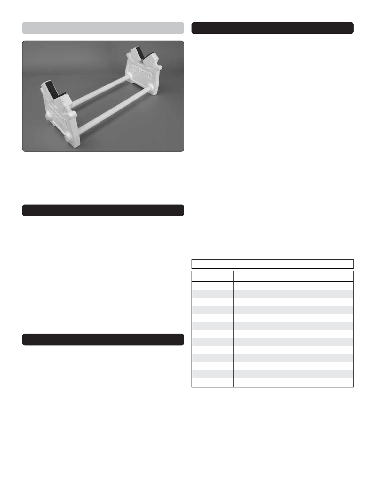
Building Stand
ORDERING REPLAC EMENT PARTS
Replacement parts for the Great Planes Sport Scale P-51 ARF
are available using the order numbers in the Replacement
Parts List that follows. The fastest, most economical service
can be provided by your hobby dealer or mail-order company.
To locate a hobby dealer, visit the Hobbico web site at www.
hobbico.com. Choose “Where to Buy” at the bottom of the menu
on the left side of the page. Follow the instructions provided
on the page to locate a U.S., Canadian or International dealer.
Parts may also be ordered directly from Hobby Services by
calling (217) 398-0007, or via facsimile at (217) 398-7721, but
full retail prices and shipping and handling charges will apply.
Illinois and Nevada residents will also be charged sales tax. If
ordering via fax, include a Visa® or MasterCard® number and
expiration date for payment.
A building stand or cradle comes in handy during the build. We
use the Robart Super Stand II (ROBP1402) for all our projects
in R&D, and it can be seen in pictures throughout this manual.
IMPORTANT BUILD ING NOTES
● Photos and sketches are placed before the step they refer
to. Frequently you can study photos in following steps to
get another view of the same parts.
● The stabilizer and wing incidences and engine thrust angles
have been factory-built into this model. However, some
technically-minded modelers may wish to check these
measurements anyway. To view this information visit the web
site at www.greatplanes.com and click on “Technical Data.”
Due to manufacturing tolerances which will have little or no
effect on the way your model will fl y, please expect slight
deviations between your model and the published values.
KIT IN SPE CTIO N
Before starting to build, take an inventory of this kit to make
sure it is complete, and inspect the parts to make sure they
are of acceptable quality. If any parts are missing or are not
of acceptable quality, or if you need assistance with assembly,
contact Pr oduct Support. When reporting defective or missing
parts, use the part names exactly as they are written in the
Kit Contents list.
Mail parts orders and payments by personal check to:
Hobby Services
3002 N Apollo Drive, Suite 1
Champaign IL 61822
Be certain to specify the order number exactly as listed in the
Replacement Parts List. Payment by credit card or personal
check only; no C.O.D.
If additional assistance is required for any reason contact
Product Support by e-mail at productsupport@greatplanes.
com, or by telephone at (217) 398-8970.
REPLACEMENT PARTS LIST
Order No. Description
GPMA4080
GPMA4081
GPMA4082
GPMA4083
GPMA4084
GPMA4085
GPMA4086
GPMA4087
GPMA4088
GPMA4089
GPMA4090
GPMA4091
GPMA4092
Fuselage
Wing
Vertical Stabilizer
Horizontal Stabilizer
Cowl
Hatch with Canopy
Canopy
Wing Tube
Landing Gear
Gear Doors
Spinner
Wing Scoop
Decals
Great Planes Product Support
3002 N Apollo Drive, Suite 1 Ph (217) 398-8970, ext. 5
Champaign, IL 61822 Fx (217) 398-7721
E-mail: airsupport@greatplanes.com
5
Cut Off
Unused Arms
5/64" [2mm]
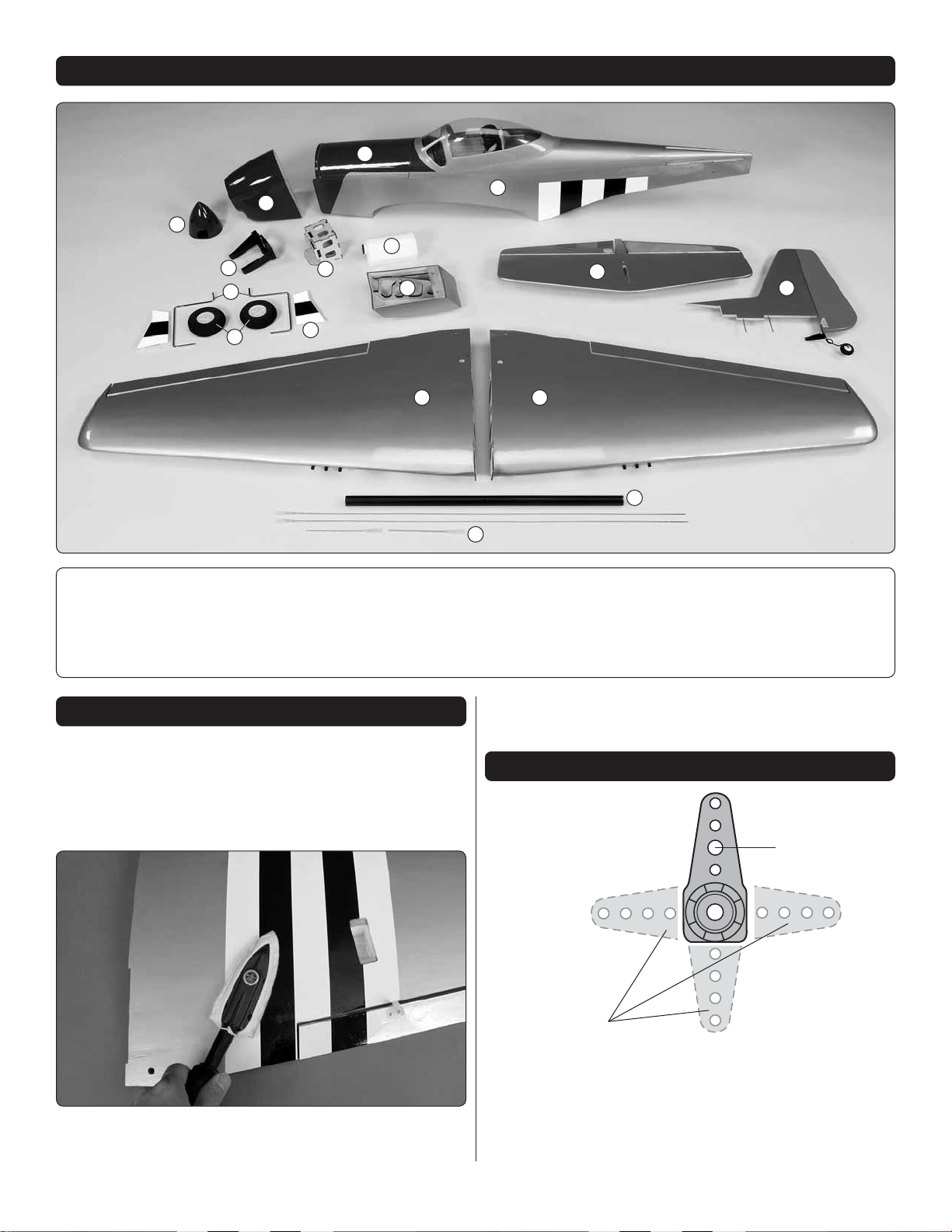
KIT CONTENTS
6
12
11
14
15
1. Left Wing Panel
2. Right Wing Panel
3. Horizontal Stabilizer
4. Vertical Fin
5. Fuselage
8
9
10
7
13
6. Hatch
7. Air Scoop
8. Cowl
9. Fuel Tank
10. Brushless Motor Mount
5
3
4
2
17
1
11. Engine Mount
12. Spinner
16
16. Wing Joiner Tube
17. Pushrods
13. Landing Gear Doors
14. Landing Gear Wires
15. Main Wheels
1. If you have not done so already, remove the major
❏
parts of the kit from the box and inspect for damage. If any
parts are damaged or missing, contact Product Support at
the address or telephone number listed in the “Kit Inspection”
section on page 5.
2. Remove the tape and separate all the control surfaces.
❏
Use a covering iron with a covering sock on high heat to tighten
PREPARATION S
the covering if necessary. Apply pressure over sheeted areas
to thoroughly bond the covering to the wood.
ASSEMBLE THE WI NGS
1. Test fi t a four-armed servo arm onto each aileron servo
❏
and determine the best orientation of the arms that will position
them closest to perpendicular to the servo cases. Look at the
photo in step 2 and cut off three of the four arms of each servo
arm to match the photo. Enlarge the second inner hole of
each remaining arm with a 5/64" [2mm] drill bit.
6
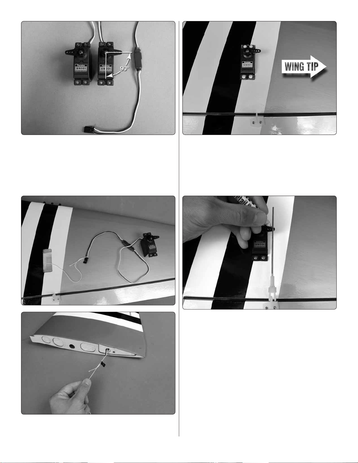
2. Attach a 6" [152mm] servo extension to each aileron servo
❏
and secure the connector using tape or heat shrink tubing
(not included). Center the servos with your radio system and
install the servo arms to the servos perpendicular to the servo
cases as shown. Be sure to reinstall the servo arm screws
into the servos. Install the rubber grommets and eyelets onto
the servo mounting tabs.
4. Fit the servos into the servo openings and drill 1/16"
❏
[1.6mm] holes through the mounting tabs on the servo cases
into the rails. Thread a servo mounting screw (included with
the servo) into each hole and back it out. Apply a drop of thin
CA to each hole to harden the surrounding wood. When the
CA has dried, install the servos into the openings using the
screws supplied with the servos.
3. Use the strings taped inside the aileron servo openings
❏
to pull the servo leads through the wing.
5. Locate the two 4" [102mm] pushrods that have clevises
❏
already threaded onto the ends of the wires. Slide a silicone
clevis retainer onto the base of each clevis. Attach the clevises
to the outer holes of the aileron control horns. With the ailerons
in the neutral positions (use tape or a small clamp to hold
them in place), mark the pushrod wires where they cross the
second inner holes in the servo arms.
7
Servo Horn
1/16"
2-56 (.074")
Pushrod Wire
FasLink
6. Make a 90 degree bend at the mark on each pushrod
❏
and cut off the excess pushrod 1/4" [6mm] beyond the bends.
Attach the pushrods to the servo arms using nylon FasLinks.
Thread the clevises up or down on the pushrods as necessary
to center the ailerons with the servo arms still perpendicular
to the servo cases. When satisfi ed, slide the silicone clevis
retainers to the ends of the clevises to secure them.
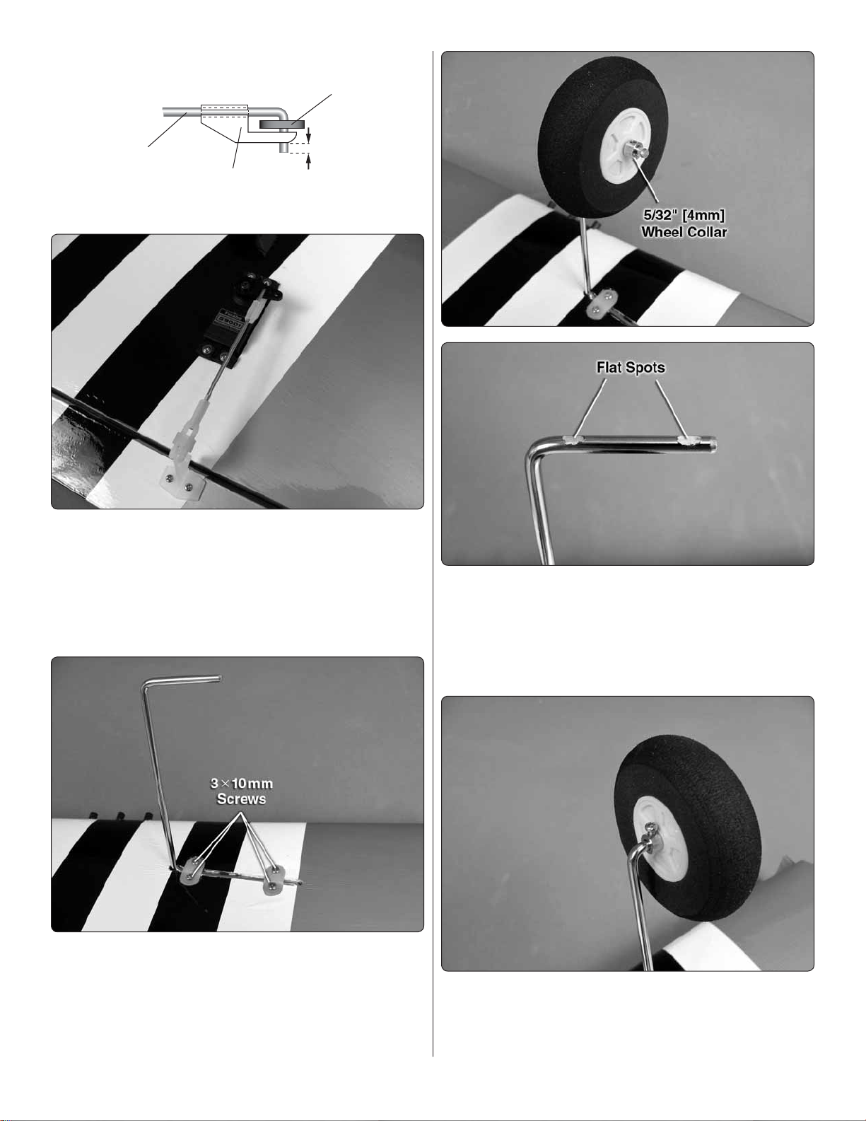
8. Slide a 5/32" [4mm] wheel collar onto each axle followed
❏
by a main wheel and another 5/32" [4mm] wheel collar. With
the collars and wheels centered on the axles, use a felt-tip
pen to mark the hole location of each collar onto the axles.
Remove the collars and wheels and use a fi le or rotary tool
to grind fl at spots onto the axles at your marks.
7. Thread a 3x10mm self-tapping screw into each landing
❏
gear strap hole and back it out. Apply a drop of thin CA
glue to each hole and allow the glue to dry completely. Fit
the main landing gear legs into the slots in the wings and
secure them using nylon landing gear straps and 3x10mm
self-tapping screws.
9. Reinstall the wheel collars and wheels onto the axles.
❏
Tighten a 3x5mm machine screw with thread locking compound
into each wheel collar. Be sure that the wheels rotate freely. A
couple drops of oil onto each axle is recommended.
8
 Loading...